Seismic design of steel halls
Is a single dominant vibration mode sufficient, or should multiple vibration modes be considered in seismic analysis?
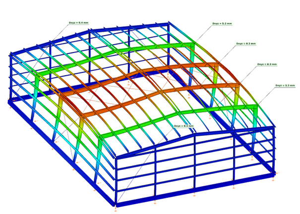
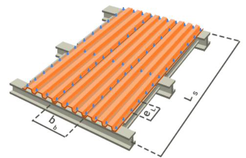
Steel portal frames are frequently used in industrial and logistics buildings as primary load-bearing structures. Their seismic behavior is strongly influenced by the stiffness of the roof diaphragm and by the interaction between the main portal frames and secondary structural subsystems such as endwalls.
In seismic design, engineers often assume that the global response of such buildings can be represented by a single dominant vibration mode. This assumption is valid when the roof diaphragm is sufficiently rigid and the first transverse mode mobilizes most of the structural mass. However, when the diaphragm is flexible or when different structural parts participate in different vibration modes, higher modes may also contribute to the seismic response.
This article investigates how the choice between a single-mode and a multi-modal approach affects the seismic design of steel halls modeled in Consteel. Through a comparative example, the study demonstrates the implications of different modal combination techniques and discusses how reliable internal forces can be obtained while maintaining compatibility with stability verification procedures according to EN 1993-1-1.
Case with a Rigid Roof Diaphragm
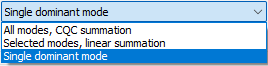
Single dominant mode
If a building is designed with a sufficiently rigid roof diaphragm, a single transverse vibration mode is typically able to mobilize close to 90% of the total participating mass. In such cases, the Single dominant mode method is an efficient and preferred design method.
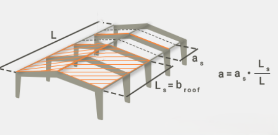
A rigid roof diaphragm can be achieved by:
- Using an adequate trapezoidal steel deck, modeled in Consteel either
- as a Shear Field with a high shear stiffness parameter (“S” value), or
- by introducing equivalent dummy roof bracing diagonals with rod diameters calibrated to reproduce the diaphragm shear stiffness.
- Alternatively, real bracing elements may be added along the sidewall columns or from the eaves to the ridge along the building length.
Case without a Rigid Roof Diaphragm
If a rigid diaphragm is intentionally not assumed, a single vibration mode will generally not represent the full seismic response in the transverse direction.
Single dominant mode
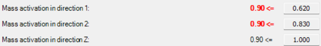
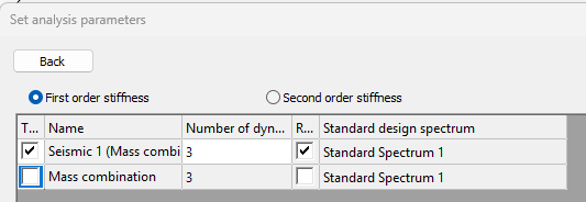
A dynamic eigenvalue analysis is first performed to determine the natural vibration modes of the structure. In Consteel, this analysis calculates the eigenfrequencies and corresponding mode shapes based on the structural stiffness and mass distribution, considering both the elastic stiffness and second-order geometric stiffness of the structure. The first three vibration modes are then evaluated for their mass participation in the transverse direction.
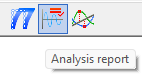
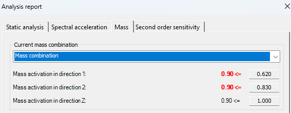
After the calculation, the mass participation for each principal direction (X, Y, and Z) can be viewed in the Analysis tab under the Analysis report, in the Mass section. In the examined case:

Log in to view this content
Online service access and support options are based on subscription plans. Log in to view this content or contact our sales department to upgrade your subscription. If you haven’t tried Consteel yet, try for free and get Pro access to our learning materials for 30 days!