- Contents
Dataprocessing and velocity-based validation on a simple block
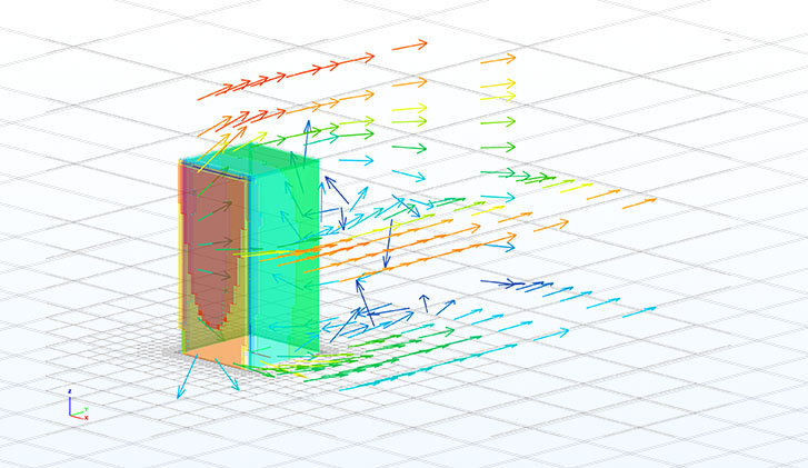
In this second article of our wind simulation series, we will delve into two critical topics of wind simulation for structural engineering. The first one is data processing, a collective name for the most relevant steps of the fluid-dynamics aided wind load generation, such as mesh creation, executing the simulation itself and extracting initial results. While the second one is a preliminary velocity-based validation example to broadly explain the influence of the simulation parameters, to ensure that the results are accurate and useful for practical design applications.
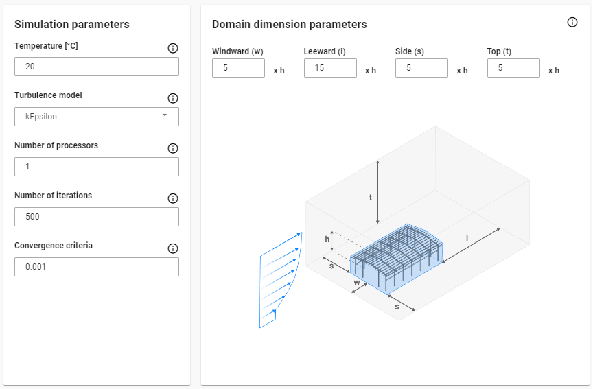
In the previous article [1], we covered the preprocessing steps for wind simulation, including setting up the geometry using simulation surfaces and boundary conditions (wind effects and directions). These parameters were mostly aligned with the underlying logic of the standards, therefore their interpretation is relatively straightforward. However, to carry on it is inevitable to briefly introduce the simulation related parameters too, which are divided into two categories.
The basic settings are the 'mesh size on structure' and the 'mesh refinement factor'. The first one is the average edge size on the structure for both of the generated meshes, the finite element mesh for mechanical and the the finite volume mesh for fluid-dynamical purposes, presented in the previous article. While the refinement factor is used to increase the finite volume cell edge sizes at the boundaries of the simulation domain, which are considered to be far enough from the building, therefore it is not necessary to calculate field values as densely as it is calculated around the building according to the ‘mesh size on structure’ parameter, leading to quicker simulations.
Note: Larger mesh size on the structure and larger refinement factor values are leading to coarser mesh, therefore a quicker simulation but less accurate results!
The advanced settings are a set of parameters to control the simulation in the background, with default values usually leading to adequate results. However the goal of this article is to provide an insight in their influence.
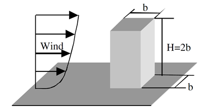
To ensure a meaningful validation, a wind tunnel test was replicated, utilizing experimental data and computational parameters from the Architectural Institute of Japan (AIJ) Benchmarks [2] . The experiment was carried out in a small circulatory wind tunnel at the Technical Research Institute of Shimizu Corporation. The test model consisted of an acrylic cuboid with dimensions of 160 mm in height and 80 mm in width. The inflow wind velocity was set at 6.75 m/s, with a measured turbulence intensity of approximately 0.5%.
Note: These validations were performed in a development version of our tool in the Grasshopper enviroment. In Consteel the tool focuses on the generation of wind loads, therefore can be utilized to extract pressure values.
Several key aspects were considered throughout the entire analysis process of the case study. Given that the model represents one of the simplest geometries encountered in practice, and that its structural behavior is straightforward to interpret within the context of standard guidelines, this case served multiple purposes. Primarily, it was used to underline the importance of conducting mesh independency tests prior to the actual simulation. As indicated in the table below, even for a simple geometry, the influence of mesh density proved to be significant — not only in terms of result accuracy but also from a performance perspective. For further investigations the “2000-4” mesh configurations was chosen, where the convergence of results became apparent.
| Mesh size on structure [m] | 8000 | 4000 | 2000 | 1000 |
| Mesh refinement factor | 2 | 3 | 4 | 5 |
| Meshing runtime [s] | 18.3 | 65.3 | 61.2 | 108.9 |
| Cell number [-] | 136432 | 150881 | 264786 | 495694 |
| Simulation runtime [s] | 65.3 | 57.9 | 151.1 | 343.4 |
| Iterations [-] | 264 | 182 | 260 | 314 |
| Fx+ [kN] | 197 | 203.0 | 205.6 | 203.5 |
| Fy+ [kN] | 94.4 | 94.5 | 89.9 | 89.7 |
| Fy- [kN] | 94.5 | 94.4 | 89.8 | 89.8 |
| Fz+ [kN] | 53.6 | 52.4 | 47.7 | 48.2 |
The next aspect was to emphasize the significance of mesh refinement, particularly along the edges. For example, finer mesh resolutions capture higher suction values on the side walls, though over smaller localized areas. Consequently, it is crucial to closely monitor the global reactions from the acting pressures influenced by a given mesh configuration, as presented in the table above.
Following the initial calibration tests, five different turbulence models (k - ε, k - ω, k - ω SST, RNG k - ε, Realizable k - ε) were compared based on their respective velocity fields.
These cases were executed simultaneously to assess the impact of full processor utilization. During the meshing process, the same mesh was applied in nearly all cases; however, the runtime increased to approximately 250 seconds, which is four times longer than when the cases were run separately. This clearly indicates that the previously reported runtimes were significantly influenced by the concurrent execution of parallel processes.
Note: It is also possible to run a single simulation case in parallel, which involves decomposing the computational domain and subsequently reconstructing it. However, this decomposition process also requires computational resources, meaning that running simulations in parallel does not always result in faster execution times.
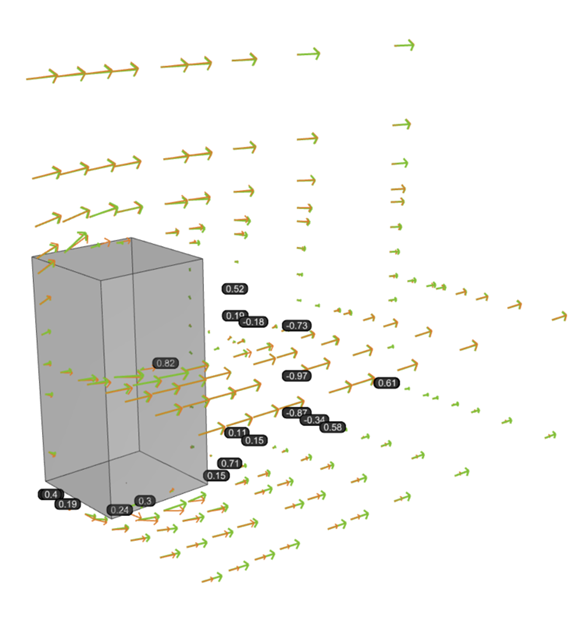
The primary metric used for each case was the average directional deviance of the velocity vectors obtained by simulation from the benchmark experiment velocity vector, where 0 indicates parallel vectors and 1 indicates perpendicular vectors. Across all scenarios, similar behavior was observed in the wake region of the building, underlining a key limitation of RANS-type turbulence models. Specifically, these models tend to capture only a single dominant vortex during flow separation, resulting in the highest deviations behind the building, as well as near the ground.
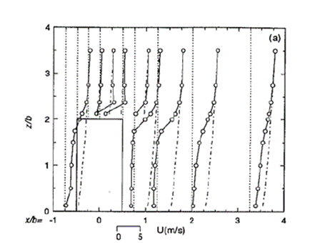
To assure relevant and transparent validations the original AIJ benchmark results were compared with the results obtained using several turburent models in a similar manner. A set of points close to the building inside of the calculation domain were monitorized.
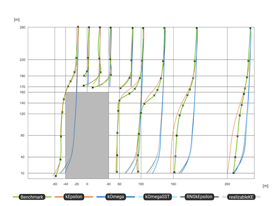
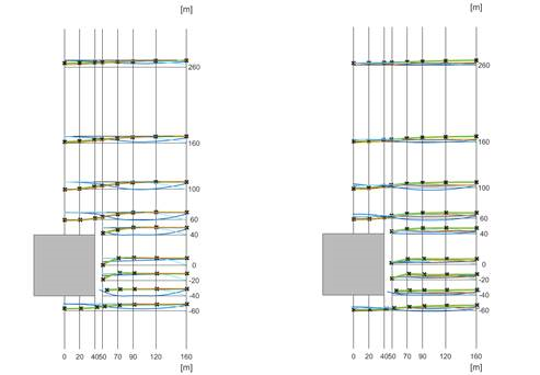
In conclusion, while these validations based on velocity fields may have limited direct relevance from a structural engineering perspective, understanding the flow behavior around buildings and calibrating simulations appropriately remains crucial. It is evident that even for simple geometries, simulation results are highly sensitive to parameter variations, underlining the need for an iterative approach to ensure mesh independence and result convergence.
During the investigation, the objective was to establish a general guideline for better starting values. As such, a mesh size on structure between e/12 and e/20 is recommended for the structure, where "e" corresponds to the minimum value between the crosswind width of the structure and twice its height, as defined in EC 1991-1-4 [3]. Using this as a starting point, it is advisable to apply an iterative simulation process with a refinement factor ranging from 5 to 0, while continuously monitoring the convergence of pressure results. This iterative method forms the foundation of the load generation procedure during the post-processing phase, which will be further discussed in upcoming knowledge base materials.
References:
[1] Preprocessing wind simulation for structural engineering purposes
[2] Guidebook for CFD Predictions of Urban Wind Environment - Architectural Institute of Japan
[3] EN 1991-1-4: Eurocode 1: Actions on structures - Part 1-4: General actions - Wind actions

