How load combination filter works for 'Steel - Dominant results' and corresponding 'Limitation' options?
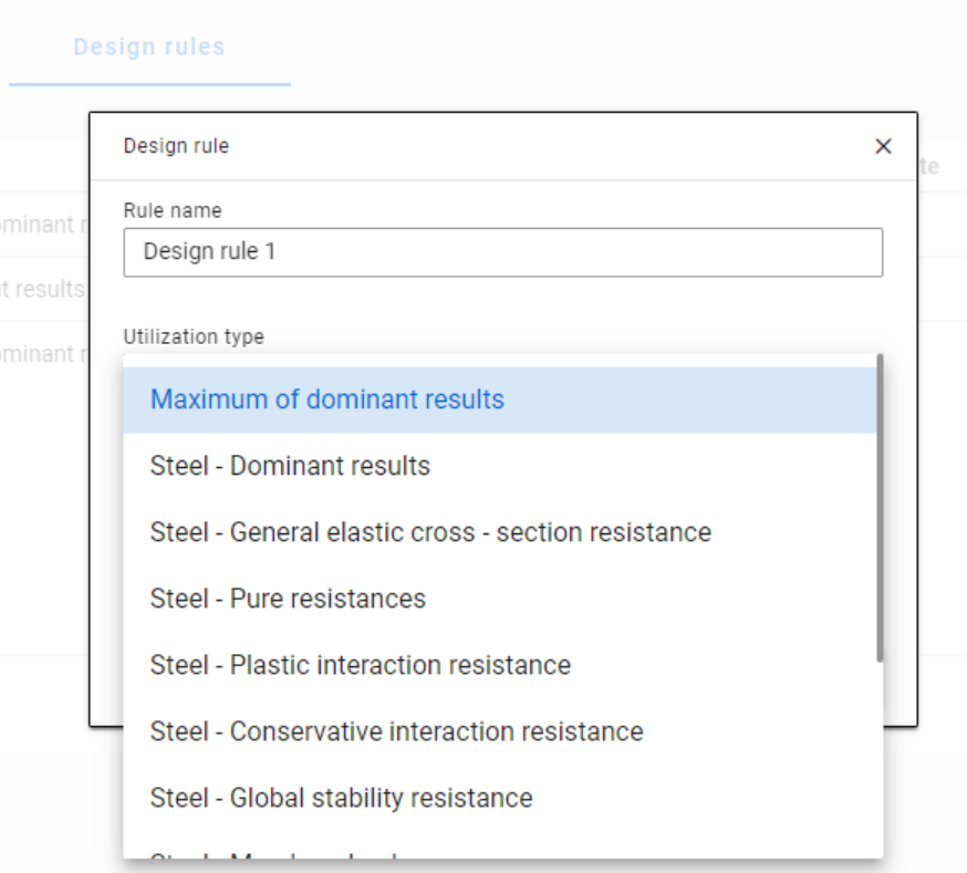
When applying design rules in load combination filter, the most frequently used utilization type is Steel - Dominant results. What results are exactly considered by this option and what do corresponding limitations mean?
Introduction
There are four ways to apply load combination filter: based on limit states and load cases, manually, and by rules. Unlike the other three methods, filter by rules is only possible based on analysis and/or design results.
The most effective way to reduce the number of load combinations is definitely the use of design rules.
With design rules, load combinations can be selected based on utility ratios. Utilizations are available from several design checks, including dominant results and detailed verifications for steel elements, such as general elastic cross-section check, pure resistances, interactions, and global stability.

The meaning of the dominant check
The dominant check is not always the check which gives the maximal ratio but the one with the maximum RELEVANT ratio. Typical example: if plastic interaction formulas are valid, those results will be dominant over general elastic cross-section check results, although the latter are higher.
Steel - Dominant results
Steel – Dominant results option contains the utility ratio of the dominant check at every finite element node, in all load combinations. Meaning that there are as many utilization values as the number of load combinations calculated, in every FE node.
It is also important to understand the difference between the utilizations of Maximum of dominant results and Steel -Dominant results. Maximum of dominant results option contains the dominant utility ratio of the dominant load combination at every node, like an envelope of Steel-Dominant results. Meaning there is only one utilization value in every FE node. Also, it is the same as the dominant result table on Global checks tab.
When a rule is applied, the utilizations of the chosen utilization type are compared against the limitation. The load combinations which give the results that correspond to the limitation, are selected by the rule. Every FE node of the selected model portion is examined.
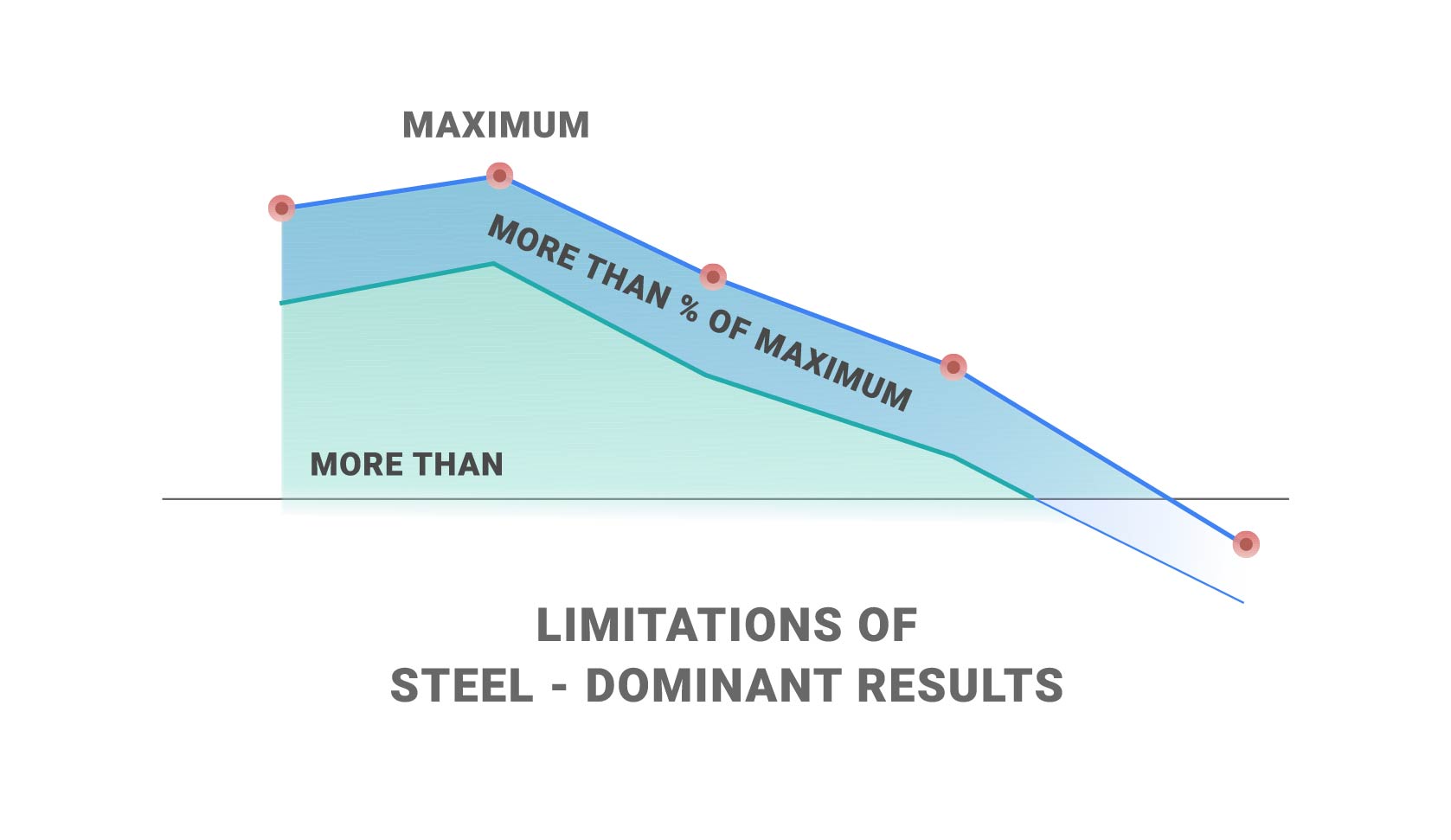
Limitations in case of Steel – Dominant results
- Maximum: to select the combinations which cause the maximum utilization at any node. It can be the same as Maximum of dominant results, except if there are combinations where the utilization is the same and it is maximal. In this case, here all the combinations are selected, while with Maximum of dominant results, there is always one maximum.
- More than % of maximum: to select the combinations as in ’Maximum’ plus those which cause utilization that is more than the given percentage of the maximum. E.g. at a certain point max utility ratio is 80%, Limitation= More than 90% of maximum. This rule will select all the load combinations which cause utility ratios between 0,9*80=72% and 80%.
- More than: to select the combinations which cause utilization more than the defined value at any point.
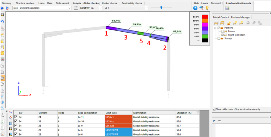
Let’s see an example of a simple 2D frame for better explanation. Right-side beam is in the portion for which three design rules were applied. Five points are selected for representation but of course all the nodes of the portion are examined against the rules’ limitations.

The utilizations of the five dedicated FE node in all 11 load combinations are shown on the below diagram. (To find all of these utilizations in the attached model, global checks must be calculated for the load combinations one-by-one.)
Log in to view this content
Online service access and support options are based on subscription plans. Log in to view this content or contact our sales department to upgrade your subscription. If you haven’t tried Consteel yet, try for free and get Pro access to our learning materials for 30 days!

