- Conţinut
Preprocessing wind simulation for structural engineering purposes
As we prepare to publish the first version of our wind simulation tool, let's explore the theoretical and technological background that makes it unique. Throughout the development process, we identified a significant gap between computational fluid dynamics and structural mechanics, highlighting a substantial amount of knowledge that needs to be bridged. With our commitment to fostering a responsible developer-user community, we've decided to release several knowledge base materials in the upcoming months to explain the key features that primarily will operate behind the scenes within the Consteel design workflow. The first step is to understand the prerequisites of the tool and how we aim to align the finite element, standard-based approach of structural engineering with the finite volume methods used in computational fluid dynamics. In short, we refer to this as preprocessing. So, let's delve into what that entails.
In structural engineering, the evaluation of wind-induced loads is typically carried out using standard procedures designed to simplify the process in various ways. However, when more advanced methodologies like computational fluid dynamics are utilized, these standards inevitably serve as a benchmark, providing a basis for comparison against the pressure results generated by the simulation.
The entire development process was centered around determining wind profiles using standard procedures. The first implementation follows Eurocode 1-4, which is based on a set of parameters, organized similarly to the Consteel interface for defining meteorological effects.
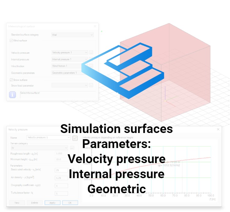
The velocity pressure parameters include the basic wind velocity (vb), which can be selected based on geographical zones specific to each country, and the terrain category. The terrain category, as defined in a selected national annex, provides values for roughness length (z0), minimum height (zmin), and the terrain factor (kr). The terrain factor can either be a fixed value, as specified in several national annexes, or calculated using a proposed formula based on the roughness length and minimum height. Additionally, the selected national annex provides essential values for air density (ρ), orography coefficient (co(z)), and turbulence factor (kI), among others.
Internal pressure parameters include coefficients that modify the velocity pressures for a given wind direction, replicating the effects of internal pressures as described in the Eurocode.
Note: At this stage of development, we strongly recommend using the tool solely for achieving external pressure on closed, 'air-tight' buildings.
The geometric parameters include the basic wind direction definition according to the global coordinate system (θ = 0°), the ground level (Z), and other dimensional parameters. These parameters can be used to create zoned loads, allowing for load contours similar to those defined in the Eurocode.
Finally, simulation surfaces are the surfaces enclosing the investigated building. acting as load transfer surfaces for subsequent mechanical calculations.
Note: Currently, simulations are limited to surfaces and cannot be performed on beam members.
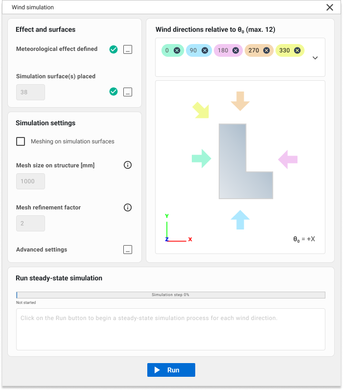
Once all the necessary parameters which are aligned with the underlying logic of the standards are collected, the actual preprocessing can be initiated from a separate dialog. This interface requires additional CFD-related inputs, which will be explained in the upcoming knowledge base materials.
The preprocessor can be observed as an operational phase or a collection of methods, with two primary tasks executed based on the previously gathered parameters. The first task is to convert the input geometry into a specially developed mesh format (FoamMesh). This format resembles a traditional finite element mesh, featuring triangular or quadrilateral planar faces and vertices, and is capable of storing simulation results. Additionally, FoamMesh can interpret meshes with polygonal faces ('Ngons'), typically generated by OPENFOAM®, which can often be non-planar. Besides, faces can also form zones based on their results. For representation purposes, these meshes can be viewed as a list of polylines (or two-dimensional figures in Consteel) at any time.
Note: The finite element mesh used for simulation differs from the mesh employed for load distribution in mechanical calculations. The internal vertices of this simulation-specific are obtained through the iterative offset of the surface contour, aiming to primarily create quadrilateral faces. These quad faces are preferred for zoned load creation during the postprocessing phase.
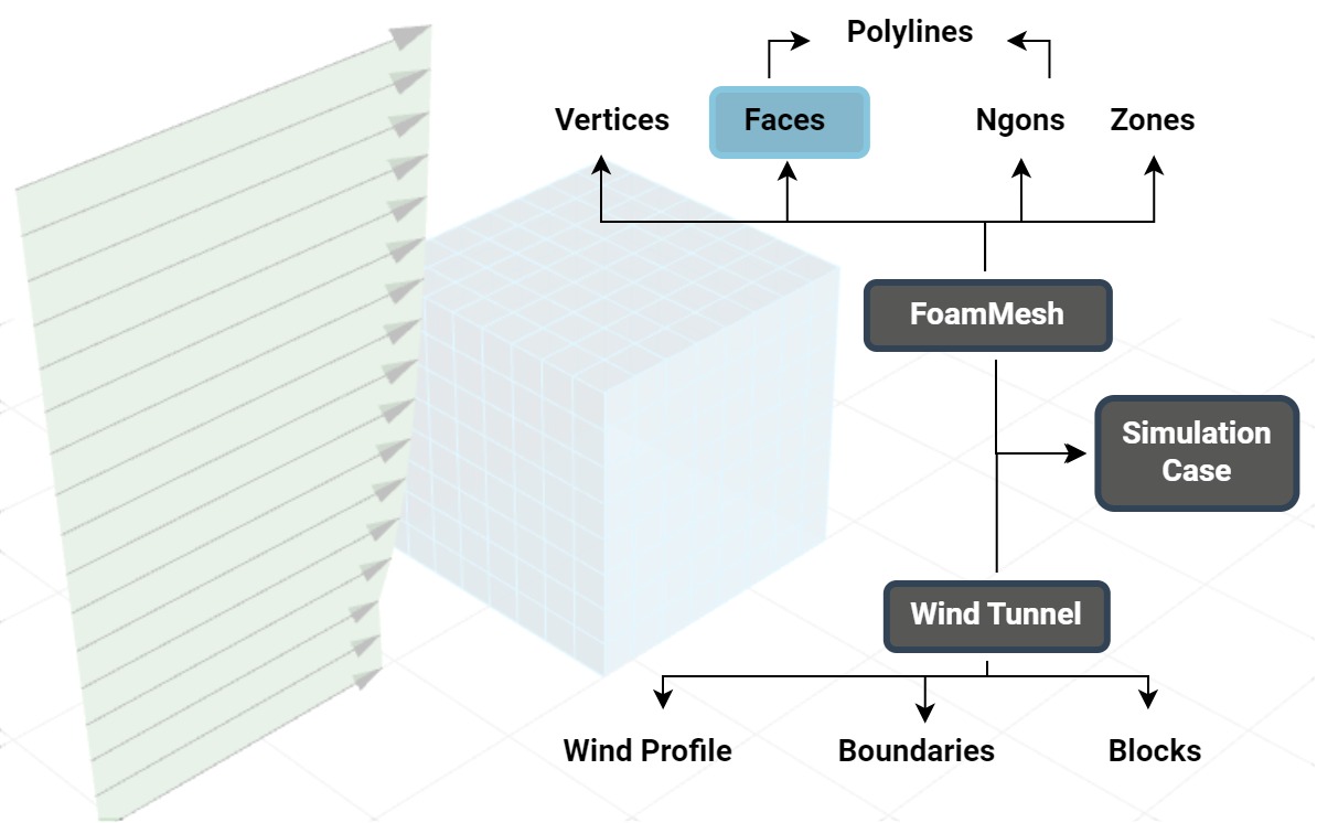
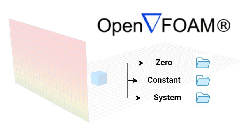
The other task is to generate a virtual wind tunnel, which consist of the wind profile according to the parameters, and the actual closed domain in which the simulation is performed defined by boundaries and inner blocks (finite volumes). Having these two it is possible to create the simulation case contents proper to the OPENFOAM® hierarchy. The wind flow parameters are stored in 'zero' folder, mesh generation both in 'constant' and 'system', while solution and result query parameters in 'system'.
Note: For each wind direction a separate simulation case is performed, with it’s own independent finite volume mesh based wind tunnel. However, the finite element mesh of the building is identical, regardless the direction.
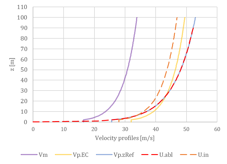
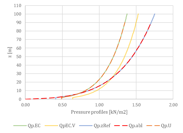
Regarding the wind profile, the clear objective is to introduce a wind velocity profile that replicates the peak pressure profile specified by the code. However, defining this profile is not straightforward. The figures below illustrates various approaches, with the QpEC function representing the general 'target' profile according to Eurocode.
Since Eurocode typically neglects the second-order term of turbulence intensity (considering only 1 + 7Iv(z)) when calculating QpEC, a significant difference arises if we calculate the velocity pressure, QpEC.V, from the peak velocity profile (using 1 + 3.5Iv(z) for turbulence intensity). As a result, VpEC is not intended to be directly implemented in OPENFOAM®.
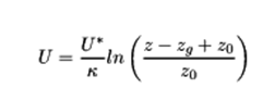
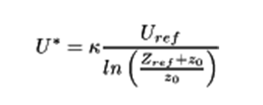
Besides the standards, OPENFOAM® offers a default approach for logarithmic atmospheric boundary layers (Uabl), based on the friction velocity U* calculated at a reference height. However, the resulting Qp.abl also shows a significant difference, lacking the constant segment below the minimum height (zmin). Otherwise, this profile is similar to a standard Vp(zRef), which is evaluated along the height using only one exact turbulence intensity value calculated at the reference height (Iv(zref)).
The logarithmic profile evaluated by the atmospheric boundary layer approach of the OPENFOAM® is according to the followings:
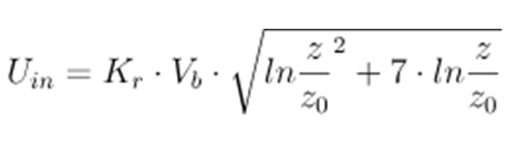
Therefore, it was necessary to develop a unique solution within OPENFOAM® for the determination of the Uin as the inlet peak velocity profile, which produces the desired QpEC. This uses the following formula:
For an inlet wind profile using the k-ε turbulence model the initialization of the k and ε field values is also necessary. For this, there are also different approaches to consider. The basic atmospheric boundary layer of OPENFOAM® calculates a constant value along the height automatically, according to:

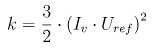
However, the inlet turbulent kinetic energy is generally calculated based on the inlet reference velocity and the turbulence intensity, which is defined by Eurocode according to the terrain parameters as presented previously:
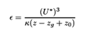
Similarly for the inlet ε there is a default automatic way used by the OpenFOAM based on the friction velocity:
And there is also an approach considering the turbulent length intensity which can be evaluated according to a Eurocode procedure:
These approaches were compared for both the mean velocity and the peak velocity profiles, as shown in the figure below. The peak pressures correspond to the values measured on the windward wall of a simple 8 m x 8 m x 8 m cuboid. The naming conventions for the profiles are as follows: inlet velocity profile (mean and peak) – inlet turbulent kinetic energy (automatic - a or calculated - c) – inlet turbulent dissipation rate (automatic - a or calculated - c).
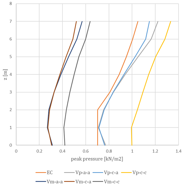
In conclusion, the profile chosen for implementation is the Uin, with automatic evaluation applied to both the inlet turbulent kinetic energy (k) and the inlet turbulent dissipation rate (ε). The effects of various turbulence models, along with the influence of different meshing procedures on the geometry, to which we refer as dataprocessing, will be discussed in upcoming knowledge base materials. So stay tuned as we explore different validations of this newly developed tool.
Autorul
 Ádám Kis
As a Structural Engineer he was obsessed with parametric design methods. He is convinced that it can be efficient for any design task. This is how he came to the dark side and works as a developer on Pangolin. As a PhD student, he researches the implementation of simulation methods in Consteel.