Difference between Consteel functions "Global stability check" and "Member check"
Introduction
There are different ways to evaluate the stability of a structure. It is important to know the differences between those methods and the limits of applicability but it is also important to recognize the equalities in pure cases.
Methods of stability design
In Eurocode 1993-1-1, and so in Consteel, there are 3 methods to verify the stability of a model:
- Imperfection approach (described in Section 5.2 and 5.3)
The structural model is subjected to appropriate geometrical imperfections and after completing a second order analysis, only the cross section resistances need to be checked
- Isolated member approach ( described in section 6.3.1, 6.3.2 and 6.3.3)
The method is based on two essential simplifications:
- Structural member isolation: The relevant member is isolated from the global structural model by applying special boundary conditions (supports, restraints or loads) at the connection points which are taken into account in the calculation of the buckling resistance
- Buckling mode separation: The buckling of the member is calculated separately for the pure modes: flexural buckling for pure compression and lateral-torsional buckling for pure bending. The two effects are connected by applying special interaction factors.
- General method (described in section 6.3.4)
The basic idea behind the general method is that it no longer isolates members and separates the pure buckling modes, but considers the complex system of forces in the member and evaluates the appropriate compound buckling modes. The method offers the possibility to provide solutions where the isolated member approach is not entirely appropriate:
-The general method is applicable not only for single, isolated members, but also for sub frames or complete structural models where the governing buckling mode involves the complete frame.
-The general method can examine irregular structural members such as tapered members, haunched members, and built up members.
-The general method is applicable for any irregular load and support system where separation into the pure buckling modes is not possible.
Implementation of different approaches in Consteel
Isolated member approach is basically the reduction factor method and it can be performed in Member checks function in Consteel where it is possible to define the design parameters (e.g. effective length) by hand.
In Global checksfunction, cross-section and global buckling checks can be executed automatically according to the General method which does not require the direct introduction of effective lengths and other parameters depending on the distribution and combination of stresses along the member.
However, in pure cases (pure compression, or pure bending), buckling length calculated from general method can be equated with isolated member approach. In the following, a "how to" example will be shown on a pure compression column:
How can I get the buckling length of a certain member?
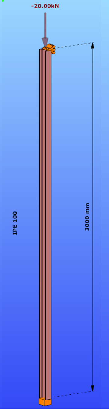
Parameters:
- Section: IPE100
- Material: S235
Main inertia around axes:
- Iy = 1708644 mm4
- Iz = 158056 mm4
Supports:
- x,y,zz on the top
- fixed on the bottom
Load: NED = 20 kN
Both the Isolated member approach and the General method require to calculate the slenderness value of the member. In case of the first method this is done through the use of buckling lengths. By using the General Method, the slenderness is calculated as the ratio of two amplifiying factors.
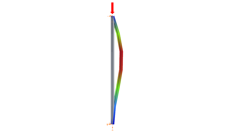
For the calculation of the equivalent buckling length we will need the first amplifier only, called critical elastic factor or alpha critical factor, obtained through a numerical analysis called linear buckling analysis.
Determination of alpha critical factor with buckling analysis:
Alpha critical factor: Minimum amplifier for the design loads to reach the elastic critical resistance of the structural component with regards to lateral buckling.

Log in to view this content
Online service access and support options are based on subscription plans. Log in to view this content or contact our sales department to upgrade your subscription. If you haven’t tried Consteel yet, try for free and get Pro access to our learning materials for 30 days!