Did you know that you can use Consteel to calculate support settlement?
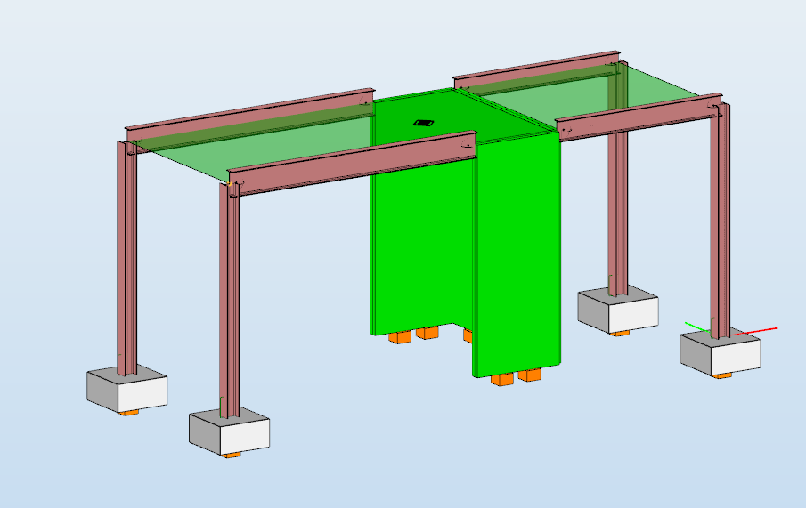
Settlement verification is an essential part of designing pad foundations, ensuring that the vertical displacement under service loads does not compromise the structural performance. Consteel allows engineers to perform these checks directly within the model, fully aligned with EN 1997-1:2004 (Eurocode 7), Section 6.6.2.
According to Eurocode 7, the procedure is based on evaluating the deformation of the supporting soil due to applied loads. This requires defining the soil profile with appropriate deformation parameters and determining the distribution of vertical stresses beneath the foundation. The calculation is performed over the depth where the load-induced stress increase remains relevant compared to the in-situ stress conditions.
The resulting deformation is obtained by considering the compressibility of the soil layers and, where necessary, the time-dependent behavior of fine-grained soils. The calculated total settlement is then assessed against allowable limits defined for the structure, ensuring that serviceability criteria related to deformation and functionality are satisfied.
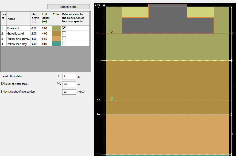
The software allows the user to define the key parameters affecting settlement:
- Soil profile: Each layer’s thickness and deformation modulus can be specified to represent compressibility and stiffness.
- Settlement limit: Allowable settlement values can be set to check serviceability.
- Drained or undrained conditions: The calculation can consider short-term or long-term soil response.
- Water table level: Groundwater depth can be defined, affecting effective stresses and settlements.
Before performing settlement verification, ensure that the necessary load combinations are included in the structural model. Consteel calculates reaction forces at the footing level for the Serviceability Limit State (SLS) combinations. These reactions are then used to evaluate settlement as part of the foundation checks.
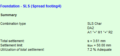
Consteel performs total settlement checks for each spread footing. The software provides:
- Total settlement value under SLS loads
- Allowable settlement limit according to design criteria
- Utilization ratio (the proportion of allowable settlement used by the calculated settlement)
This information allows engineers to verify whether the foundation satisfies serviceability requirements and determine if adjustments to footing dimensions, reinforcement, or soil treatment are necessary.
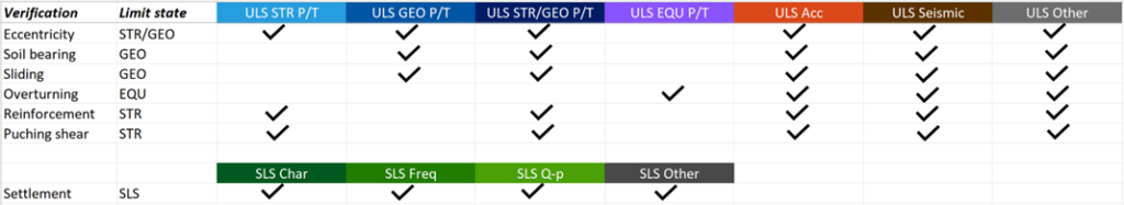
Consteel integrates settlement verification with other foundation design checks, including:
- Soil bearing verification (EN 1997-1 Annex D)
- Sliding and overturning (EN 1997-1 Sections 6.5.3, 6.5.4; EN 1990 Section 6.4.2)
- Reinforcement bending (EN 1992-1-1)
- Punching shear (EN 1992-1-1 Section 6.4.4)
Any modification to the footing geometry or structural loads automatically triggers a reanalysis, ensuring that settlements are always calculated accurately.
By integrating settlement calculations with the design workflow, Consteel allows engineers to check pad foundations for serviceability directly within the model. Total settlement, limits, and utilization ratios are clearly presented, enabling efficient verification of Eurocode 7 requirements without additional manual calculations.
Download the example model and try it!
Download modelIf you haven’t tried Consteel yet, request a trial for free!
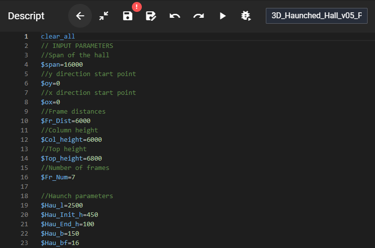
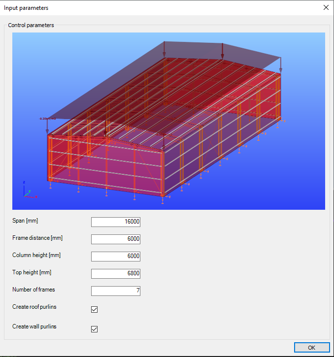
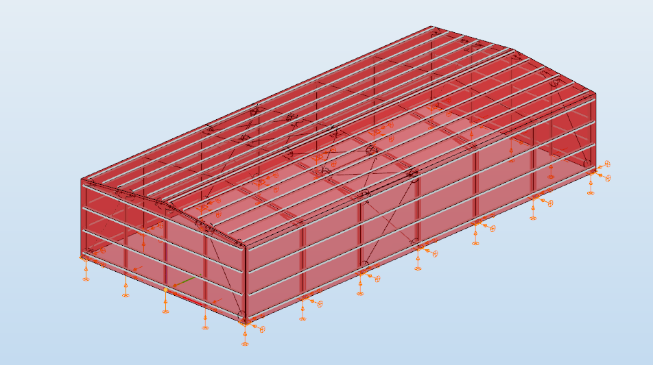
Try Consteel for freeDid you know that you can use Consteel to apply your own scripts to build models and perform calculations?
Try it!
If you haven’t tried Consteel yet, request a trial for free!
Try Consteel for free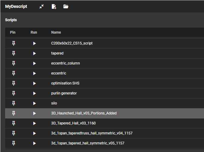
Did you know that you could use Consteel to build 3D models with smart link elements which automatically adapt the model when profiles are changed?
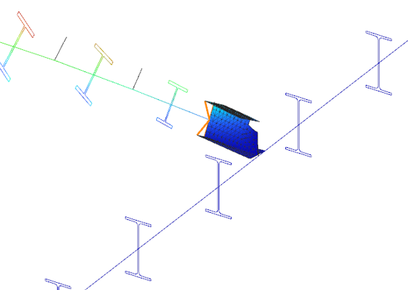
Link elements are used to connect members that are not directly joined. In Consteel, three types of link elements are available: Link, Smart Link, and Constraints.
A smart link is a dynamic connection element designed to simplify the management of geometric changes between connected members. It automatically follows the movement, rotation, or profile changes of the primary member it is attached to, while also ensuring that any connected secondary member adapts accordingly.
A common application is connecting a main beam to a purlin or other secondary elements, with smart links positioned at specific points. They enable easy attachment of additional members while preserving the defined eccentricity, and automatically adapt to any changes in the main beam’s geometry or profile.
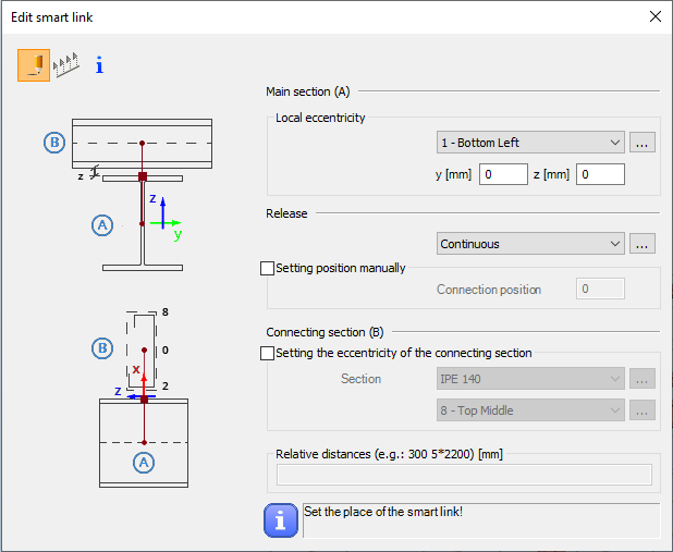
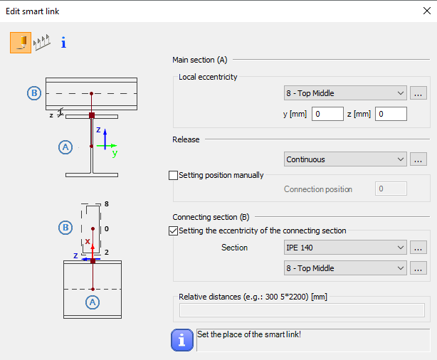
The Smart Link function, located on the Structural Members tab, opens the Edit Smart Link dialog box after activating the command. This allows you to:
- define the eccentricity of the link relative to the main section
- set the connection type in the Release field
The connection position can be specified manually or left to default automatically to the edge of the main member.
Defining the connecting section is optional. When specified, an eccentricity can be assigned, and the program automatically determines the link length based on the section height and reference point.
Smart links can be placed individually by clicking on a member or in groups by specifying distances from the member’s start. Any placement conflicts are indicated by a warning.
By combining associative behavior with precise control, Smart Links support efficient and reliable 3D modeling in Consteel. They help maintain structural intent throughout design changes, reduce manual corrections, and improve overall model consistency.
For workflows where geometry evolves and secondary members must remain accurately connected, Smart Links provide a clear advantage and enable a more resilient and adaptable modeling process.
Download the example model and try it!
Download modelIf you haven’t tried Consteel yet, request a trial for free!
Try Consteel for freeDid you know that you could use Consteel to calculate rotational stiffness for bolted column/beam moment bearing connections?
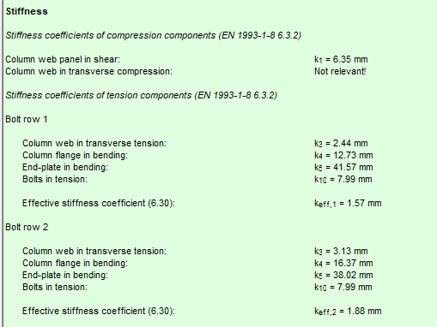
This capability is implemented through the Joint module, where connection behavior is evaluated in accordance with Eurocode EN 1993-1-8. The software does not treat joints as idealized (purely pinned or rigid), but allows the engineer to consider semi-rigid behavior by calculating the actual rotational stiffness based on connection components such as bolts, end plates, welds, and stiffeners.
In practical terms, the rotational stiffness is derived from the component method, where the stiffness contribution of each tension and compression component is taken into account. This enables a more realistic representation of the joint response, especially for moment-resisting beam-to-column connections where stiffness significantly influences global structural behavior.
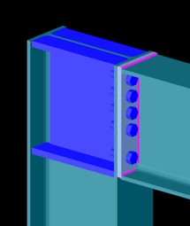
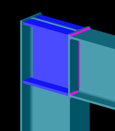
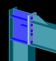
Bolted connection
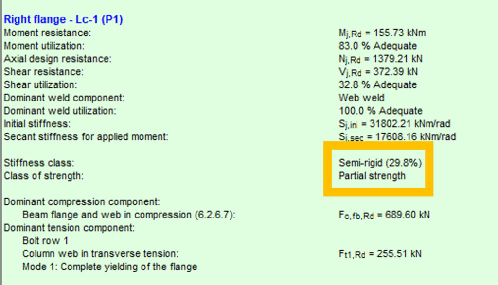
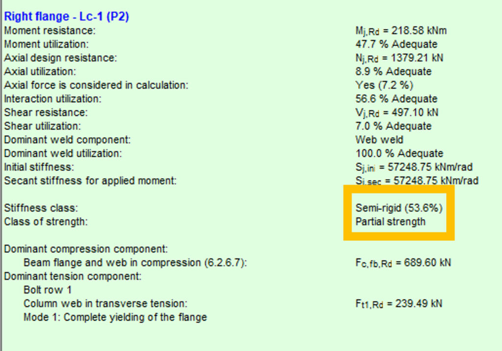
In this case, the connection exhibits relatively low rotational stiffness compared to a fully rigid joint. The flexibility is primarily governed by bolt deformation and end plate bending. Such connections are typically classified as semi-rigid and partial strength. They allow noticeable rotation under moment, which can be beneficial for redistribution of internal forces but must be considered in global analysis.
Bolted connection
This configuration shows a higher stiffness due to improved component arrangement, such as thicker end plates, larger bolt diameters, or additional stiffening. Although still semi-rigid, the connection provides significantly more resistance to rotation. This intermediate behavior often results in a more efficient structural system by balancing stiffness and material usage.

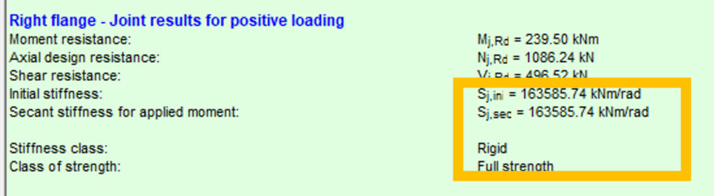
Welded connection
The welded joint behaves as a rigid connection with full strength. Rotational stiffness is high enough that joint deformation has negligible influence on the global structural response. In Consteel, this is reflected by a stiffness value approaching the rigid classification limit defined by the standard. Such connections are typically used where continuity and moment transfer must be ensured without significant rotation.
Using the Joint module, these behaviors can be modeled and evaluated through a structured workflow:
- Joint creation: Define the connection either manually or based on the global structural model using automatic recognition.
- Connection configuration: Assign geometry, cross-sections, bolt layouts, welds, and optional stiffeners.
- Loading definition: Apply either user-defined internal forces or import them directly from the global analysis.
- Analysis: The software evaluates moment resistance, shear resistance, and both initial and secant rotational stiffness using Eurocode-based procedures.
- Integration: The calculated stiffness can be applied back to the global model, enabling second-order effects and realistic force distribution.
Considering rotational stiffness leads to more accurate structural models. Instead of assuming ideal boundary conditions, the engineer can:
- Reduce conservatism in member design
- Capture redistribution effects in frames
- Optimize connection detailing
- Improve overall structural efficiency
This approach is particularly important in steel frames where joint flexibility can significantly affect deflections, internal forces, and stability.
Download the example model and try it!
Download modelIf you haven’t tried Consteel yet, request a trial for free!
Try Consteel for freeDid you know that you could use Consteel to perform dual analysis with 7DOF beam and/or shell elements?
With two advanced features, Superbeam and Convert members to plates, you can choose the approach that best suits your project needs, whether you’re focused on modeling efficiency or detailed analysis.
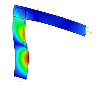
The Superbeam function offers a smart, adaptive way to handle structural members. It enables you to model with the simplicity of standard 7DOF beam elements while allowing you to switch to a more detailed shell-based analysis for specific members whenever needed.
Once the structure is modeled using beam elements, you can select how each member is analyzed:
- Using the beam model, which applies Consteel’s proven 7DOF beam elements along with its comprehensive design tools.
- Or using a shell model, which is automatically generated for selected members. This shell model includes detailing features such as web cutouts and stiffeners, fully integrated into the global analysis model.
This dual approach is fully adaptive. You can continue modifying your model using beam elements and switch between analysis modes as required, offering both speed and precision within the same workflow.
For a complete overview of how to activate and manage Superbeam functionality, refer to the documentation:
Superbeam – Consteel Manual


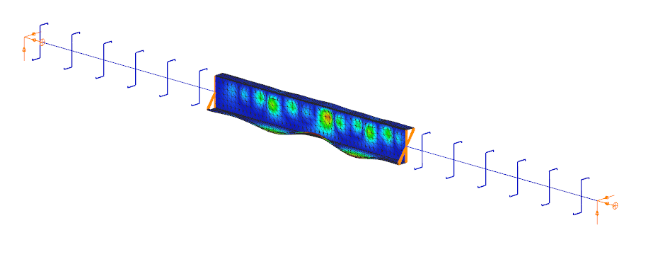
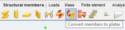
When you need complete control over geometry and mesh, or when shell analysis alone is not sufficient, Consteel provides the Convert members to plates function. This tool allows you to manually transform selected members into actual plate elements, enabling detailed modeling from the start.
Unlike the automatic conversion used in Superbeam, this method performs a permanent, non-reversible transformation (though undo is available during the session). It supports a wide range of section types, including hot-rolled, cold-formed, and welded profiles.
The conversion process preserves and adapts existing connections, eccentricities, loads, and supports. Where needed, rigid bodies and constraint elements are added to maintain structural continuity. These constraints ensure proper transfer of deformations, including warping, between the new plate model and the rest of the structure.
This function is especially useful in cases where precision is critical, such as modeling joints, fabrication-specific details, or complex load interactions.
To learn more, see the full guide here:
Convert Members to Plates – Consteel Manual
Both Superbeam and Convert members to plates serve different purposes, depending on the level of detail and control required in your model:
| Feature | Superbeam | Convert members to plates |
| Workflow | Beam modeling with optional shell analysis | Full plate modeling from the beginning |
| Conversion | Automatic and reversible | Manual and permanent |
| Suitable For | Flexibility in analysis, quick modeling | Full control, high-detail requirements |
| Supported Sections | Welded I and H profiles | Hot-rolled, cold-formed, and welded sections |
| Detailing Support | Cutouts and stiffeners (in shell analysis) | Full geometric detailing, including transitions |
| Design Integration | Integrated with beam-based design tools | Suitable for fabrication-level modeling |
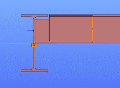
In Superbeam, constraint elements are generated automatically to connect converted shell elements to other members, such as bars. During member-to-shell conversion, these elements link the FE shell nodes to the rest of the model, ensuring accurate deformation transfer.
If the convert members to plate function is applied directly to beam elements, rigid bodies are created at their ends, which is useful for analyzing local behavior but does not transfer warping deformations. If the beam is first converted to a shell and then to plates, hinged rigid edges are placed along the plate boundaries. This arrangement, combined with constraint elements, transfers not only in-plane and out-of-plane deformations but also warping between the shell and the rest of the structure.
Download the example model and try it!
Download modelIf you haven’t tried Consteel yet, request a trial for free!
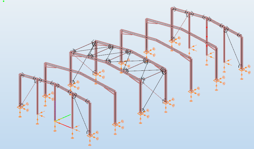
Try Consteel for freeDid you know that you could use Consteel to design web-tapered members?
Tapered members are widely used in the economic design of steel-framed structures, such as industrial halls and warehouses, because they make it possible to save material while still ensuring structural strength and stability. With Consteel’s dedicated Tapered Member function, you can model, analyze, and verify these members efficiently, supporting both everyday engineering practice and advanced stability checks.
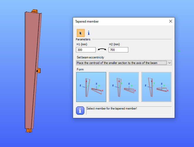
In Consteel, tapered members are line members with welded I or H, box, or cold-formed C sections. Hot-rolled and other macro sections cannot be tapered. Their section height can vary linearly along the member length, making them suitable for realistic structural modeling.
It is best to start with a section close to the smaller end of the taper. The start height (H1) applies at the beginning of the member, and the end height (H2) at the other end. If either value is less than half of the original section height, Consteel automatically resets it to 0.5 times the original. H1 and H2 can be swapped easily with the dedicated icon to reverse the taper direction.
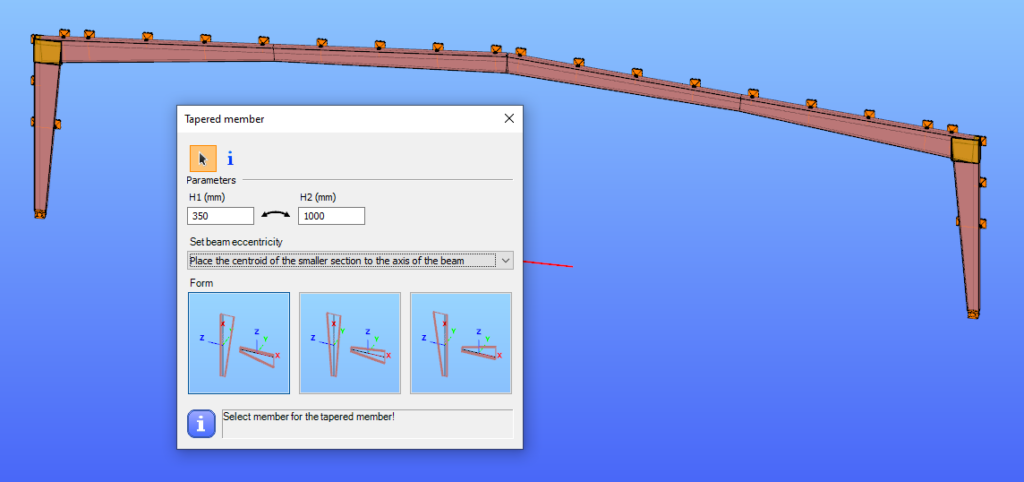
The placement of a tapered member relative to the axis of the original beam is defined by beam eccentricity rules. Consteel offers three alignment options:
- Centroid of the smaller section on the axis – the tapering develops outward from the end with the smaller height.
- Centroid of the larger section on the axis – the bigger end of the member remains fixed to the original axis.
- Centroid of the original section on the axis – one edge of the tapered member coincides with the original section, and the tapering starts from this position.
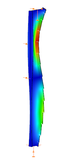
In analysis, Consteel creates tapered sections with the specified start and end heights and places them on the member’s reference line. Unless symmetric tapering is used, this placement is eccentric, which introduces additional effects. At frame joints, for example, extra moments from eccentric axial forces must be considered to maintain equilibrium.
Consteel handles these effects automatically, ensuring realistic results. Symmetric tapering keeps the analysis simpler, while eccentric tapering requires more attention. In all cases, global stability checks should complement sectional verifications to guarantee structural safety.
Download the example model and try it!
Download modelIf you haven’t tried Consteel yet, request a trial for free!
Try Consteel for freeDid you know that you could use Consteel to consider connection stiffness for global analysis?
One of Consteel’s unique strengths is its ability to integrate joint modeling and calculation directly into the global analysis.
The Joint module performs all analyses in line with the standard procedures of Eurocode 3 Part 1-8, covering almost the entire scope of the code. This ensures results that are both reliable and fully compliant, across a wide range of connection types such as: Moment connections, Shear connections, Hollow section connections.
Modern structural design increasingly considers the mechanical interaction between the global model and its joints — whether rigid, semi-rigid, or pinned.
If you’d like to dive deeper into how semi-rigid joints influence structural behavior and stiffness classification, check out our detailed article: Semi-rigid joints in modeling of structures.
This integrated approach leads to results that are both more realistic and more economical, but it also requires more sophisticated modeling. Consteel makes this process straightforward:
- Joints can be created manually or automatically based on the model geometry.
- The create joint by model function examines member positions and cross-sections, then offers suitable joint types.
- Once defined, the joint can be placed into the global model, and its connection stiffness can be included in the global analysis.
- After placement, the joint is always rechecked against the latest analysis results.
In order to consider the connection stiffness of the placed joint, open the analysis parameters, tick the Include connection stiffness checkbox, and rerun the analysis.
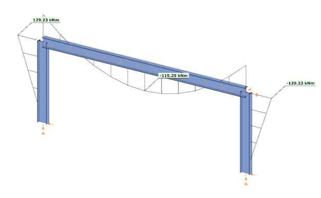
Let’s explore how the behavior of a simple frame changes under different connection assumptions:
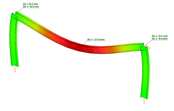
In the first case, where no actual connection stiffness was considered and the members were assumed to have continuous rigid ends, the results showed a bending moment (My) of 129.23 kNm at the column upper end and 115.25 kNm at the beam midspan. The corresponding deflection in the beam’s midspan (z-direction) was –17.4 mm.
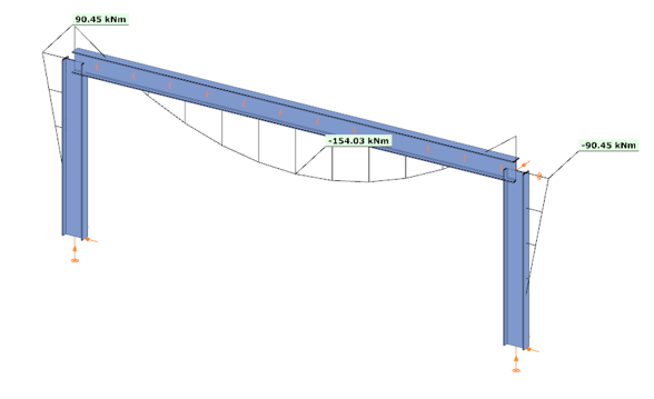
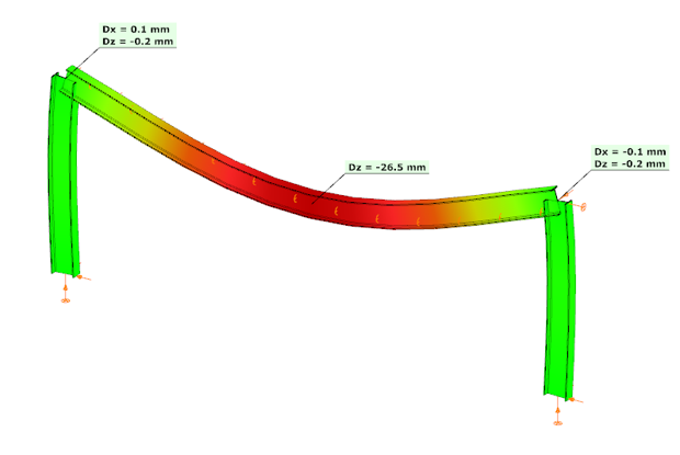
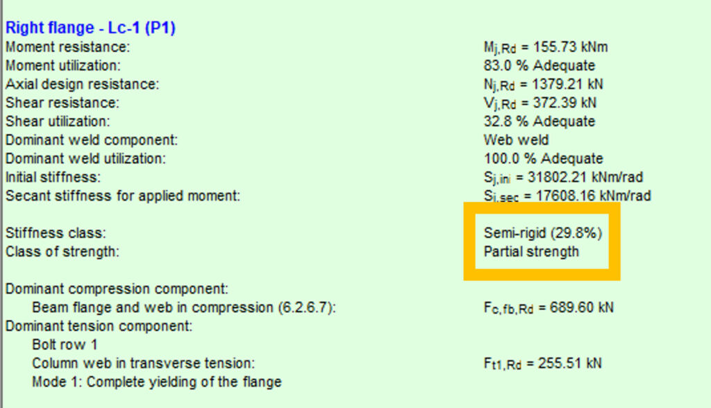
In the second case, the connections were modeled with their actual semi-rigid stiffness of 29.8% and partial strength. Here, the bending moment at the column upper end decreased to 90.45 kNm, while the beam midspan moment increased to 154.03 kNm. The beam midspan deflection reached –26.5 mm, representing an increase of 52% compared to the rigid assumption.

In the third case, with a higher semi-rigid stiffness of 53.6% and partial strength, the results balanced between the two extremes: the column end moment was 104.37 kNm, the beam midspan moment was 140.11 kNm, and the midspan deflection was –23.2 mm. This corresponds to an increase of 33% in deflection compared to the rigid assumption.
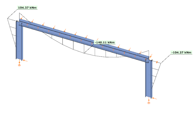
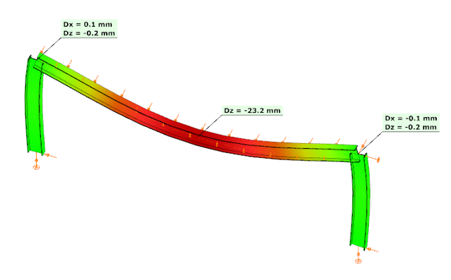

These examples clearly demonstrate how connection stiffness significantly influences global structural behavior. Assuming rigid connections may underestimate beam deflections and distort moment distribution, while considering realistic semi-rigid stiffness, provides a more accurate representation of structural performance.
Download the example model and try it!
Download modelIf you haven’t tried Consteel yet, request a trial for free!
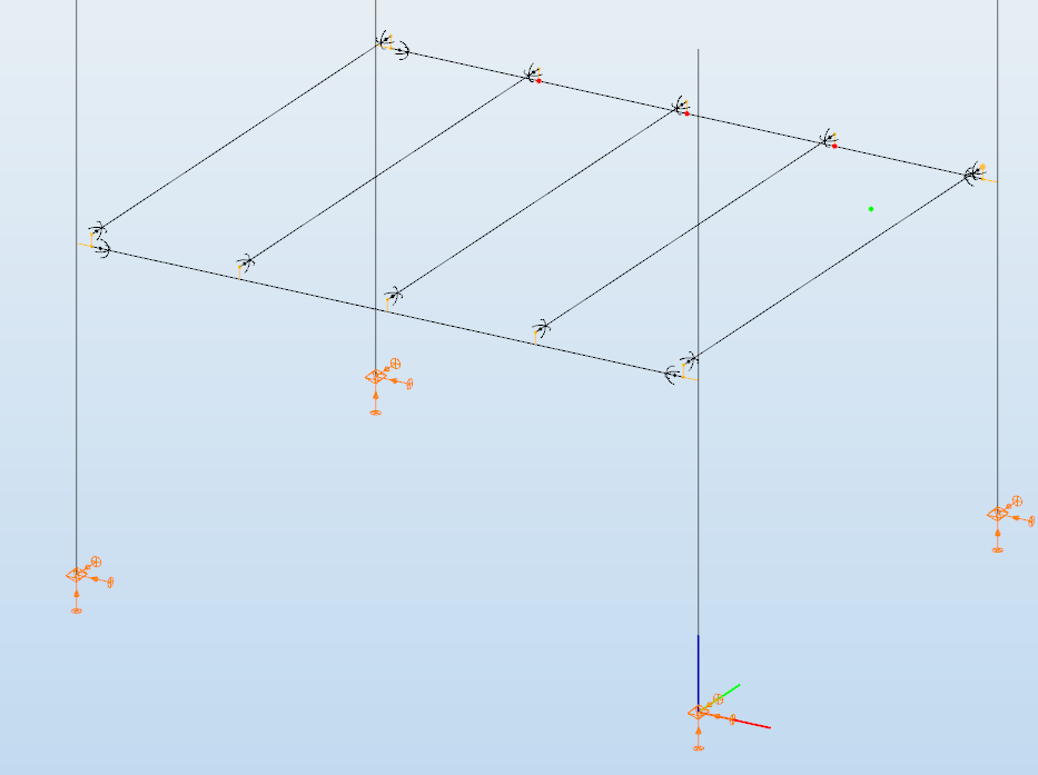
Try Consteel for freeDid you know that you could use Consteel to determine the optimum number of shear connectors for composite beams?
In composite beam design, the required number of shear studs is not only a detailing issue but a direct part of the structural resistance mechanism. The modelling and design environment in Consteel allows this number to be determined in a rational and automated way, consistent with EN 1994-1-1:2010.
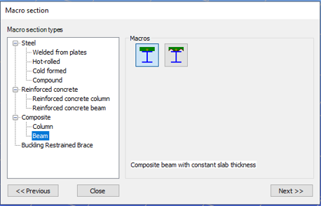
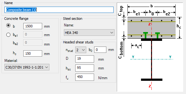
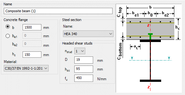
The process begins with the definition of a composite beam cross-section (Macro section). Two standard types are available: a solid slab composite beam and a profiled steel sheeting composite beam. The effective width is defined at input level, but the actual effective width used in analysis is calculated automatically based on span, geometry, and stud spacing assumptions. This ensures that the structural response is captured realistically, while maintaining simple input control for the user.
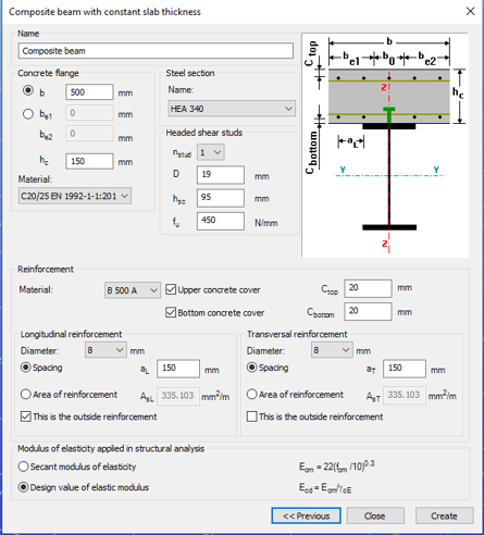
After defining the cross-section, the member is created and design parameters are assigned through object properties. These parameters govern key aspects of composite behaviour, including stud spacing, support conditions, and whether shear stud design is performed manually or automatically.
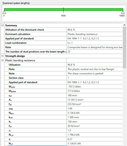
For shear connector design, Consteel applies a plastic distribution model. The governing section of the beam, typically corresponding to the maximum bending moment, is identified automatically. From this section, shear studs are distributed symmetrically along the beam length.
When automatic optimisation is selected, the software determines the minimum number of shear studs required to satisfy bending resistance. It then increases the number iteratively until the composite section achieves sufficient capacity. The resulting value represents the optimal number of shear connector positions for the given loading and geometry.

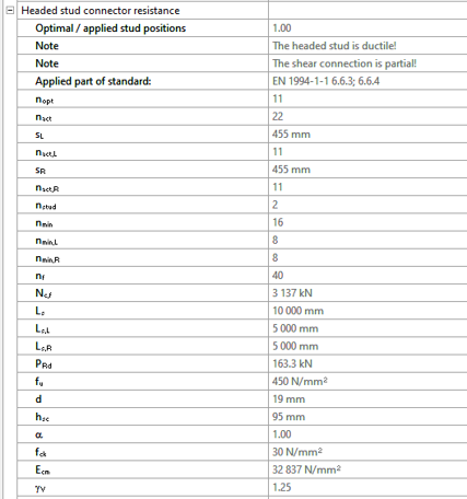
The key parameters used in this evaluation include:
- nopt: optimal number of shear stud positions in the governing region
- nact: actual number of stud positions applied
- sL, sR: spacing of studs on the left and right side of the critical section
- nmin: minimum required number of stud positions based on resistance
The ratio nact / nopt is used as a direct measure of utilisation of the shear connector system.
There is also the option to define the number of studs manually. In that case, Consteel distributes them uniformly along the member and checks compliance with detailing rules such as minimum and maximum spacing. This is typically useful when construction constraints or predefined detailing standards take priority.
Composite beam design itself is carried out according to EN 1994-1-1:2010. Plastic bending resistance is evaluated for Class 1 and 2 cross-sections, while shear, concrete flange crushing, and longitudinal shear are checked at critical sections. Shear buckling is treated according to EN 1993-1-5. Lateral-torsional buckling is not included in the current design scope.
For profiled sheeting, shear stud resistance is reduced depending on rib orientation, in line with Eurocode 4 rules.
Overall, the key point is that the number of shear connectors is no longer an assumed input. It is derived from structural demand through an automated and transparent process, which makes it easier to reach an efficient and consistent composite design without repeated manual iteration.
Download the example model and try it!
Download modelIf you haven’t tried Consteel yet, request a trial for free!
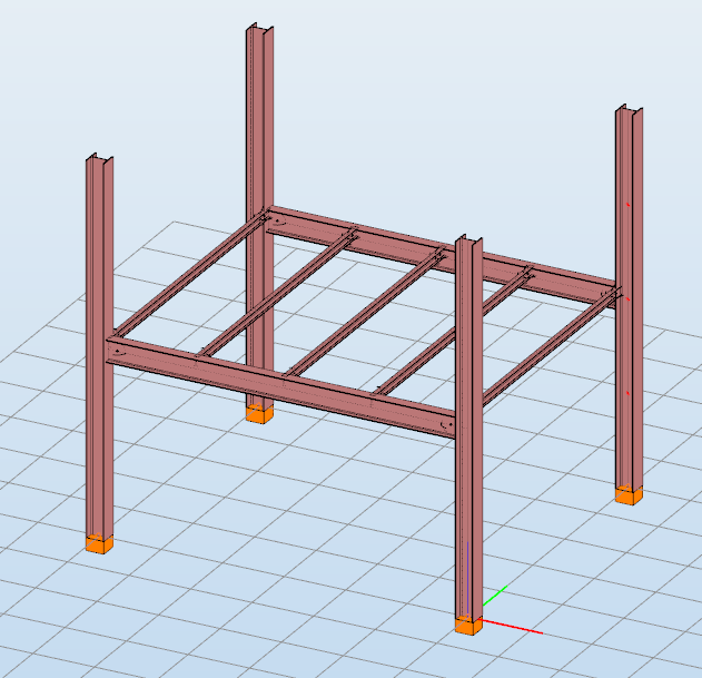
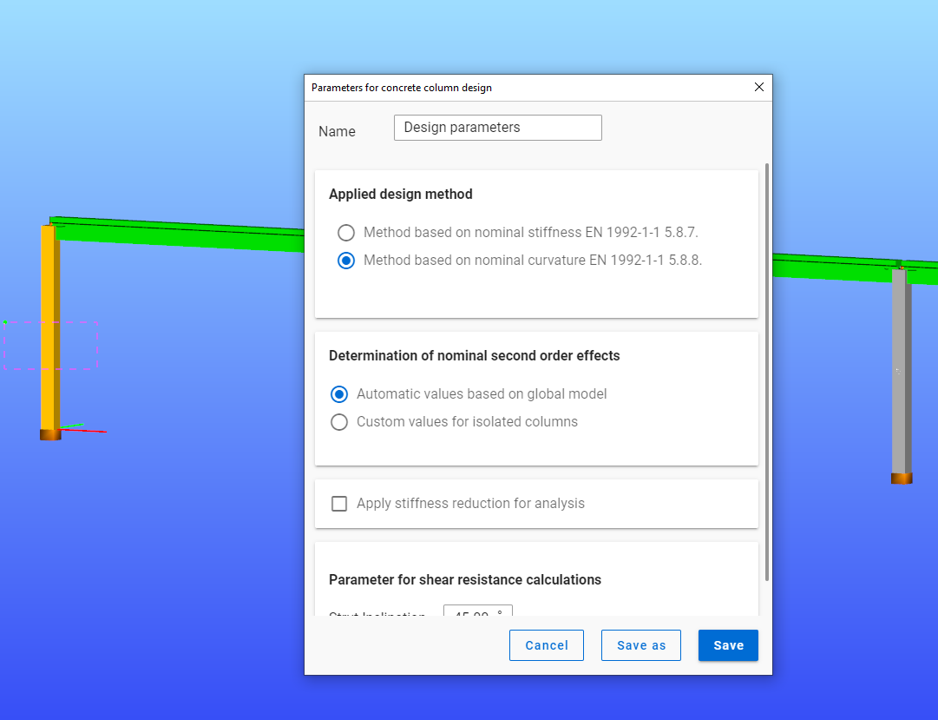
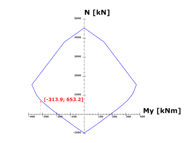
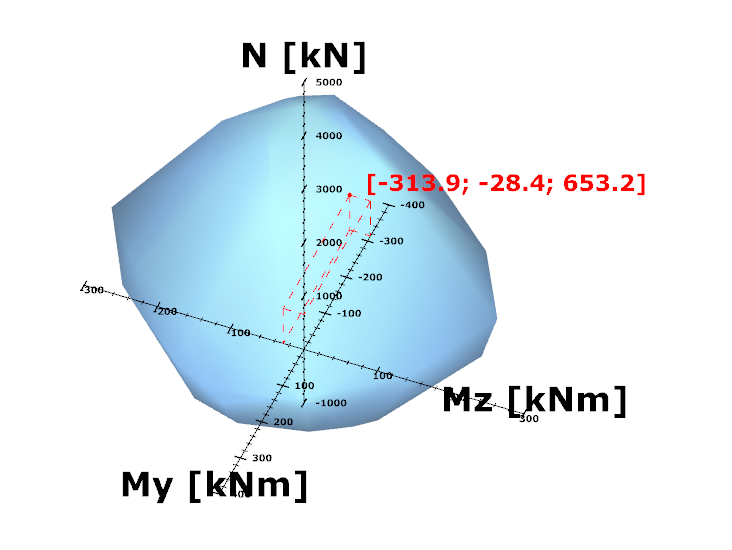
Try Consteel for freeDid you know that you could use Consteel to determine automatically the second order moment effects for slender reinforced concrete columns?
Download the example model and try it!
Download modelIf you haven’t tried Consteel yet, request a trial for free!
Try Consteel for free
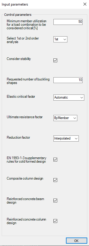
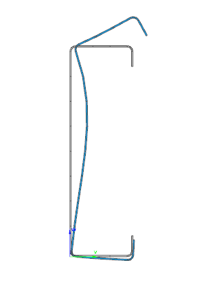
Did you know that you could use Consteel to perform local and distortional buckling checks for cold-formed members?
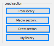
First, sections must be loaded into the model. To load cold-formed sections, you can choose from four options: From library, Macro section, Draw section, or My library.
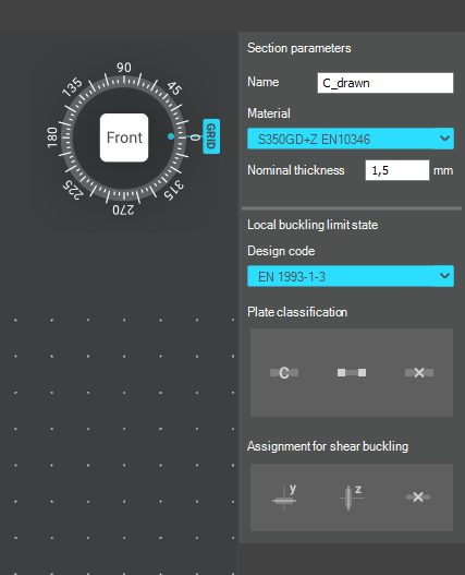
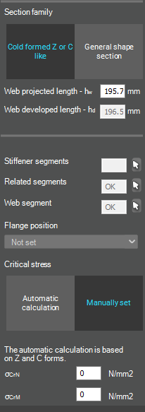
After the first-order and buckling analyses are completed, you can proceed to the Ultimate limit state check settings and enable the steel design cross-section and buckling checks. At the bottom of the steel design section, there is an option to Consider the supplementary rules from EN 1993-1-3 for the design of cold-formed sections. This checkbox must be selected if you want to design cold-formed sections.
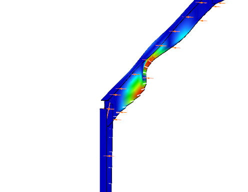
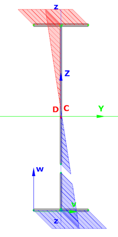
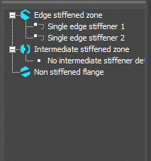
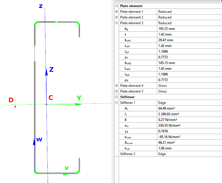
When the calculation is finished, by opening the Section module, we can review all the properties of the Effective section of the elastic plate segment model. By opening each plate element, we can verify the length, effective length, thickness, effective thickness, slenderness, and reduction factor separately. In addition, the properties of the stiffeners can also be verified: area, moment of inertia, lateral spring stiffness, critical stress, reduction factor, compressive stress, reduced effective area, and reduced thickness.
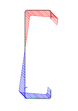
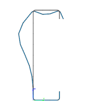
Similarly, the stresses can also be checked from the Properties tab. In the colored figure or diagram view, all the calculated stresses can be seen together with their resultants.
Consteel automatically takes into account the effect of distortional buckling when calculating the effective sections of cold-formed thin-walled sections.
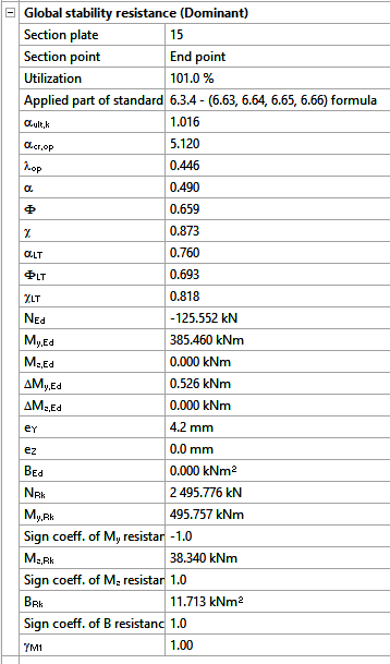
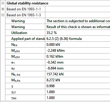
Moving on to the Standard resistance tab in the Section module, all calculated results can be verified, not only the dominant one. By opening the Global stability resistance check, we can see that, since we enabled the option to consider the supplementary rules from EN 1993-1-3 for the design of cold-formed sections, results are available both according to EN 1993-1-1 and according to EN 1993-1-3.
Download the example model and try it!
Download modelIf you haven’t tried Consteel yet, request a trial for free!
Try Consteel for free