Did you know that bar members can be included in load distribution even when slightly offset from the surface, by using a Load Transfer Surface with a user-defined tolerance?
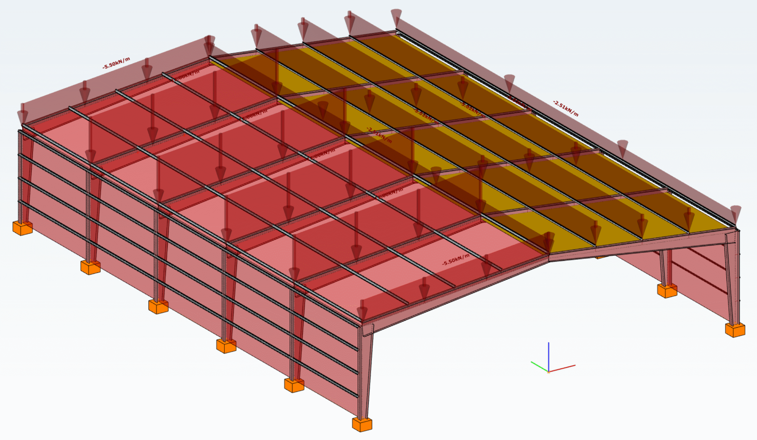
A Load transfer surface (LTS) is a special type of surface that converts surface loads into line loads and distributes them to structural members. This is particularly useful when surface loads, such as floor loads, snow loads, or wind loads, need to be transferred to supporting members.
In order to use the meteorological load generator function or our fluid-dynamics-based universal wind load generation tool, FALCON, the load transfer surfaces (LTS) on the structure must intersect, they must meet along a common edge. Otherwise, the results will not be accurate.
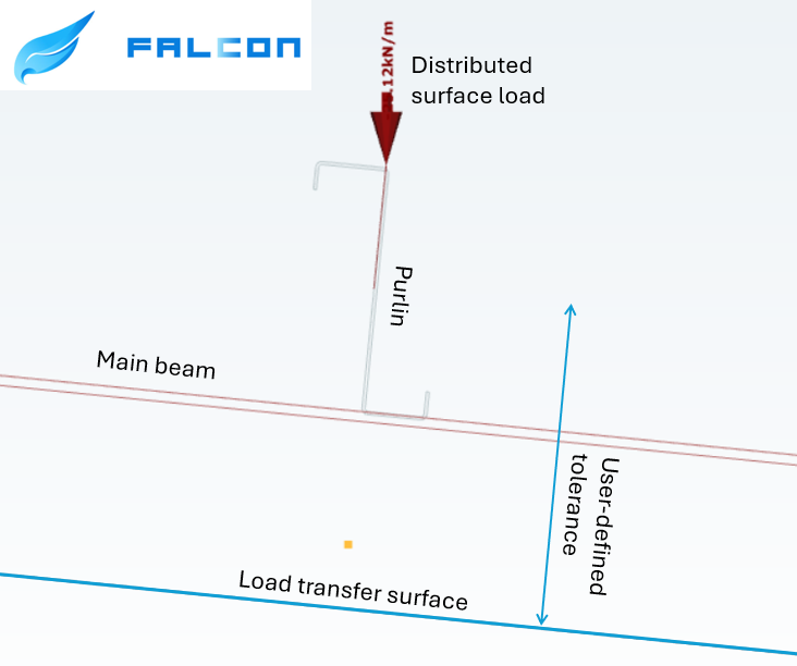
This creates a problem when, for example, the purlins take over the meteorological loads from the sheets or panels, but their planes do not intersect. In this case, the LTS is applied to the plane of the main structure, while the members assigned to it may lie within a specified distance from that plane.
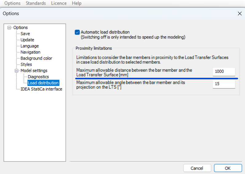
To define the tolerance for the load transfer surface, first go to the Options menu. There, you can set the maximum allowable distance between the bar members and the load transfer surface. In this example, all members that are less than 1000 mm from the surface can be assigned to the load transfer surface.
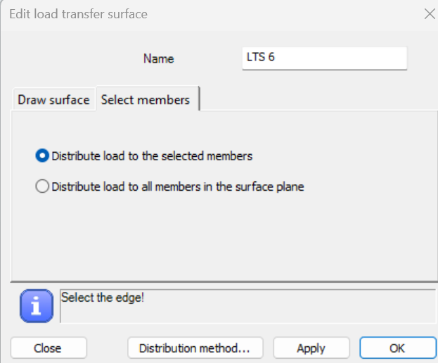
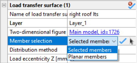
In order to be able to manually select the members attached to the load transfer surface, when defining it, make sure that in the Select members section you choose the Distribute load to the selected members option. If this option was not selected initially, you can set it later by selecting the surface and defining the member selection in the Object Properties window.
In the example model below, observe how the load distribution changes from the main beams (left side) to the tops of the purlins (right side) by introducing a user-defined tolerance and assigning the appropriate members to receive the load from the roof.
Download the example model and try it!
Download modelIf you haven’t tried Consteel yet, request a trial for free!
Try Consteel for freeProgram verzió: Consteel 17; Build 3303
Tervezés célja, tervezési szabvány kiválasztása
A jelen tervezési segédlet a kezdő ConSteel 17 felhasználó számára egy kéttámaszú rácsos tartó tervezését mutatja be, lépésről lépésre. Az építészeti koncepcionális tervből ismert a megtervezendő rácsos tartó geometriai kialakítása (1. ábra). A koncepció szerint a rácsos tartó övei HEA120 típusú melegen hengerelt szelvényből készülnek, míg a rácsrúdjai hidegen alakított SHS80x4 szelvényből. A jelen segédletnek a csomópontok tervezése nem része.

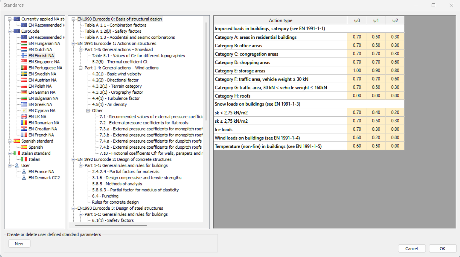
Ismert, hogy a szerkezettervezés mindig valamely szabvány, illetve annak változata szerint történik. A szabvány kiválasztása új modell létrehozásakor a Project centerben a Tervezési szabvány menüből választható, vagy később a Szabványok rendszerfül [S1] kiválasztó paneljében módosítható (2. ábra).

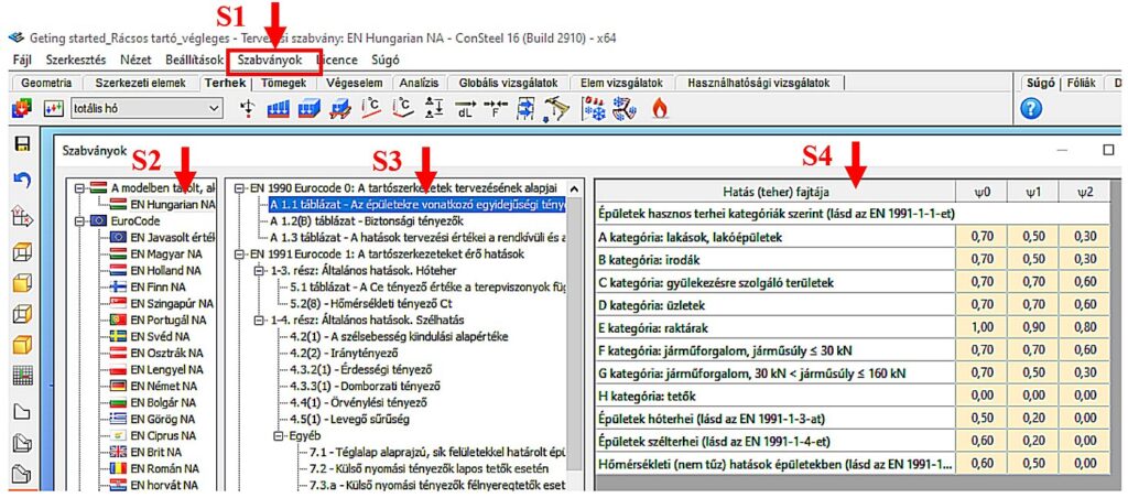
Az alkalmazni kívánt tervezési szabvány a panel bal oldali listájából választható ki. Jelen esetben az EN Hungarian NA opciót [S2] választjuk (MSz EN Magyar Nemzeti melléklet). A kiválasztott szabvány által alkalmazott paraméterek a középső tartalomjegyzék megfelelő sorának kiválasztásával érthető el, a jobb oldali táblázatban [S4]. A 2. ábrán az EC0 szabvány 1.1 táblázatának megfelelő egyidejűségi tényezők kerültek kiválasztásra, amely paramétereket a jobb oldali táblázat mutatja meg.
Szerkesztő raszter beállítása
Először állítsuk be a raszter méretét a szerkezet fesztávjának megfelelően. Ehhez alkalmazzuk a baloldalon található eszközcsoport megfelelő gombját [1], amelynek hatására megjelenik a Raszterháló és koordinátarendszer beállító panel (2. ábra).
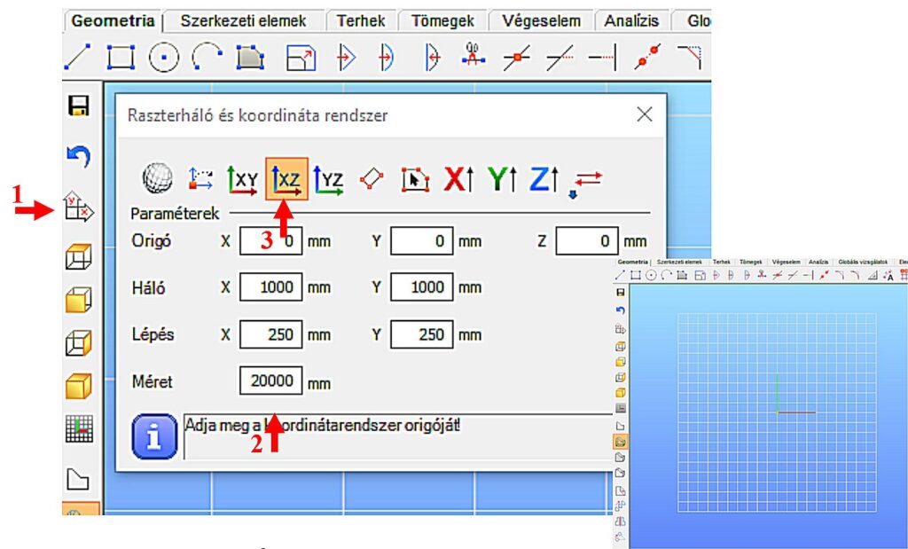
Például a 19.6m hosszú tartó esetén a Méret ablak tartalmát 20000 milliméterre állíthatjuk [2]. A beállítás aktualizálásához nyomjuk meg az Enter-t, vagy zárjuk be az ablakot. A fenti beállítás esetén a raszter X és Y irányban 20 méter széles lesz, a raszter vonalak sűrűsége 1000 mm, a lépésközök 250 mm. A rácsos tartó modellt célszerű az X-Z globális koordináta síkban felvenni, tehát a szerkesztő rasztert el kell fordítanunk az X-Z síkba. Ehhez válasszuk XZ sík opciót [3].
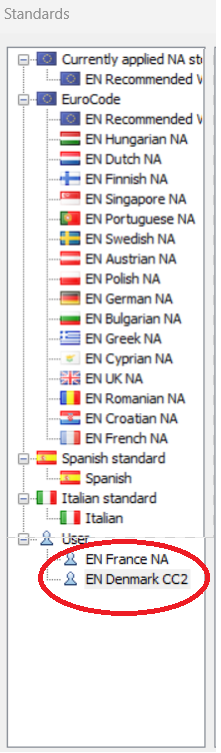
gateDid you know that Consteel already supports most of the countries which have adopted Eurocode design standard? If your country would still be missing, no problem, you can create your own NA settings. This is useful also in the case when you want to customize the recommended settings based on your own preference.
If you haven’t tried Consteel yet, request a trial for free!
Try Consteel for free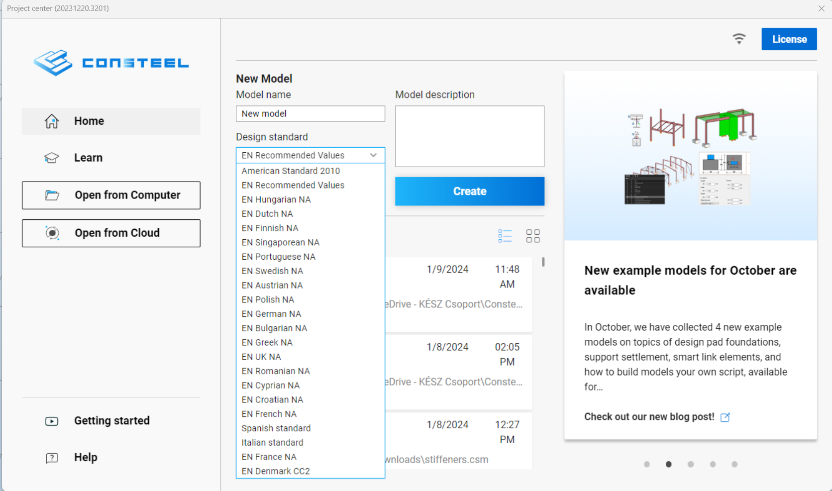
Geometry definition
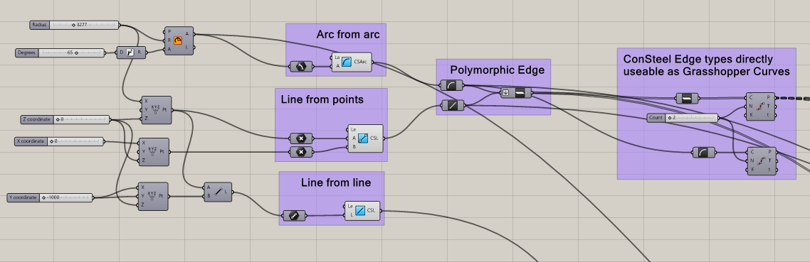
Geometry in Pangolin can be described by lines or circular arcs and polygons made up of the former two. The relevant components are the simplest ones, acting as converters from the native Grasshopper geometry types, with the possibility of specifying a Consteel Layer.
Section definition
The geometry definition of the sections is more refined since Consteel uses detailed section models composed of solid representation for analysis and thin-walled representation for standard design checks. There are two options to create sections in Pangolin: use a predefined section from the section bank or create custom sections by predefined parametric macros.
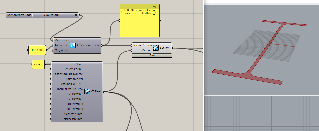
Predefined sections from section bank
7000+ different profiles can be defined from the section bank (hot-rolled, cold-fromedetc.). This workflow contains two steps: 1. Getting the section preview from the bank. 2. Getting the actual section from the preview. (The reason for this is the performance, as in Pangolin sections are real objects, loading all the 7000+ sections from our bank would take minutes even on a powerful pc.) The section bank component provides various filtering options, to help select the section. After the desired section preview is selected, you can create a real section from it along with a material, and check the cross-section surface in Rhino.
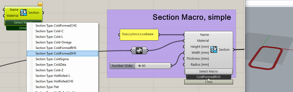
Custom sections based on predefined macros
This workflow consists of placing a section macro component, selecting a base macro, and defining the macro parameters.
One of the most important unique features of Consteel is its advanced analysis and design calculations for members with cold-formed sections having various stiffeners. Correspondingly Pangolin makes it possible to create custom cold-formed sections, with custom stiffeners parametrically:
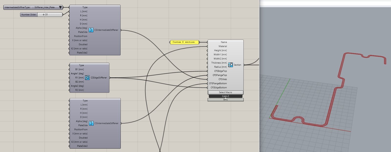
As you can see, the components help in building complex sections with available default values providing a wide range of parameters to be customized.
Structural member definition
Defining beams is as easy as pulling the reference edges and the beam section into the Beam component:
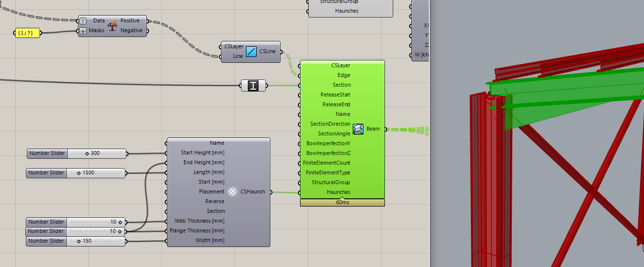
In the example above we also defined a haunch on the beam ends, another unique feature of Consteel, which will be taken accurately into account during analysis and design.
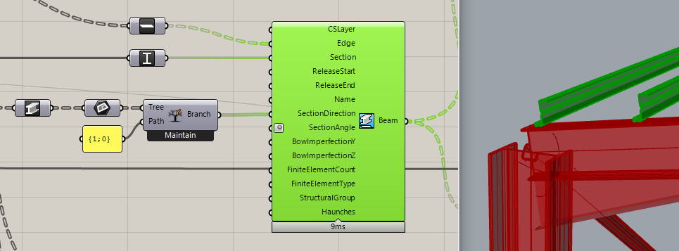
To make modelling easier, Pangolin also provides several useful implicit data conversions, like in the picture above: at the start, we have the IPE 300 beams, and just connecting them into a Grasshopper Plane parameter, the beams get converted to their local coordinate systems. This plane can be directly connected with the Z purlins section direction parameter to correctly lay them upon the main beams.
Structural details
Let us stop at the purlins for a moment! Pangolin also provides a detailed linking of structural objects through Consteel’s link elements which can be rather important in order to consider accurately the lateral restraint effect on the beam provided by the purlins.

The definition of link elements includes setting the interface position, the direction, and the stiffness attributes of the connection. Defining supports for the model is also helped by automatic conversions, where you can directly ask a beam’s endpoint, and place the support there, instead of manipulating with indexes through a complex definition.
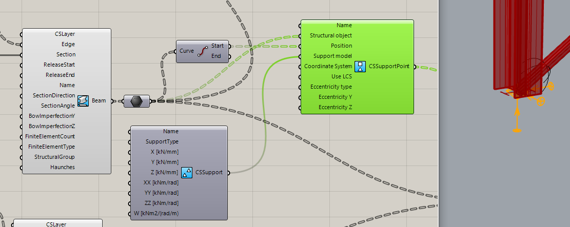
Pangolin also provides the possibility to define edge and plate supports.
Load definition
gateConsteel 14 is a powerful analysis and design software for structural engineers. Watch our video how to get started with Consteel.
Contents
- Creating snapshots
- Save tables for documentation
- Create section and joint design documentation
- Create model documentation
- Insert snapshots and tables into the documentation
Consteel 14 is a powerful analysis and design software for structural engineers. Watch our video how to get started with Consteel.
Contents
- Build joint model based on the global model
- Bolted moment end-plate connection design
- Base plate connection design
- Apply connection stiffness in analysis
Consteel 14 is a powerful analysis and design software for structural engineers. Watch our video how to get started with Consteel.
Contents
- Set design parameters
- Perform cross section check
- Examine the design results in the Section Module
- Stability design according to the general method
- Member check – stability design for members
- Serviceability check
Consteel 14 is a powerful analysis and design software for structural engineers. Watch our video how to get started with Consteel.
Contents
- Set analysis parameters
- Perform first and second order analysis
- Perform buckling analysis
- Analysis results in graphics and in tables
- Results: deformation, internal forces, reactions
Consteel is a powerful analysis and design software for structural engineers. Watch our video how to get started with Consteel.
Contents
- Define load groups and load cases
- Generate load combinations
- Define line loads globally
- Define partial line loads locally
Consteel is a powerful analysis and design software for structural engineers. Watch our video how to get started with Consteel.
Contents
- Load sections
- Creating beams and columns
- Place supports
- Haunch definition
- Frame corner definition