Did you know that you could use Consteel to Consider the shear stiffness of a steel deck as stabilization for steel members?
Download the example model and try it!
Download modelIf you haven’t tried Consteel yet, request a trial for free!
Try Consteel for free
Introduction
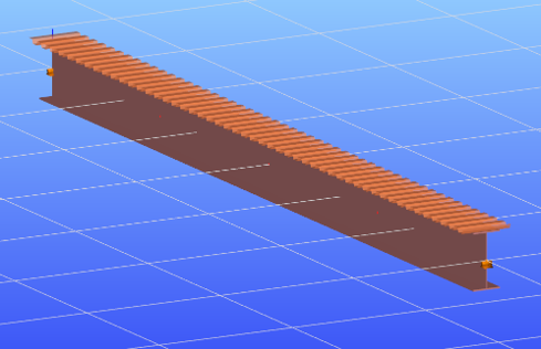
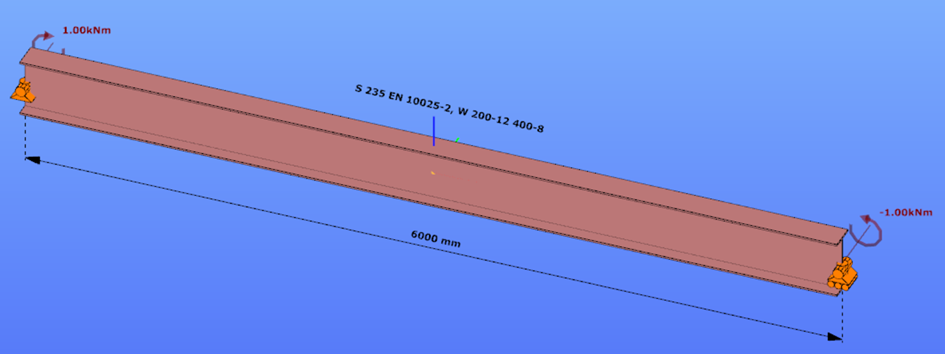
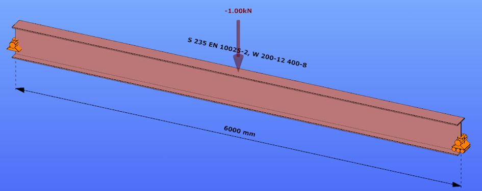
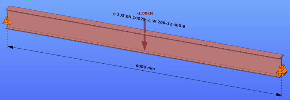
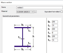
This verification example studies a simple fork supported beam member with welded section (flanges: 200-12; web: 400-8) subjected to bending about major axis. Constant bending moment due to concentrated end moments and triangular moment dsitribution from concentrated transverse force is examined. Critical moment and force of the member is calculated by hand and by the Consteel software using both 7 DOF beam finite element model and Superbeam function.
Geometry
Constant bending moment distribution
Triangular bending moment distribution – load on upper flange
Triangular bending moment distribution – load on bottom flange
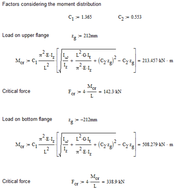
Calculation by hand
Constant bending moment distribution

Triangular bending moment distribution
Computation by Consteel
Version nr: Consteel 15 build 1722
Constant bending moment distribution
7 DOF beam element
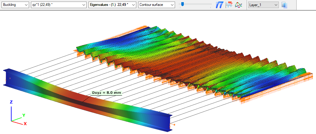
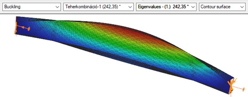
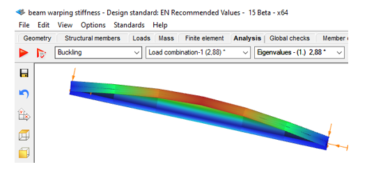
First buckling eigenvalue of the member which was computed by the Consteel software using the 7 DOF beam finite element model (n=16). The eigenshape shows lateral torsional buckling.
Superbeam
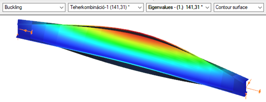
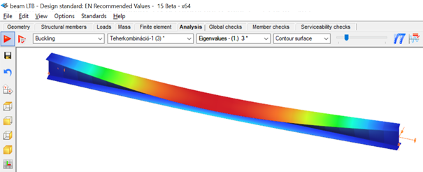
First buckling eigenvalue of the member which was computed by the Consteel software using the Superbeam function (δ=25).
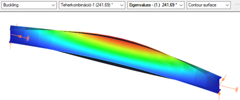
Triangular bending moment distribution – load on upper flange
7 DOF beam element
First buckling eigenvalue of the member which was computed by the Consteel software using the 7 DOF beam finite element model (n=16).
Superbeam
First buckling eigenvalue of the member which was computed by the Consteel software using the Superbeam function (δ=25).

Triangular bending moment distribution – load on bottom flange
(tovább…)Introduction
During the lifetime of a steel structure changes often happen. These changes usually result an increase of loads acting on some of its elements which therefore may need to be strengthened.
Strengthening is usually done by welding additional steel plates to the existing members. In the case of I sections, usually, the flanges are reinforced to increase the bending moment capacity or the web is stiffened to avoid local buckling or crippling at support regions.
This paper will focus on the increase of bending moment capacity.
Lateral-torsional buckling resistance
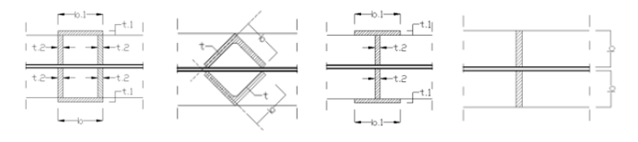
The usual practice is to either increase the compression flange thickness by adding additional plates to it, or by widening it with the help of angles, as can be seen in the pictures below.
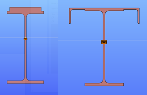
Although these can be very efficient ways to increase the bending moment capacity of a beam, welding on site is a complex process and might require the temporary removal of structural or non-structural elements connected to the flange of the beam. Welding especially “above the head” is difficult, the quality of weld seam needs to be properly checked.
Bending moment capacity of a beam might be limited by lateral-torsional buckling. If the section is not sufficiently restrained laterally against torsion, its actual load-bearing capacity will be lower than the value which depends purely on its section resistance.
In such cases, if the LTB behaviour could be directly improved, there would be no need to strengthen its cross-section along its full length. Here comes the Superbeam as a possible help.
Additional lateral restraining elements are often difficult to be added, therefore this is often not an option.
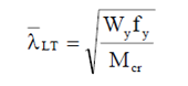
If we look at what LTB resistance of an I section depends on, we can see, that if we don’t want to change its cross section along its full length, it depends on the value of the reduction factor responsible to consider lateral-torsional buckling χLT.
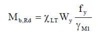
This reduction factor is calculated from the slenderness value of the beam, which needs to be improved (reduced) to result a lower, more favourable reduction factor.
Without changing the cross section, the only way to do this is by improving the critical moment value. Increasing this value can be made not only by changing the cross-section but also by changing the boundary conditions.
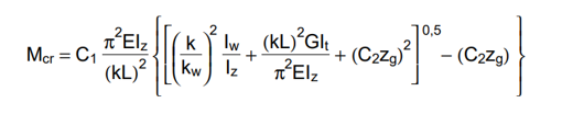
The value of parameters ‘k’ and ‘kw’ depend on the boundary conditions, where ‘k’ means a factor which depends on how the section is fixed against weak axis bending at its ends and ‘kw’ means a factor which depends on how the section is fixed against warping. Warping is the phenomenon when the upper and lower flange of an I section twist in opposite directions.
To change the end conditions is typically difficult, but a certain limitation of the twist of flanges relative to each other ie. preventing or limiting warping might be possible. Limitation of this twist can be obtained by connecting the flanges by an additional element which has non-zero torsional stiffness. This torsional stiffness will prevent the counter-rotation of the flanges and therefore the warping and allowing to consider a ‘kw’ value different than 1.0 in this formula.
Consteel supports several such strengthening profiles and can determine the torsional stiffness to be considered in preventing or limiting warping.
Analysis with Consteel Superbeam
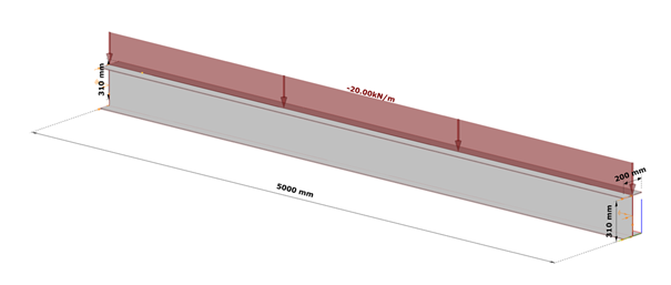
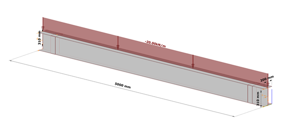
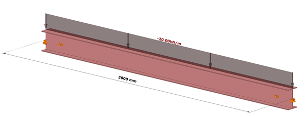
Let’s take the following case. We have a simple supported 5 m long beam loaded by a uniform load of 20 kN/m acting at the top flange, on top of its self weight, without any intermediate lateral support. Its section is a welded I profile, made of S235, 10 mm thick plates, flange width of 200 mm and total section depth of 320 mm.
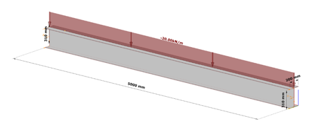
As we can expect, in the case of such a large unbraced length, the bending moment resistance would be strongly limited by lateral-torsional buckling, and therefore we can expect that strengthening by the proposed method is viable.
The critical moment of this beam is obtained in Consteel using linear buckling analysis with 7DOF beam elements option of the Superbeam, which has found the critical multiplier of 2.88.
This results Mcr = 2.88*64.18=184,84 kNm and a slenderness λ of 1,036 and reduction factor of 0,519.
The final bending moment resistance is 103 kNm.
Let’s further assume that this resistance needs to be increased by 30% due to new requirements. Let’s see whether a successful strengthening without modifications of the cross-section would be possible.
gateIntroduction
Are you wondering how a web opening would influence the lateral-torsional buckling resistance of your beam? Check it precisely with a Consteel Superbeam based analysis
It is often required to let services pass through the web of beams. In such cases the common solution is to provide the required number of opening in the webplate. Such an opening can have a circular or rectangular shape, depending on the amount, size and shape of pipes or ventilation or cable trays.
Beams must be designed to have the required against lateral-torsional buckling. The design procedure defined in Eurocode 3 is based on the evaluation of the critical bending moment value which provides the slenderness value, needed to calculate the reduction factor used for the design verification.
There is no analytical formula provided in the code for beams with web openings. Would the neglection of such cutouts cause a miscalculated and unsafe estimation of the critical moment value?
The following demonstration will be made with a 6 meters long simple supported floor beam with a welded section.
Exposed to a linear load of 10 kN/m, the critical bending moment value of the solid web beam can be obtained by performing a Linear Buckling Analysis (LBA) with Consteel.
The obtained critical multiplier for the first buckling mode is 3.00 which means that the actually applied load intensity can be multiplied by 3.00 to reach the critical load level. The corresponding critical moment will have the value of Mcr = 3.0 * 47.18 = 141.54 kNm yielding a slenderness of 1.286 (Mpl,Rd = 234.20 kNm) and a lateral-torsional buckling resistance of 0.394 * 234.20 = 92.27 kNm. With this value the actual utilization ratio is at 51%.
How would this value change if a rectangular opening needs to be cut into the web of this beam?
Analytical formula for critical bending moment
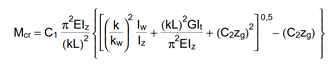
By looking to the analytical formula (ENV 1993-1-1 F.4) to calculate the critical moment of double symmetric sections loaded at eccentric load application point it becomes obvious that the section properties having effect on the moment value are Iz, Iw and It.
An opening in the web has no effect on the first two values and has very little effect on the last one. As it has been already shown in previous article, the presence of such an opening can have effect on the vertical deflection, but as long as the lateral stiffness of a beam is much lower than it’s strong axis stiffness, the vertical deflections can be neglected when the lateral-torsional buckling resistance is calculated. The usual linear buckling analysis (LBA) performed also by Consteel neglects the pre-buckling deformations.
Therefore one can expect that in general web openings can be disregarded when the critical moment value is calculated.
Analysis with Consteel Superbeam
Beam finite elements cannot natively consider the presence of web openings. In order to obtain the precise analysis result, it is possible to use shell finite elements. The new Superbeam functionality comes as a solution in such cases. Instead of using beam finite elements, let’s use shell elements!
Opening can be positioned easily along the web, either as an individual opening or as a group of openings placed equidistantly. The opening can be rectangular, circular or even hexagonal. Circular openings can be completed with an additional circular ring stiffener.
The rectangular opening for this example can be easily defined with this tool. As there is no need to provide any additional opening on the remaining part of the beam, only the first part which includes the opening will be modelled with shell elements and the rest can still be modelled with beam finite elements. Using this technique, the total degrees of freedom of the model can be kept as low as possible. When using Superbeam, the designer has the choice whether to use beam or shell finite elements, as appropriate.
gateTheoretical background
According to the beam-column theory, two types of torsional effects exist.
Saint-Venant torsional component
Some closed thin-walled cross-sections produce only uniform St. Venant torsion if subjected to torsion. For these, only shear stress τt occurs.
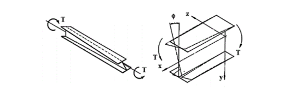
The non-uniform torsional component
Open cross-sections might produce also normal stresses as a result of torsion.[1.]
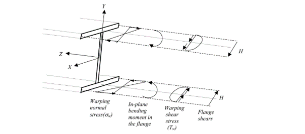
Warping causes in-plane bending moments in the flanges. From the bending moment arise both shear and normal stresses as it can be seen in Fig. 2 above.
Discrete warping restraint
The load-bearing capacity of a thin-walled open section against lateral-torsional buckling can be increased by improving the section’s warping stiffness. This can be done by adding additional stiffeners to the section at the right locations, which will reduce the relative rotation between the flanges due to the torsional stiffness of this stiffener. In Consteel, such stiffener can be added to a Superbeam using the special Stiffener tool. Consteel will automatically create a warping support in the position of the stiffener, the stiffness of which is calculated using the formulas below. Of course, warping support can also be defined manually by specifying the correct stiffness value, calculated with the same formulas (see literature [3]).
The following types of stiffeners can be used:
- Web stiffeners
- T – stiffener
- L – stiffener
- Box stiffener
- Channel –stiffener
The general formula which can be used to determine the stiffness of the discrete warping restraint is the following:
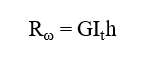
where,
Rω = the stiffness of the discrete warping restraint
G = shear modulus
GIt = the Saint-Venan torsional constant
h = height of the stiffener
Effect of the different stiffener types
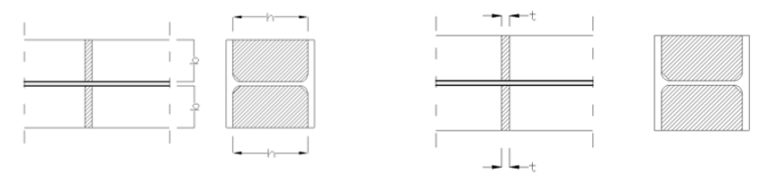
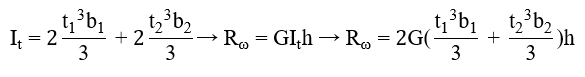
Web stiffener
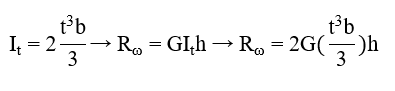
where
b = width of the web stiffener [mm]
t = thickness of the web stiffener [mm]
h = height of the web stiffener [mm]
T – stiffener
where
b1 = width of the battens [mm]
t1 = thickness of the battens [mm]
b2 = width of the web stiffener [mm]
t2 = thickness of the web stiffener [mm]
h = height of the web stiffener [mm]
L-stiffener
where
b = width of the L-section [mm]
t = thickness of the L-section [mm]
h = height of the L-section [mm]
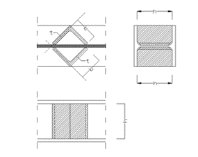
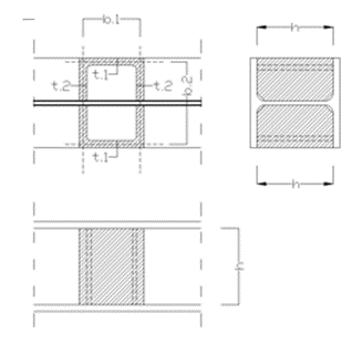
Channel stiffener
where
b1 = width of channel web [mm]
t1 = thickness of channel web [mm]
b2 = width of channel flange [mm]
t2 = thickness of channel flange [mm]
h = height of the web stiffener [mm]
Numerical example
The following example will show the increase of the lateral-torsional buckling resistance of a simple supported structural beam strengthened with a box stiffeners. The effect of such additional plates can be clearly visible when shell finite elements are used.
Shell model
Fig. 7 shows a simple fork supported structural member with welded cross-section modeled with shell finite elements and subjected to a uniform load along the member length acting at the level of the top flange.
Table 1. and Table 2. contain the geometric parameters and material properties of the double symmetric I section. The total length of the beam member is 5000 mm, the eccentricity of the line load is 150 mm in direction z.
| Name | Dimension | Value |
|---|---|---|
| Width of the top Flange | [mm] | 200 |
| Thickness of the top Flange | [mm] | 10 |
| Web height | [mm] | 300 |
| Web thickness | [mm] | 10 |
| Width of the bottom Flange | [mm] | 200 |
| Thickness of the bottom Flange | [mm] | 10 |
Table 1: geometric parameters
| Name | Dimension | Value |
|---|---|---|
| Elastic modulus | [N/mm2] | 200 |
| Poisson ratio | [-] | 10 |
| Yield strength | [N/mm2] | 300 |
Table 2: material properties
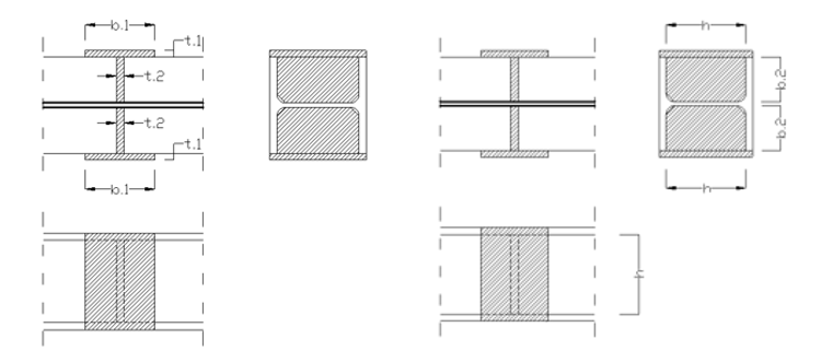
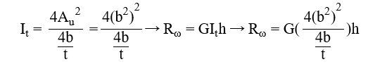
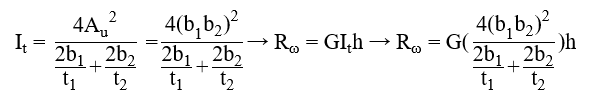
Box stiffener
The box stiffeners are located near the supports as can be seen in Fig. 8. Table 3. contains the geometric parameters of the box stiffeners.
| Name | Dimension | Value |
|---|---|---|
| Width of the web stiffener | [mm] | 100 |
| Thickness of the battens | [mm] | 100 |
| Total width of the box stiffener | [mm] | 200 |
| Height of the plates | [mm] | 300 |
| Thickness of the plates | [mm] | 10 |
Table 3: geometric parameters of the box stiffeners
7DOF beam model
The same effect in a model using 7DOF beam finite elements can be obtained when discrete warping spring supports are defined at the location of the box stiffeners.
Discrete warping stiffness calculated by hand
gateAfter introducing the Eurocode standards several theses have been published on the now much-discussed phenomenon of lateral-torsional buckling of steel structural elements under pure bending. According to that, researchers are working on the development of such new design methods which can solve the problems of the design formulae given by the EN 1993-1-1. This paper gives a detailed review of the proposals for novel hand calculation procedures for the prediction of LT buckling resistance of beams. Nowadays, the application of structural design softwares in practical engineering becomes more common and widespread. Recognizing this growing interest, the main objective of our research work is the development of a novel, computer-aided design method. In this paper, the details of a general type stability design procedure for the determination of the LT buckling resistance of members under pure bending are introduced. Here, the theoretical basis of the proposed method is clarified, the calculation procedure is detailed and some results for the evaluation of the appropriateness of the method are also presented. Based on the evaluations it can be stated that the new, general type design method is properly accurate and has several advantages on the stability check of beams under bending
Click the button bellow to download and read the full article.
gate