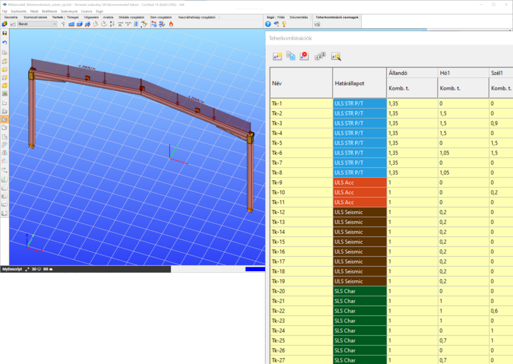
A Consteel lehetőségek széles skáláját kínálja a teherkombinációk szűréséhez, amely határállapot, tehereset, valamint analízis eredmények és kihasználtságok alapján is történhet. Szűrők különböző kombinációinak alkalmazásával a tervezési folyamat tudatosabbá válhat és csökkenhet a számítási idő.
Szűrési lehetőségek
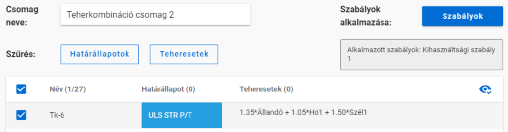
A szűrést a Teherkombináció csomag megadása nevű dialóg on lehet elvégezni.
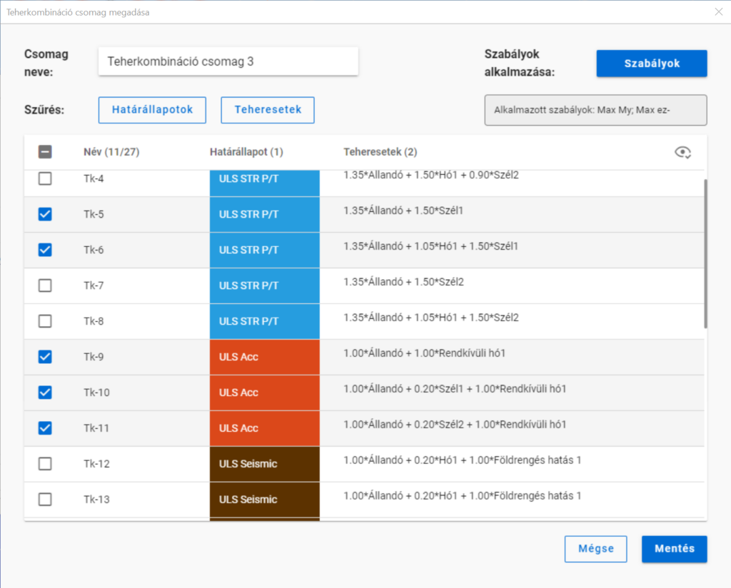
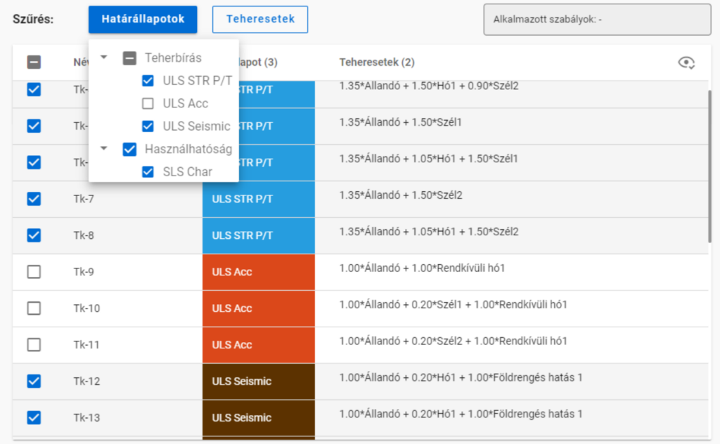
A határállapotok és teheresetek szerinti szűrést az azonos nevű gombok alatt lenyíló jelölőnégyzetekkel lehet végrehajtani.
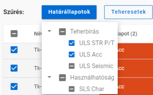
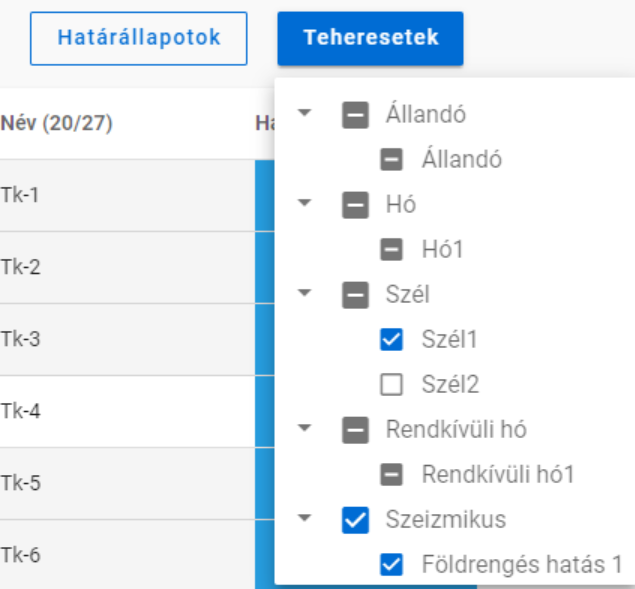
A jelölőnégyzeteknek három állása van. Nem csak kiválasztásra használhatóak, hanem egyben az adott teherkombináció csomag tartalmát is mutatják. Kézzel csak bepipált vagy üres állapotra kapcsolhatók, a köztes állás akkor jelenik meg, ha egyéb szűrőket alkalmazunk.
A határállapotok és teheresetek szerinti szűrést számítási eredmények nélkül is lehet alkalmazni.
A szabályok szerinti szűrés viszont minden esetben analízis vagy tervezési eredményeken alapszik. A különböző típusú szabályokat egyszerre vagy egymás után is lehet alkalmazni, hogy kiválasszuk a kívánt teherkombinációkat.
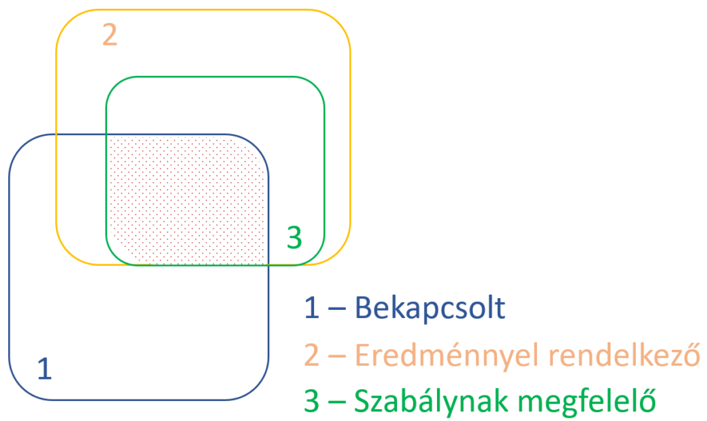
Amikor egy szabályt alkalmazunk, a filter megvizsgál minden teherkombinációt, ami ki volt választva a Teherkombináció csomag megadása ablakban -akár kézzel, akár határállapota vagy a benne lévő tehereset alapján-, minden olyan végeselem pontban, amit a szabály megkíván. Azok a teherkombinációk, amik megfelelnek a szabálynak, kiválasztva maradnak, míg azok, amelyek nem, nem lesznek többé kijelölve.
- Analízis szabály alkalmazásával deformációk vagy igénybevételek alapján választhatunk ki kombinációkat. Az analízis eredményeket a szabály megadásától függően minden végeselem pontban vagy csak az elemvégeken vizsgáljuk (pl. kapcsolatokhoz). Deformációkat csak SLS, míg igénybevételeket csak ULS kombinációkban vizsgálunk.
- Kihajlás szabállyal azok a teherkombinációk választhatók ki, amelyekhez tartozó rugalmas kritikus teherszorzó (első kihajlási sajátérték) kisebb a megadott értéknél.
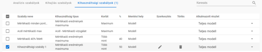
- Kihasználtsági szabállyal a teherkombinációkat a kiválasztott részletmodell minden végeselem pontjában meghatározott kihasználtságok alapján lehet szűrni. Acél elemek esetén a kihasználtságok elérhetők minden szabványos vizsgálatból, mint pl. általános rugalmas szilárdsági ellenállás, tiszta igénybevételi ellenállás, interakciók és globális stabilitásvizsgálat. A filter csak ULS kombinációkra alkalmazható.
Különböző típusú szűrők kombinálása
A háromféle szűrőt lehetséges és érdemes együtt használni, azonban fontos tudni, hogy a szabályok szerinti szűrést csak azokon a kombinációkból válogat, amik ki vannak választva és van hozzájuk megfelelő számítási eredmény.
Vegyünk egy példát!
Egy egyszerű síkbeli keretmodell, amiben 27 teherkombinációt generáltunk többféle határállapotban. Az analízis és szabványos tervezési eredmények rendelkezésre állnak az összes teherkombinációban.
Alkalmazzunk egy kihasználtsági szabályt, amely kiválasztja azokat a teherkombinációkat, ahol a legnagyobb mértékadó kihasználtság 50% felett van.
Ekkor négy teherkombinációt kapunk:
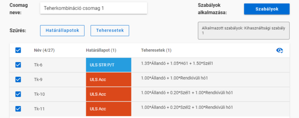
De ha az 50%-os szabály alkalmazása előtt kikapcsoljuk a rendkívüli teherkombinációkat,
akkor a szabály alkamazása után már csak egy kombinációnk marad.
Több szabály alkalmazása
Több szabály együttes alkalmazása esetén a létrejövő teherkombináció-lista azoknak a listáknak az összege lesz, amik a szabály külön-külön való alkalmazása esetén jöttek volna létre.
gateIntroduction
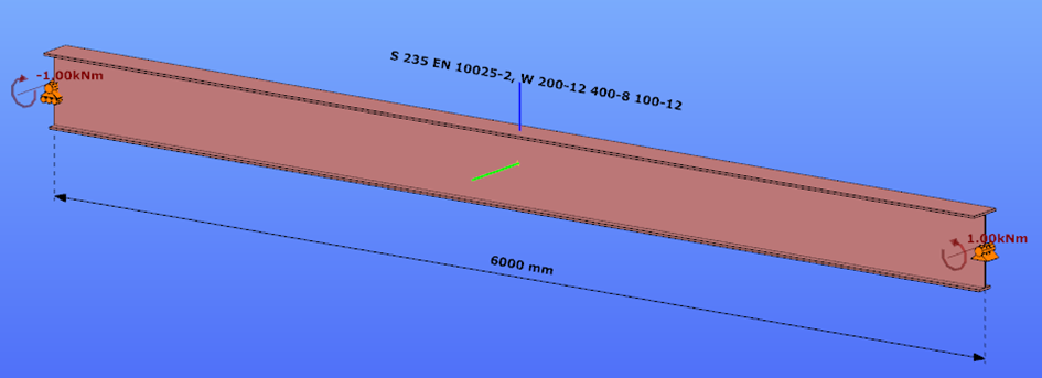
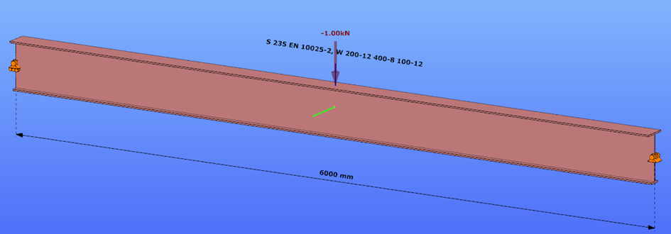
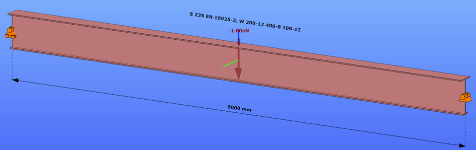
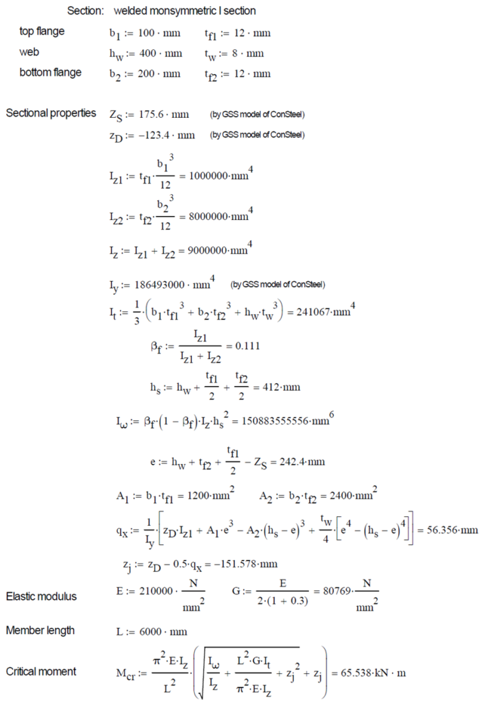
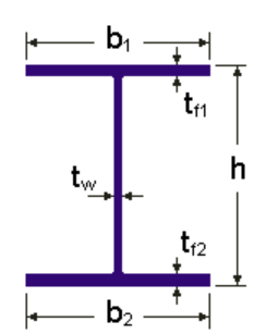
This verification example studies a simple fork supported beam member with welded section (flanges: 200-12 and 100-12; web: 400-8) subjected to bending about major axis. Constant bending moment due to concentrated end moments and triangular moment distribution from concentrated transverse force is examined for both orientations of the I-section. Critical moment and force of the member is calculated by hand and by the Consteel software using both 7 DOF beam finite element model and Superbeam function.
Geometry
Normal orientation – wide flange in compression
Constant bending moment distribution
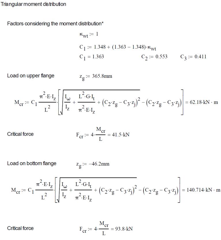
Triangular bending moment distribution – load on upper flange
Triangular bending moment distribution – load on bottom flange
Reverse orientation – narrow flange in compression
Constant bending moment distribution
Triangular bending moment distribution – load on upper flange
Triangular bending moment distribution – load on bottom flange
Calculation by hand
Factors to be used for analitical approximation formulae of elastic critical moment are taken from G. Sedlacek, J. Naumes: Excerpt from the Background Document to EN 1993-1-1 Flexural buckling and lateral buckling on a common basis: Stability assessments according to Eurocode 3 CEN / TC250 / SC3 / N1639E – rev2
Normal orientation – wide flange in compression
Constant bending moment distribution
Reverse orientation – narrow flange in compression
Computation by Consteel
Version nr: Consteel 15 build 1722
Normal orientation – wide flange in compression
Constant bending moment distribution
- 7 DOF beam element
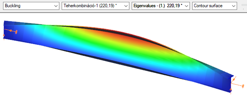
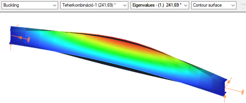
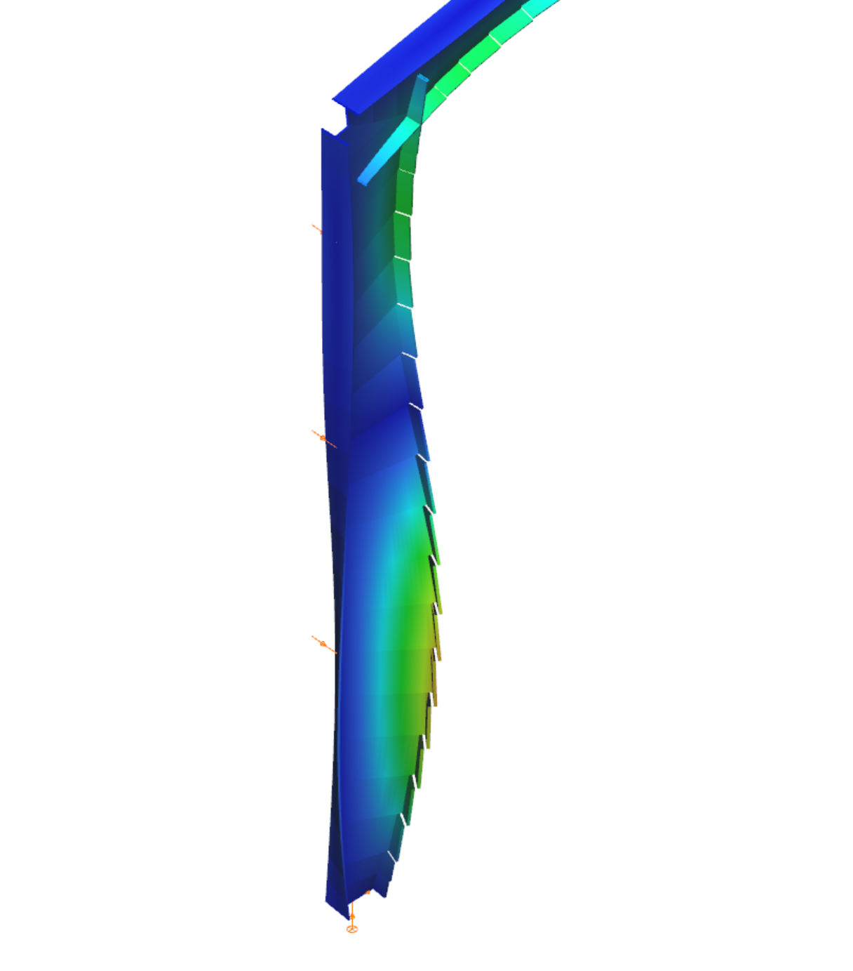
First buckling eigenvalue of the member which was computed by the Consteel software using the 7 DOF beam finite element model (n=25). The eigenshape shows lateral torsional buckling.
Superbeam
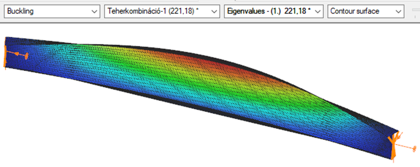
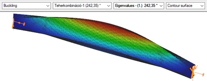
First buckling eigenvalue of the member which was computed by the Consteel software using the Superbeam function (δ=25).
Introduction
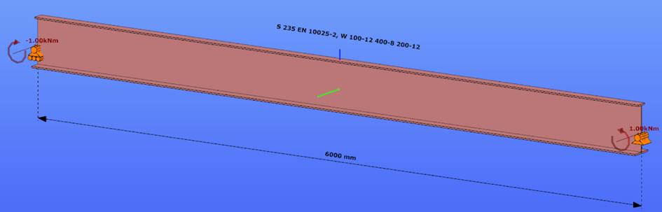
This verification example studies a simple fork supported beam member with welded section (flanges: 200-12; web: 400-8) subjected to bending about major axis. Constant bending moment due to concentrated end moments and triangular moment dsitribution from concentrated transverse force is examined. Critical moment and force of the member is calculated by hand and by the Consteel software using both 7 DOF beam finite element model and Superbeam function.
Geometry
Constant bending moment distribution
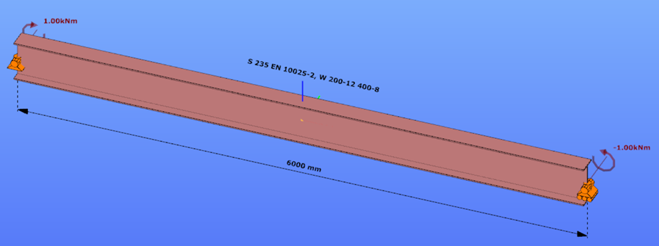
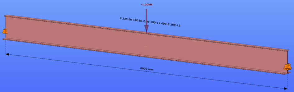
Triangular bending moment distribution – load on upper flange
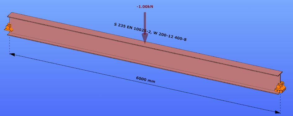
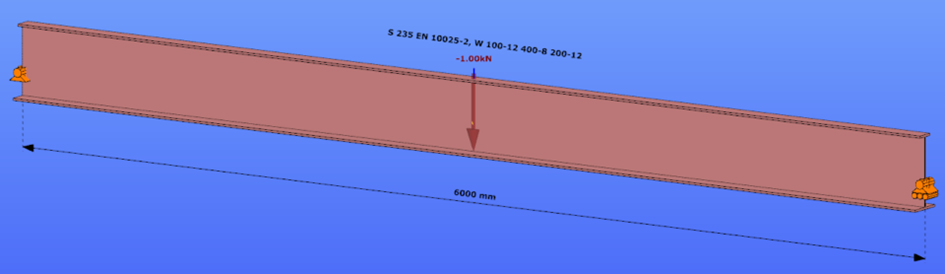
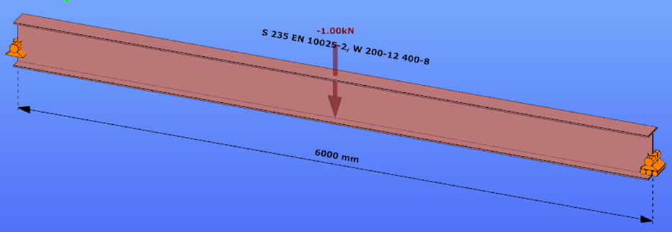
Triangular bending moment distribution – load on bottom flange
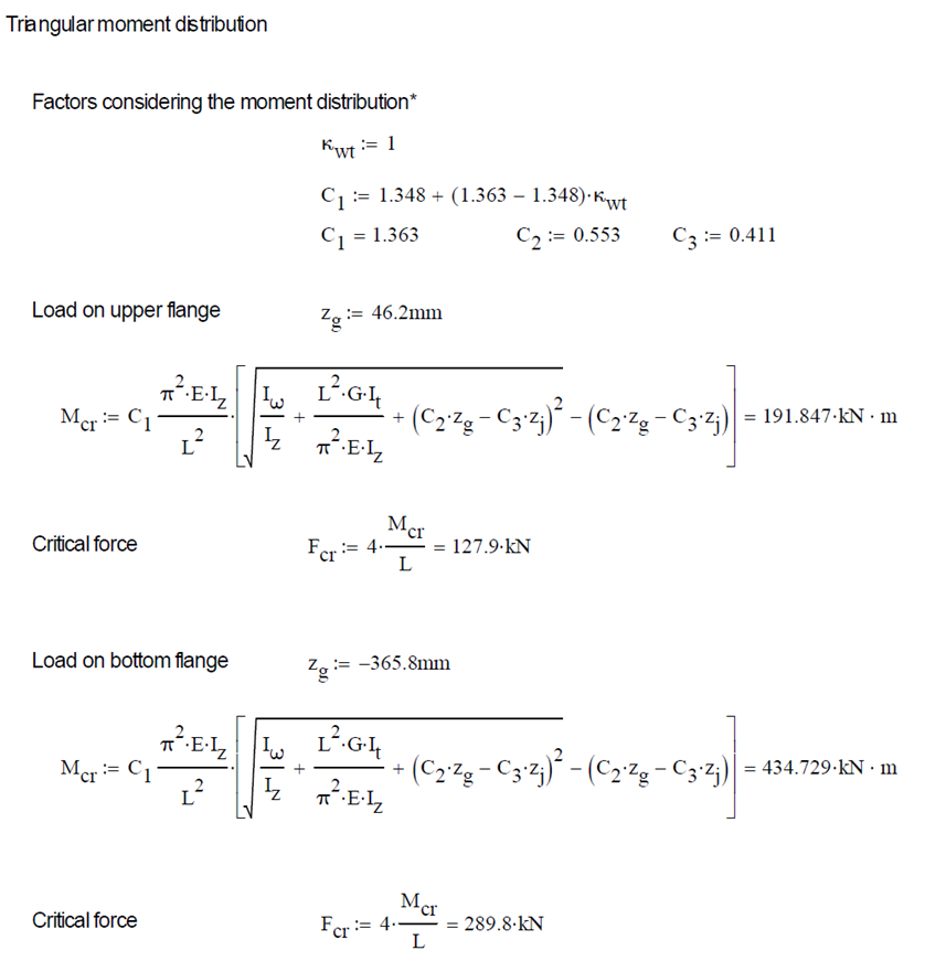
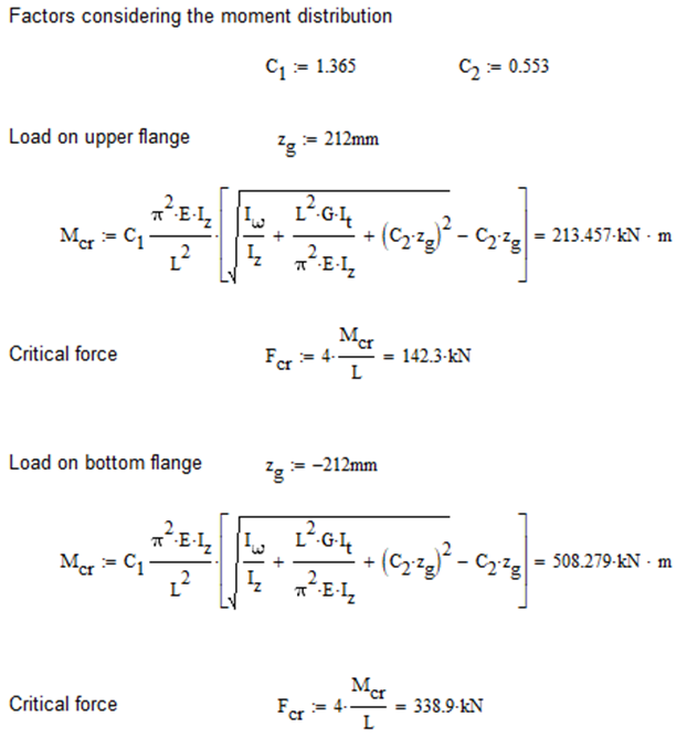
Calculation by hand
Constant bending moment distribution

Triangular bending moment distribution
Computation by Consteel
Version nr: Consteel 15 build 1722
Constant bending moment distribution
7 DOF beam element
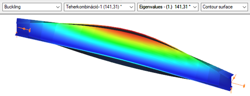
First buckling eigenvalue of the member which was computed by the Consteel software using the 7 DOF beam finite element model (n=16). The eigenshape shows lateral torsional buckling.
Superbeam
First buckling eigenvalue of the member which was computed by the Consteel software using the Superbeam function (δ=25).
Triangular bending moment distribution – load on upper flange
7 DOF beam element
First buckling eigenvalue of the member which was computed by the Consteel software using the 7 DOF beam finite element model (n=16).
Superbeam
First buckling eigenvalue of the member which was computed by the Consteel software using the Superbeam function (δ=25).

Triangular bending moment distribution – load on bottom flange
(tovább…)Introduction
As it is important to have a clear overview of the structural model, the visualization of the analysis results is also essential when it comes to effective design process. From Consteel 15 we use an advanced method for deformation representation which makes it smooth and realistic.
Description
Civil engineering software in general use the traditional beam-type deformation representation where the section is shown on the deformation of the reference line. There are some consequences of this representation mode that can be disturbing for the users. The best example is an eccentric support, where the deformed shape is visualized as if the supported point would’ve moved. The reference line indeed moved but the supported point not – the representation can not show that.
With Consteel’s advanced deformation representation not only the position of the reference line points are calculated and the section is only shown automatically, but the positions of all the decorated points of the section are calculated during a post-process and so it is possible to represent the real deformations. As a consequence it is also visible that the supported points stay in position.
Perfect the understanding of your structure with advanced buckling sensitivity results illustrated on proper mode shape and colored internal force diagrams.
gateCivil engineering software in general use the traditional beam-type deformation representation where the section is shown on the deformation of the reference line. In Consteel 15 we use an advanced method for deformation representation which makes it smooth and realistic. The analysis results are the same, but with the improved visualisation the real 3D behavior of the structure can be better seen.
gateGood model and result visualization leads to better understanding and correct interpretation of any data model compared to texts or tables. With the help of Coloring by section feature, you will be able to switch to a new model view where the members get colours from their cross-section type. Watch the feature preview below and learn how to use the Coloring to make your model more perscpicuous.
gateIntroduction of Consteel Superbeam
In general, Consteel uses 7 DOF beam elements for finite element analysis of steel structures which are adequate for most everyday design situations. It is also capable of using shell elements in order to get more precise results in cases where beam finite elements are not sufficient enough. With the new Superbeam function it is now possible to examine structural parts with the accuracy of shell elements but with the ease of using a beam element concerning definition, modification, model handling, etc. In practice, it means that 7DOF beams can be switched to shell elements (and back) at any stage of the design process.
Validation
The validation program aims to verify the full mechanical behavior of the Superbeam switched to and analyzed as shell elements within a structural model composed of 7DOF beam elements. The validation of the analysis of the shell finite elements was done before and it is clear that in the case of correctly set boundary conditions the results are the same as the beam model provided that the local web buckling effect is avoided because it can not be modeled with beam-theory. Therefore the accuracy of the mechanical behavior of the Superbeam basically depends on two major factors:
- 1. the automatic shell modeling and mesh of the Superbeam
- When transforming a beam model in the structural analysis to shell model, several automatic transformations are done with the model objects (loads, supports, connected elements etc.) in order to yield a consistent mechanical model.
- 2. the mechanical consistency of the connections of Superbeam at the boundary to 7DOF nodes
- To satisfy the mechanical consistency at the connecting nodes the Superbeam uses automatically set constraint elements at both ends. They ensure the compatibility of the complete displacement field (translations, rotations, and warping) with the adjacent 7DOF beam finite element node or with the 7DOF point support.
The validation studies prove that the beam analysis model is mechanically equivalent to the shell analysis model within the Superbeam by comparing the results of the two models. It is shown that
- in the case of models where the local plate-like specific behavior is not relevant (thick plates in the cross-secions) the results are the same
- in the case of models where the local plate-like specific behavior is relevant (thin plates in the cross-secions) the results can be different only because of this plate-like behavior (local buckling, cross-section distortion) while the isolated beam-like behavior is the same
Part 1
In this first part of the validation, we examined simply supported beams of welded I-sections with several different profile geometries. The full length of the beams was changed to Superbeam shell and so the consistency of results of both the shell elements and the constraints could be analyzed.
Structural models and analysis
In every case, the beam was first calculated with 7 DOF beam finite elements, after with Superbeam shell elements, and finally also as a full shell model with the same finite element sizes as the Superbeam shell. In full shell models, we applied rigid bodies along the edge of the web.
Linear buckling analysis was executed in order to compare the first buckling eigenvalues.
Our expectation was that the two kinds of shell models would produce very similar results which are by nature somewhat less favorable than the 7 DOF beam results, meaning that alfa critical values should be lower when using shell elements. To be able to compare the results related to global (lateral-torsional) buckling, the effect of local buckling of the web was to be avoided as much as possible so the examples were chosen accordingly.
Geometry
Loading
gateTheoretical background
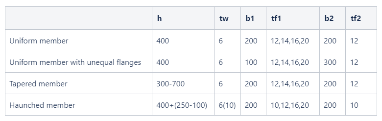
According to the beam-column theory, two types of torsional effects exist.
Saint-Venant torsional component
Some closed thin-walled cross-sections produce only uniform St. Venant torsion if subjected to torsion. For these, only shear stress τt occurs.
The non-uniform torsional component
Open cross-sections might produce also normal stresses as a result of torsion.[1.]
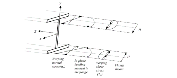
Warping causes in-plane bending moments in the flanges. From the bending moment arise both shear and normal stresses as it can be seen in Fig. 2 above.
Discrete warping restraint
The load-bearing capacity of a thin-walled open section against lateral-torsional buckling can be increased by improving the section’s warping stiffness. This can be done by adding additional stiffeners to the section at the right locations, which will reduce the relative rotation between the flanges due to the torsional stiffness of this stiffener. In Consteel, such stiffener can be added to a Superbeam using the special Stiffener tool. Consteel will automatically create a warping support in the position of the stiffener, the stiffness of which is calculated using the formulas below. Of course, warping support can also be defined manually by specifying the correct stiffness value, calculated with the same formulas (see literature [3]).
The following types of stiffeners can be used:
- Web stiffeners
- T – stiffener
- L – stiffener
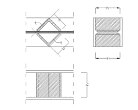
- Box stiffener
- Channel –stiffener
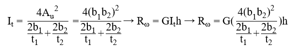
The general formula which can be used to determine the stiffness of the discrete warping restraint is the following:
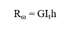
where,
Rω = the stiffness of the discrete warping restraint
G = shear modulus
GIt = the Saint-Venan torsional constant
h = height of the stiffener
Effect of the different stiffener types
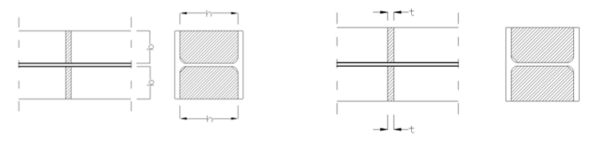
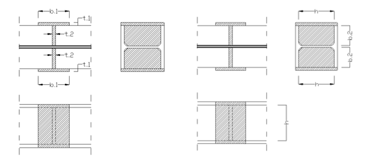
Web stiffener
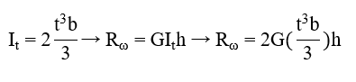
where
b = width of the web stiffener [mm]
t = thickness of the web stiffener [mm]
h = height of the web stiffener [mm]
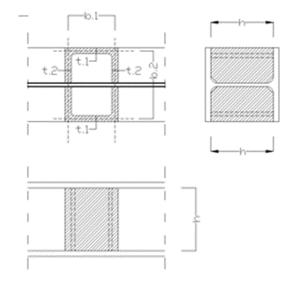
T – stiffener
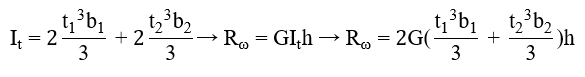
where
b1 = width of the battens [mm]
t1 = thickness of the battens [mm]
b2 = width of the web stiffener [mm]
t2 = thickness of the web stiffener [mm]
h = height of the web stiffener [mm]
L-stiffener
where
b = width of the L-section [mm]
t = thickness of the L-section [mm]
h = height of the L-section [mm]
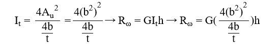
Channel stiffener
where
b1 = width of channel web [mm]
t1 = thickness of channel web [mm]
b2 = width of channel flange [mm]
t2 = thickness of channel flange [mm]
h = height of the web stiffener [mm]
Numerical example
The following example will show the increase of the lateral-torsional buckling resistance of a simple supported structural beam strengthened with a box stiffeners. The effect of such additional plates can be clearly visible when shell finite elements are used.
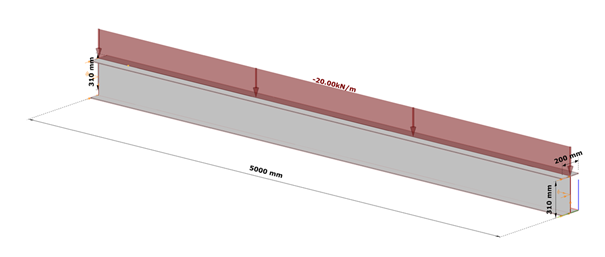
Shell model
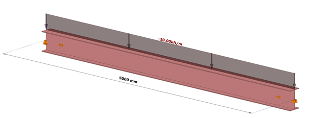
Fig. 7 shows a simple fork supported structural member with welded cross-section modeled with shell finite elements and subjected to a uniform load along the member length acting at the level of the top flange.
Table 1. and Table 2. contain the geometric parameters and material properties of the double symmetric I section. The total length of the beam member is 5000 mm, the eccentricity of the line load is 150 mm in direction z.
| Name | Dimension | Value |
|---|---|---|
| Width of the top Flange | [mm] | 200 |
| Thickness of the top Flange | [mm] | 10 |
| Web height | [mm] | 300 |
| Web thickness | [mm] | 10 |
| Width of the bottom Flange | [mm] | 200 |
| Thickness of the bottom Flange | [mm] | 10 |
Table 1: geometric parameters
| Name | Dimension | Value |
|---|---|---|
| Elastic modulus | [N/mm2] | 200 |
| Poisson ratio | [-] | 10 |
| Yield strength | [N/mm2] | 300 |
Table 2: material properties
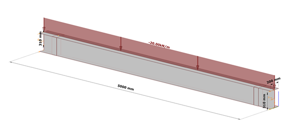
Box stiffener
The box stiffeners are located near the supports as can be seen in Fig. 8. Table 3. contains the geometric parameters of the box stiffeners.
| Name | Dimension | Value |
|---|---|---|
| Width of the web stiffener | [mm] | 100 |
| Thickness of the battens | [mm] | 100 |
| Total width of the box stiffener | [mm] | 200 |
| Height of the plates | [mm] | 300 |
| Thickness of the plates | [mm] | 10 |
Table 3: geometric parameters of the box stiffeners
7DOF beam model
The same effect in a model using 7DOF beam finite elements can be obtained when discrete warping spring supports are defined at the location of the box stiffeners.
Discrete warping stiffness calculated by hand
gateComparison of chosen methods for estimation of critical lateral torsional buckling bending moment of web-tapered I-beams. In this article, the elastic critical bending moments of the web-tapered I-beams calculated by the analytical and numerical solutions developed last years by researchers involved in the topic were compared with own calculations carried out with available common tools. The main goal was to verify the accuracy and convergence of the results provided by different modern methods and different finite bar elements 1D with 7 degrees od freedom at the node (7DOF).
Click the button bellow to download and read the full article. (PL)
gate