Did you know that you could use Consteel to perform dual analysis with 7DOF beam and/or shell elements?
With two advanced features, Superbeam and Convert members to plates, you can choose the approach that best suits your project needs, whether you’re focused on modeling efficiency or detailed analysis.
The Superbeam function offers a smart, adaptive way to handle structural members. It enables you to model with the simplicity of standard 7DOF beam elements while allowing you to switch to a more detailed shell-based analysis for specific members whenever needed.
Once the structure is modeled using beam elements, you can select how each member is analyzed:
- Using the beam model, which applies Consteel’s proven 7DOF beam elements along with its comprehensive design tools.
- Or using a shell model, which is automatically generated for selected members. This shell model includes detailing features such as web cutouts and stiffeners, fully integrated into the global analysis model.
This dual approach is fully adaptive. You can continue modifying your model using beam elements and switch between analysis modes as required, offering both speed and precision within the same workflow.
For a complete overview of how to activate and manage Superbeam functionality, refer to the documentation:
Superbeam – Consteel Manual


When you need complete control over geometry and mesh, or when shell analysis alone is not sufficient, Consteel provides the Convert members to plates function. This tool allows you to manually transform selected members into actual plate elements, enabling detailed modeling from the start.
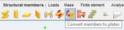
Unlike the automatic conversion used in Superbeam, this method performs a permanent, non-reversible transformation (though undo is available during the session). It supports a wide range of section types, including hot-rolled, cold-formed, and welded profiles.
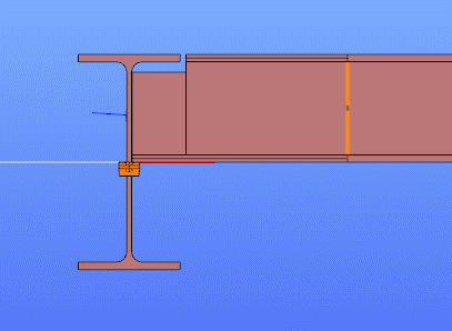
The conversion process preserves and adapts existing connections, eccentricities, loads, and supports. Where needed, rigid bodies and constraint elements are added to maintain structural continuity. These constraints ensure proper transfer of deformations, including warping, between the new plate model and the rest of the structure.
This function is especially useful in cases where precision is critical, such as modeling joints, fabrication-specific details, or complex load interactions.
To learn more, see the full guide here:
Convert Members to Plates – Consteel Manual
Both Superbeam and Convert members to plates serve different purposes, depending on the level of detail and control required in your model:
| Feature | Superbeam | Convert members to plates |
| Workflow | Beam modeling with optional shell analysis | Full plate modeling from the beginning |
| Conversion | Automatic and reversible | Manual and permanent |
| Suitable For | Flexibility in analysis, quick modeling | Full control, high-detail requirements |
| Supported Sections | Welded I and H profiles | Hot-rolled, cold-formed, and welded sections |
| Detailing Support | Cutouts and stiffeners (in shell analysis) | Full geometric detailing, including transitions |
| Design Integration | Integrated with beam-based design tools | Suitable for fabrication-level modeling |
In Superbeam, constraint elements are generated automatically to connect converted shell elements to other members, such as bars. During member-to-shell conversion, these elements link the FE shell nodes to the rest of the model, ensuring accurate deformation transfer.
If the convert members to plate function is applied directly to beam elements, rigid bodies are created at their ends, which is useful for analyzing local behavior but does not transfer warping deformations. If the beam is first converted to a shell and then to plates, hinged rigid edges are placed along the plate boundaries. This arrangement, combined with constraint elements, transfers not only in-plane and out-of-plane deformations but also warping between the shell and the rest of the structure.
Download the example model and try it!
Download modelIf you haven’t tried Consteel yet, request a trial for free!
Try Consteel for freeIntroduction
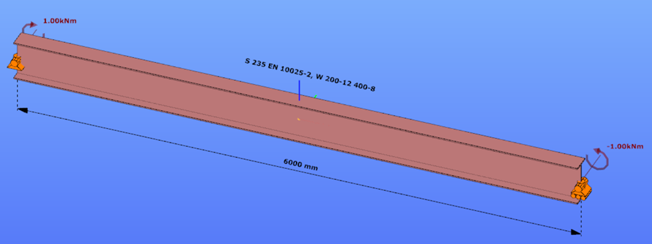
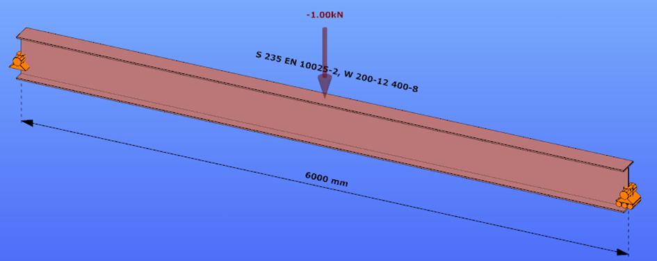
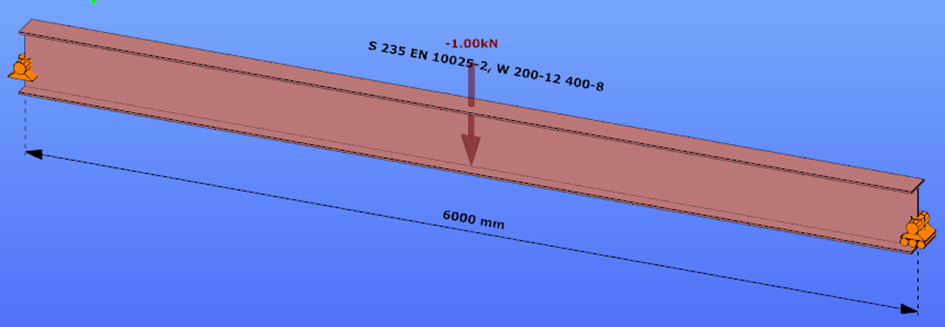
This verification example studies a simple fork supported beam member with welded section (flanges: 200-12; web: 400-8) subjected to bending about major axis. Constant bending moment due to concentrated end moments and triangular moment dsitribution from concentrated transverse force is examined. Critical moment and force of the member is calculated by hand and by the Consteel software using both 7 DOF beam finite element model and Superbeam function.
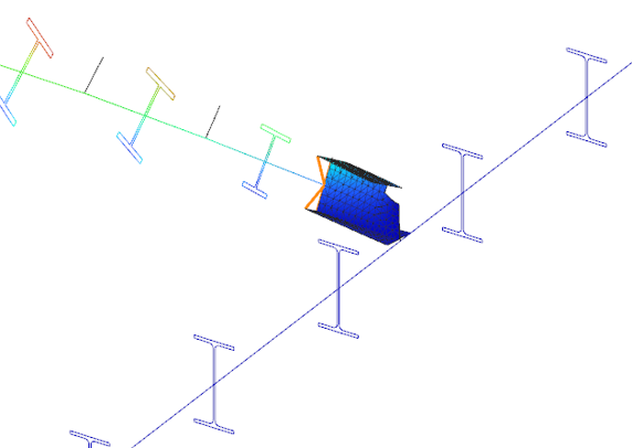
Geometry
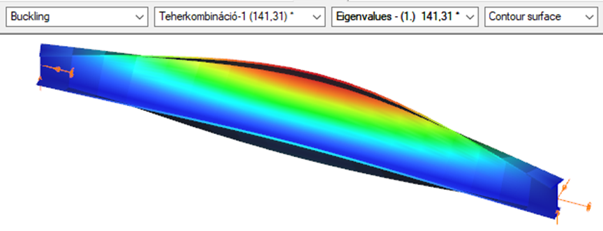
Constant bending moment distribution
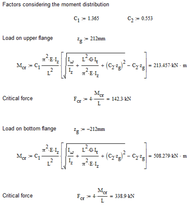
Triangular bending moment distribution – load on upper flange
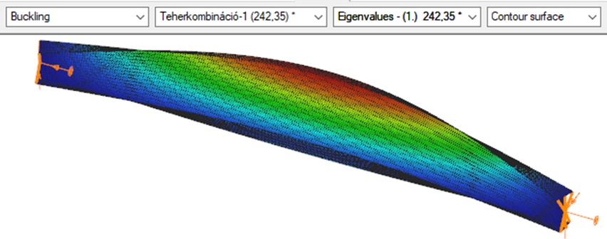
Triangular bending moment distribution – load on bottom flange
Calculation by hand
Constant bending moment distribution

Triangular bending moment distribution
Computation by Consteel
Version nr: Consteel 15 build 1722
Constant bending moment distribution
7 DOF beam element
First buckling eigenvalue of the member which was computed by the Consteel software using the 7 DOF beam finite element model (n=16). The eigenshape shows lateral torsional buckling.
Superbeam
First buckling eigenvalue of the member which was computed by the Consteel software using the Superbeam function (δ=25).
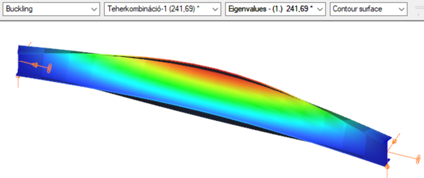
Triangular bending moment distribution – load on upper flange
7 DOF beam element
First buckling eigenvalue of the member which was computed by the Consteel software using the 7 DOF beam finite element model (n=16).
Superbeam
First buckling eigenvalue of the member which was computed by the Consteel software using the Superbeam function (δ=25).

Triangular bending moment distribution – load on bottom flange
(tovább…)Introduction
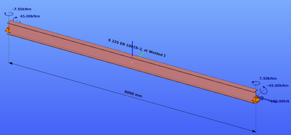
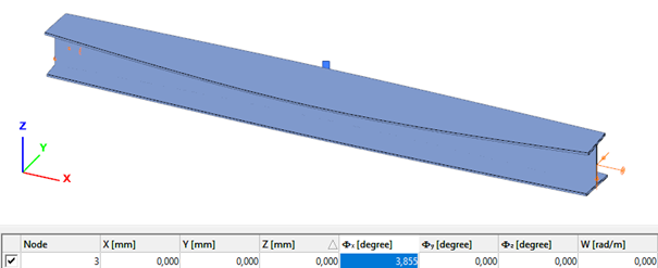
This verification example studies a simple fork supported beam member with welded section equivalent to IPE360 (flanges: 170-12,7; web: 347-8) subjected to biaxial bending due to concentrated end moments and compression due to axial force. Second order deformations of the middle cross-section of the member are calculated by hand and by the ConSteel software using both 7DOF beam and shell finite elements and Superbeam function. In addition to the verification, the difference between modelling with 6DOF and 7DOF elements is demonstrated.
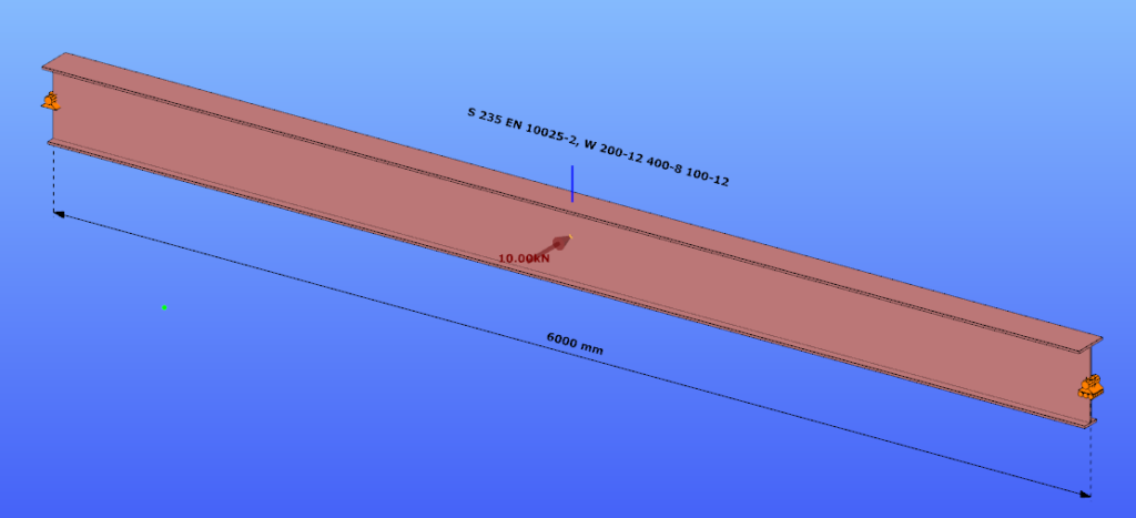
Geometry
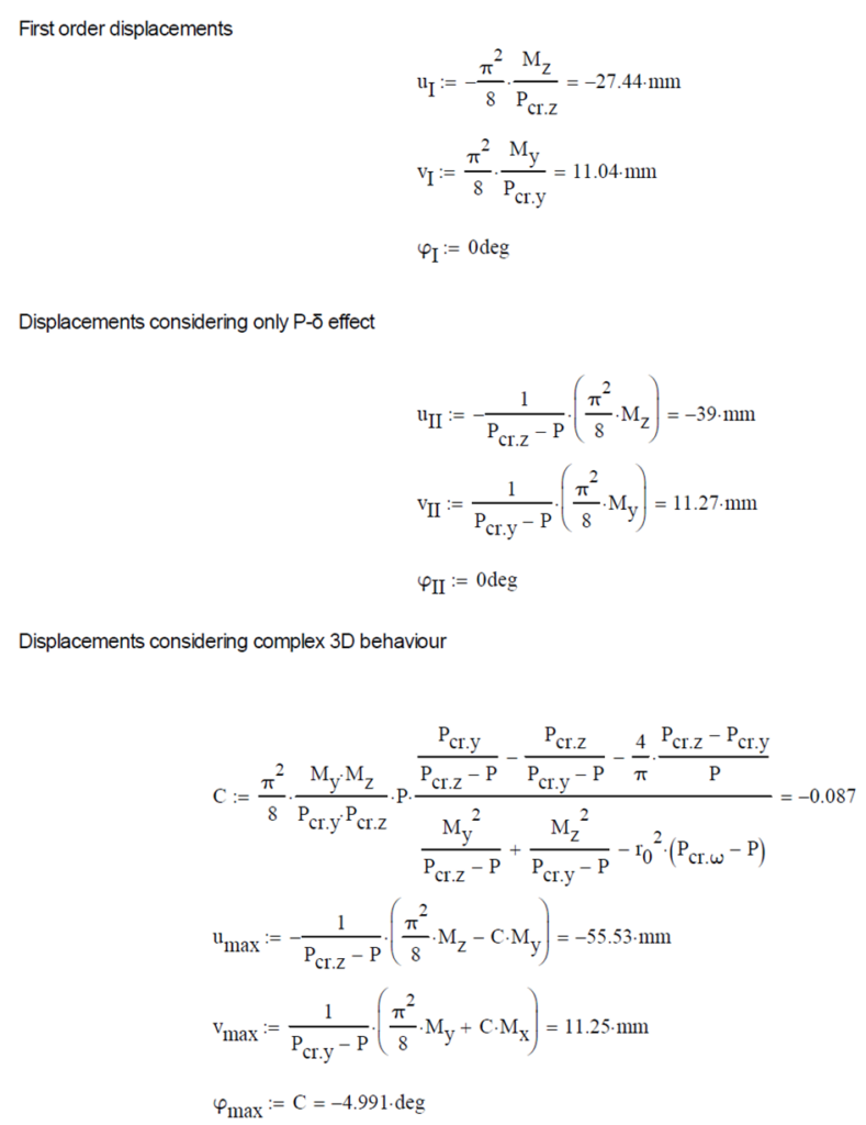
Calculation by hand
The first order and the simple amplified (P-δ) deformations can be analitically calculated by the well known formulas. The calculation of the second order deformations considering true, three-dimensional behaviour of the beam is however so complicated that there are only approximate analitical formulas available for hand calculation. The formula below can be found in Chen, W. and Atsuta, T.: Theory of Beam-Columns, Vol. 2: Space behavior and design, McGRAW-HILL 1977, p. 192

Computation by Consteel
Version nr: Consteel 15 build 1722
First order
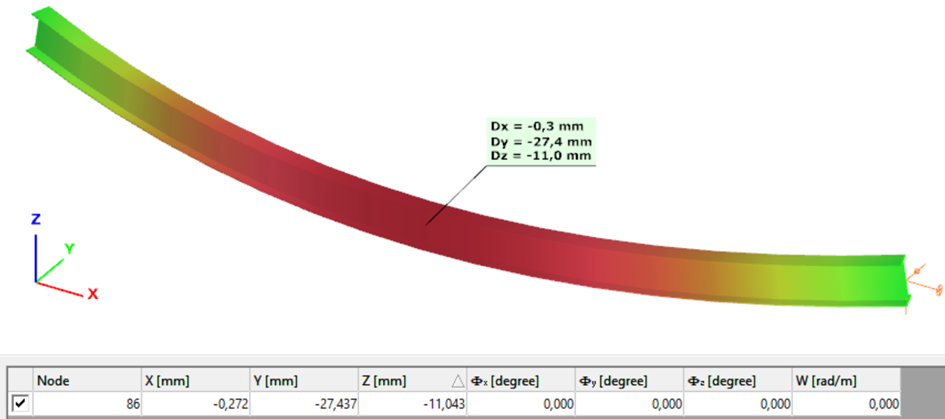
Second order – 6DOF beam element
The second order deformation of the member which was computed by the ConSteel software. It is visible that there is no torsion, only increments of the lateral displacements due to P-δ effect:
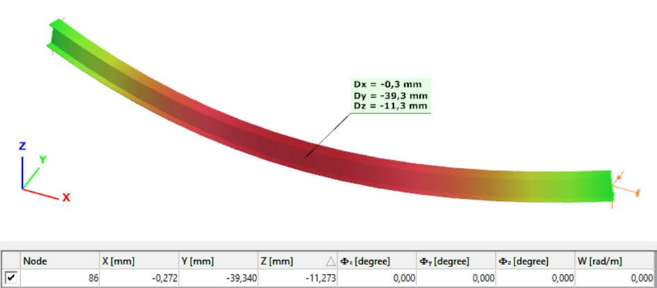
Second order – 7DOF beam element
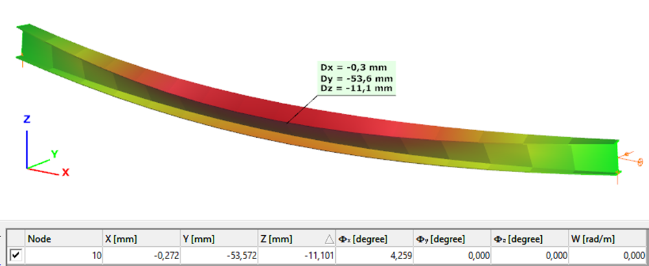
The second order deformation of the member which was computed by the ConSteel software using the 7DOF beam finite element model (n=16). It is visible that there is torsion and further increment in the lateral displacement (Dy):
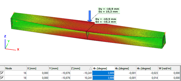
Second order – Shell finite element
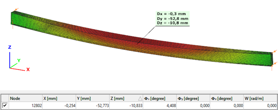
The second order deformation of the member which was computed by the ConSteel software using the shell finite element model (δ=25mm):
Second order – Superbeam
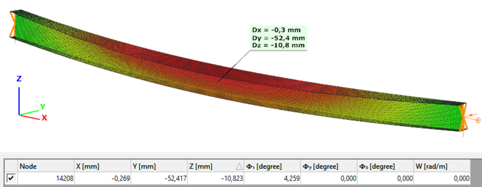
The second order deformation of the member which was computed by the ConSteel software using the Superbeam model (δ=25mm):
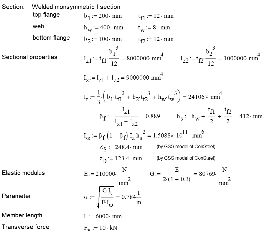
Introduction
Our verification examples are created to be able to compare hand calculation results with Consteel anaysis results with using either 7DOF beam or shell finite elements. This example is a member of mono-symmetric I- section loaded with transverse concentrated load.
Geometry
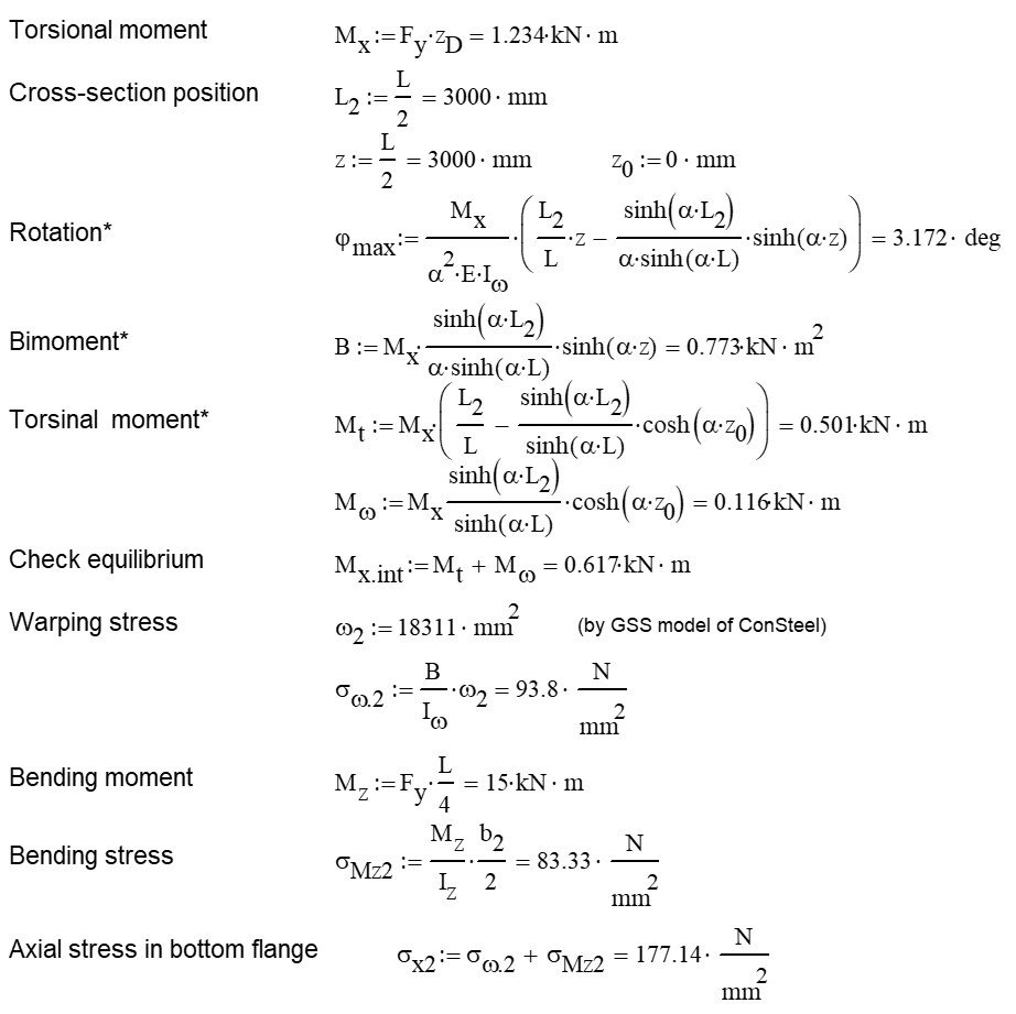
Calculation by hand
Computation by Consteel
Version nr: Consteel 15 build 1488
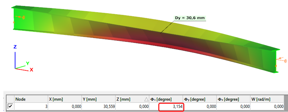
- 7DOF beam element
Deformation of the member with the numerical value of the maximum rotation (self-weight is neglected):
Introduction
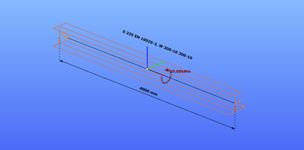
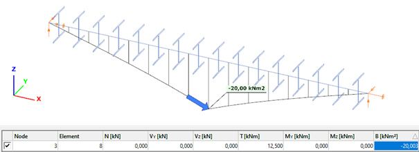
Our verification examples are created to be able to compare hand calculation results with Consteel anaysis results with using either 7DOF beam or shell finite elements including Superbeam function. This example is a member in torsion loaded with concentrated torque.
Geometry
Calculation by hand


Computation by Consteel
Version nr: Consteel 15 build 1488
- 7DOF beam element
Deformation of the member due to concentrated twist moment:
Bimoment of the member due to concentrated twist moment:
Warping normal stress in the middle cross-section:
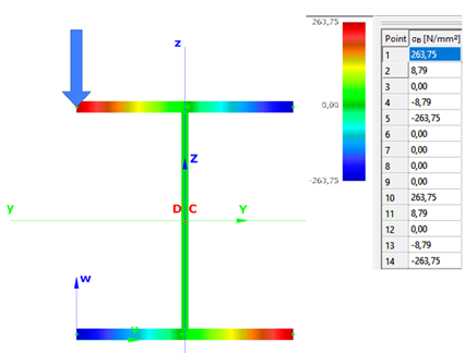
- Shell FE model
Maximum deformation of the middle cross-section:
Introduction
Beam with welded I sections are often executed with slender webs. This is mainly due to the recognition that the main contributors to bending stiffness of a beam are the flanges. The web plate’s main role is to safely keep these flanges away from each other and carry the shear stresses which might be present. Significant weight saving can be achieved with the use of slender webs, but there are some aspects to take care about.
When slender web plates are exposed to longitudinal, uniform normal stresses, above a certain stress level its distribution will no longer remain uniform. A compressed region of a plate distant from its lateral supports may buckle in a direction perpendicular to the acting external normal stresses, causing a subsequent transfer of stresses from the affected region to other neighbouring regions remaining in their unbuckled position.
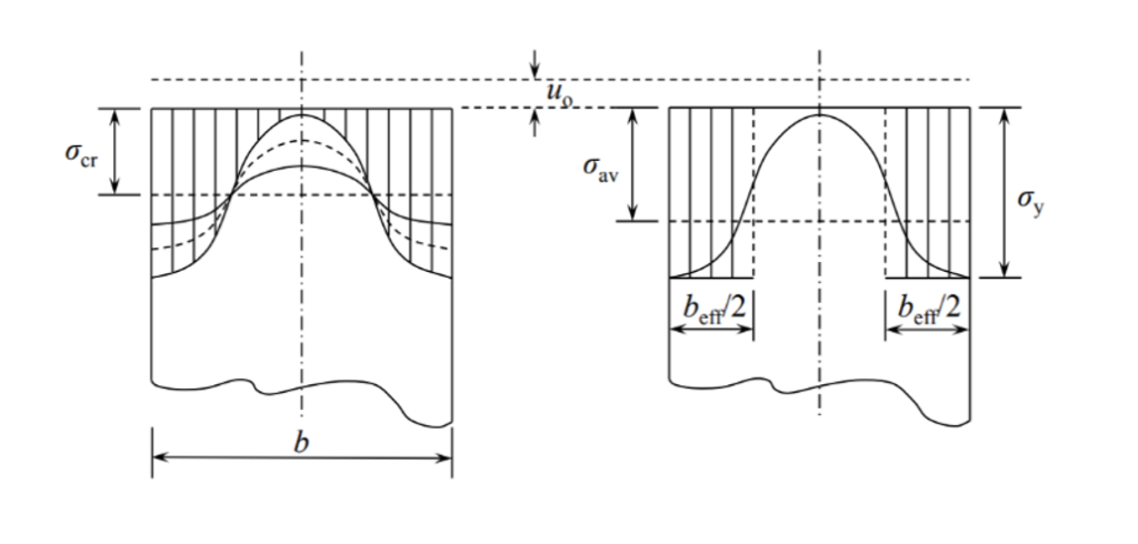
This buckling remains limited to a part of the plate keeping other parts intact and therefore is called as local buckling. Local buckling usually does not result an immediate collapse of the structure, due to possibility of the stresses to redistribute and often even a substantial amount of further load increases are possible.
The tendency of a compressed plate to suffer local buckling is characterized by its slenderness value defined by the following formula
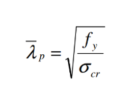
where σcr is the critical stress level above of which the stress redistribution and local buckling starts to appear. A higher critical stress will result in lower slenderness value which indicates that the plate can carry higher compressive stresses without the initiation of local buckling.
Analysis of cross-sections with beam finite elements
The well-known beam finite elements used by usual structural design software do not “see” the internal composition of the cross-section. During structural analysis the sections are represented by certain integrated cross-sections properties assuming the validity of several assumptions including the Bernoulli-Navier Hypothesis and the non-deformability of the cross-section. A local buckling of any of its internal plates would violate these assumptions making hard to create the equivalent cross-sections properties.
In the modern design practice followed by Eurocode the phenomenon of local buckling is handled by the use of effective section properties. Regions subject to possible local buckling of compressed plates of a cross-sections are “eliminated” and the section properties are calculated based on the remaining parts of the cross-sections.
Design verifications use these effective cross-section properties to calculate the resistance of cross-sections exposed compressive forces. When required by Eurocode, the effect of appearance of local buckling can also be reflected in a structural analysis using beam finite elements with the use of effective cross-section properties, instead of the original gross section properties. This is mainly required to prove serviceability criteria.
Analysis of cross-sections with Consteel Superbeam
The Consteel Superbeam function makes possible to confirm directly the presence of local buckling using the same beam element based model, but using a mixed beam and shell finite element modelling and analysis approach. Using the Superbeam tool, complete structural members or parts of them can be alternatively modelled with shell elements and the rest can still be modelled with beam finite elements. Using this technique, the total degrees of freedom of the model can be kept as low as possible. When using Superbeam, the designer has the choice whether to use beam or shell finite elements, as appropriate.
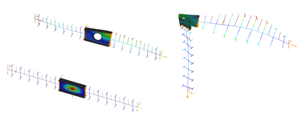
Contrary to beam finite elements, modelling with shell finite elements doesn’t have the previously mentioned limitations. This approach can fully consider the shape and location of the cross-section’s internal components instead of the use of an integrated overall section property. When a linear buckling analysis (LBA) is performed, the critical stress multipliers corresponding to the actual stress distribution can be obtained. Additionally to the load multipliers, the corresponding buckling shapes are also available, giving direct indication on the location, shape and appearance of local buckling within the compressed parts of the cross-section.
The use of effective cross-section concept is very convenient but there might be cases when more insight view is desired. The following example gives an idea where the Superbeam function can be helpful.
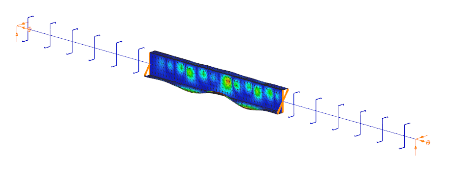
Demonstrative example
Let’s consider a 12 m long simple supported welded beam with the following parameters
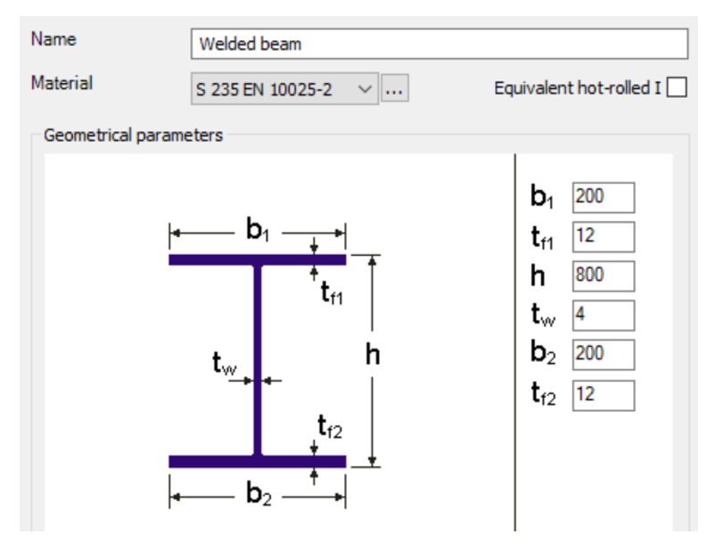
The beam is laterally restrained at third points at the level of its upper flange. The beam is loaded with its self-weight plus a uniformly distributed load of 10 kN/m acting at the level of upper flange.
When the beam is analysed with 7DOF beam finite elements, one can obtain the critical load multiplier of 5.2 of the global buckling mode, which is lateral-torsional buckling (LTB) in this case.
The beam finite element cannot give any visible indication about possible local buckling in compressed plates of the cross-sections.
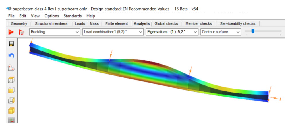
As the maximum bending moment occurs in the middle third of this beam, it seems enough to analyse this part mode deeply with the Superbeam function. An LBA with the mixed beam and shell model gives comparable critical multiplier of 5.22 with some numeric perturbances in the part modelled with shell elements.
gateClick the button bellow to download and read the full article at page 187-195.
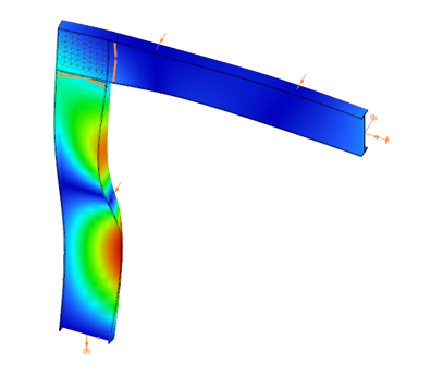
In this paper a numerical study is presented which examines a steel frame with two different finite element programs. Stability failure is more frequent in a lot of cases than strength failure hence it is important to focus on these failure modes: global, in-plane-, out-of-plane -, lateral-torsional- and local buckling. Three models were used with different elements such as shell elements and 7 DOF beam elements. 7 DOF beam elements were used in the first model, shell elements were used in the other two. The first of the shell models gave too much local buckling shapes therefore it was improved with local constraints and that is the third model where global buckling shapes can be examined. There are three different procedures to calculate the resistance: (i) the general method, (ii) the method of the reduction factors, and (iii) the simulation. The analysis results of the different programs and design methods were compared to each other and to the manual calculation based on the Eurocode 3 standards.
gate