A Consteel Diplomapályázat minden évben meghirdetésre kerül, amelyre várjuk minden olyan végzett hallgató jelentkezését, aki a Consteel segítségével készítette el diplomamunkáját. A 2020/2021-es tanév Consteel Diplomapályázat kiírását ide kattintva találod.
A 2020-ban meghirdetett Consteel Diplomapályázat nyertesét, Arendt Esztert kértük fel, hogy írjon blogunkra egy beszámolót Msc diplomamunkájáról, s röviden mi is kérdeztük őt a projektről, amelybe bekapcsolódott.
Szabadformájú rácsos acél felületszerkezet paraméteres vizsgálata
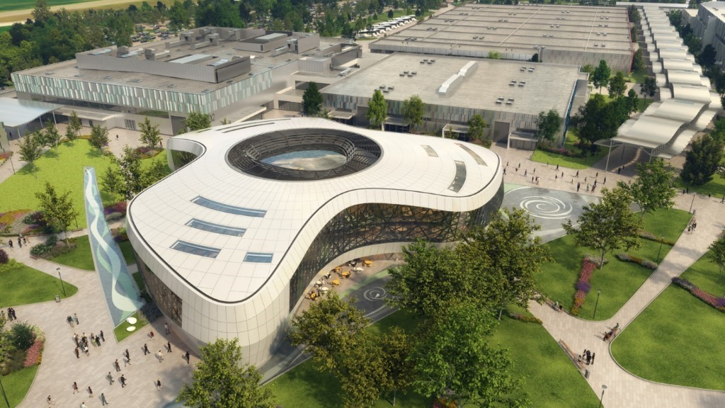
Diplomamunkámban a Hungexpo új fogadó épületének tetőszerkezetét terveztem át.
A propeller alakú épület befoglaló mérete kb. 72,0 x 67,0 m. Az épület homlokzata acélból készülő rácsos szerkezet, az acél tetőszerkezet a homlokzati tartószerkezettel összefüggő acél térrács.
A tetőt a szélein a homlokzaton lévő acél térrács, míg középen egy monolit vasbeton gyűrű támasztja meg. A középen lévő üvegszerkezet, illetve járható gépészeti udvar is a monolit vasbeton gyűrűre terhel, így a középső rész a tető többi részének teherviselését nem befolyásolja. A tetőszerkezet egy gömbfelületre illeszkedik.
Mivel ez egy szabad formájú szerkezet, így a tervezéséhez Grasshoppert, egy erős matematikai hátterű szoftvert használtam, melynek segítségével bonyolultabb geometriai formákat is könnyedén létre lehet hozni. Emellett nagy előnye, hogy parametrikus tervezést tesz lehetővé, így sokféle kialakítást, lehetőséget lehet vizsgálni vele.
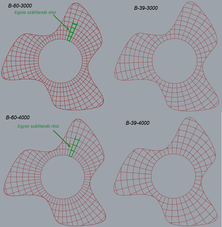
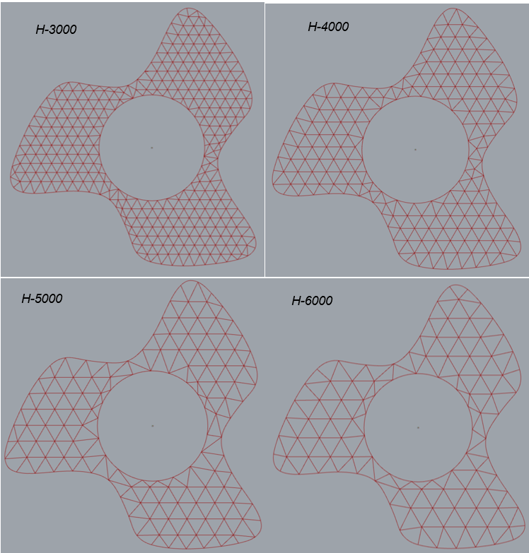
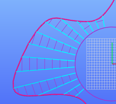
Diplomamunkámban 2 féle rácsozat kialakítást vizsgáltam, az egyik egy bordás, másik egy háromszög hálózat volt. Mindkét hálózathoz 4-4 altípus tartozott, amelyek az osztásközeikben tértek el egymástól. A különböző altípusokat gyárthatóság, szerelhetőség és szállíthatósági szempontok szerint alakítottam ki. A koncepcionális tervezés során ezt a 8 kialakítást vizsgáltam és értékeltem és ezekből kerestem a legkedvezőbb megoldást.
A számításokat Consteelban végeztem, melynek közvetlen összeköttetése van a Grasshopperrel a Pangolin plugin által, így fel tudtam építeni a statikai modellt teljesen parametrikusan.
A geometria, amelyet kialakítottam Grasshopperben térgörbéken alapszik, viszont a tervező szoftverek a Grasshoppernél kisebb palettával rendelkeznek a geometriai kialakítást illetően, így a modellt úgy alakítottam át, hogy a ConSteel tudja kezelni az elemeket.
A koncepcionális tervezésnél a cél az volt, hogy olyan modellt építsek, amely gyorsan és könnyen vizsgálható és összehasonlítható, így egy-egy ULS és SLS maximális teherkombinációt alkalmaztam csak. A parametrikus modell és a Pangolin segítségével létre tudtam úgy hozni a modelleket, hogy a különböző paramétereket változtatva automatikusan változott a Consteel modellem is, így könnyen vizsgálható volt többféle opció is.Mind a háromszög kialakításnál, mind a bordás kialakításnál megfigyelhető volt, hogy bizonyos osztásközig ki voltak használva a szelvények, de túl nagy osztásközöknél a lehajlás lett a domináns, így a szerkezet már anyagfelhasználás szempontjából nem volt gazdaságos.
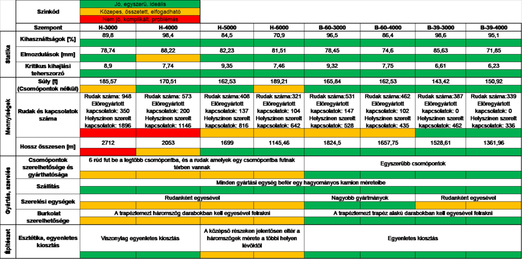
A legkedvezőbb kialakítást egy döntéstámogató opciós mátrix segítségével választottam ki, aminek nagy előnye, hogy a különböző kialakítások szemléletesen összehasonlíthatók több szempont mentén. Az értékelést színkódokkal végeztem. A döntéstámogató opciós mátrix szempontrendszere a következő volt:
Statika
- Maximális kihasználtságok
- Elmozdulások
- Kritikus kihajlási teherszorzó
Mennyiségek
- Súly
- Rudak és kapcsolatok száma
- Hossz összesen
Gyártás és szerelés
- Csomópontok szerelhetősége és gyárthatósága
- Szállítás
- Szerelési egységek
- Burkolat szerelhetősége
Építészet
- Esztétika
Az egyes szempontokat színkódolással értékeltem
- Zöld – jó, egyszerű, ideális
- Narancssárga – közepes, összetett, elfogadható
- Piros – Nem jó, komplikált, problémás
Az értékelés alapján a bordás kialakítások állták meg jobban a helyüket, így az egyik bordás kialakítást vittem tovább a részletes számításokhoz.
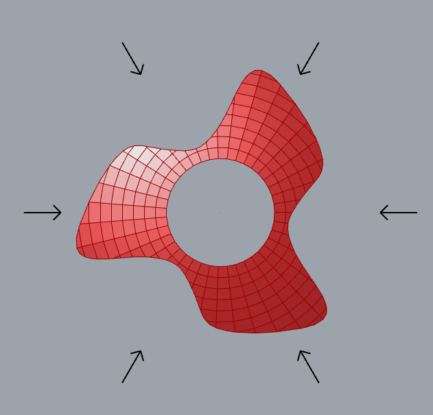
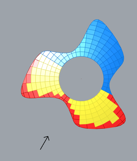
A részletes számítás során a terheket már pontosabban, teherkombinációkkal együtt működtettem a szerkezeten. A legtöbb teher a teljes tetőn felületi teherként működött, a szél viszont különböző zónákban különböző nagyságú volt. Itt mutatkozott szintén nagy előnye a parametrikus modellnek, mivel szabadformájú szerkezet lévén 6 különböző irányból működtettem a szélterhet, a szél zónáit pedig parametrikusan határoztam meg, így a szél irányát változtatva a zónák szintén változtak, így nem kellett egyesével definiálnom a teherpanelekre a különböző terheket.
A részletes számítás során a csomópontok kialakításával és statikájával is foglalkoztam, melyhez a számításokat kézzel, illetve csJointtal végeztem. Számomra tanulságos volt látni, hogy milyen nagy mértékben visszahatottak a csomópontok a főstatikára. Már a koncepcionális tervezésnél a rúdváz megválasztásánál és rúdvég folytonosságok definiálásánál fontos átgondolni, hogy kialakíthatók-e olyan csomópontok, amelyek biztosítják a megfelelő erőátadást.
Összességében nagyon sokat tanultam a diplomamunkám során a tervezési folyamatokról, illetve a parametrikus tervezésről. Azt gondolom a jövőben egyre nagyobb hangsúlyt fog kapni a parametrikus tervezés, így mindenképp érdemes foglalkozni ezzel a témával.
A téma kapcsán beszélgettünk a szerzővel, Arendt Eszter szerkezettervező mérnökkel a projekten szerzett tapasztalatairól.
Interjú
Consteel: Először is gratulálunk mind a diplomádhoz, mind a CS diplomapályázathoz! Hogyan döntöttél úgy, hogy ez lesz a témád? Egy ismert projektről van szó, amelynek a szerkezetén alapul a munkád, hogyan, mikor kapcsolódtál be?
Eszter: A parametrikus tervezéssel az egyetemen egy vendég előadó óráján találkoztam először és már akkor elhatároztam, hogy ebben a témában szeretném írni a diplomamunkámat. Szerencsém volt, hogy a bim.GROUP-nál volt is olyan projekt, ami paraméteres volt és be tudtam kapcsolódni, így adta magát, hogy a diplomamunkámnak is a Hungexpo fogadóépülete legyen a témája. Körülbelül a projekt felénél kapcsolódtam be, és egészen a végéig részt is vettem benne.
Consteel: Milyen szereped volt a projekten? Mit lehet róla tudni?
Eszter: Én leginkább a másodlagos szerkezetekkel foglalkoztam. A burkolatot egy „házikó” alakú hajlított profil fogadta, ami mindenhol követte az épület vonalát, így ezek egyedi profilok voltak. Ennek a statikájával és szerkesztésével foglalkoztam a legtöbbet. Ezenkívül besegítettem, ahol kellett csomóponti számításokba, illetve a tetőn az üvegkupola tervezésébe.
Consteel: Hogy képzelje el egy diák, milyen munkatársként egy ilyen projektben részt venni?
Eszter: Az biztos, hogy kihívásokkal teli. Kezdő mérnökként azt hiszem, hogy minden projekten még nagyon sokat lehet tanulni, de egy ilyen összetett projekten aztán ez kifejezetten igaz.
Consteel: Mi volt az, ami legjobban tetszett a projektben?
Eszter: Szerettem a projektben, hogy egyedi, ezáltal egyáltalán nem volt unalmas, illetve én nagyon élveztem az egész parametrikus tervezést.
Consteel: Mit tartottál/tartasz akár a te feladatod – akár a projekt kapcsán legnagyobb kihívásnak a szerkezettervezésben?
Eszter: Az időt. Az építőipar nagyon fel van gyorsulva, sokszor nagyon szorosak a határidők. Nehéz így igazán jó munkát kiadni a kezünk közül. Azt gondolom kezdő mérnökként ez még inkább kihívás, hiszen nincs sok év tapasztalatunk, így minden új feladat egyben egy tanulás is.
Consteel: Milyen funkcióit használtad leginkább a Consteel-nek? Hol segítette legjobban a munkád?
Eszter: A főstatikai számításokat mind Consteel-ben végeztem. Már a koncepcionális tervezésnél nagyon hasznos volt, hogy egyszerű modellekkel össze tudtam hasonlítani a különböző kialakításokat. Szeretem, hogy a csomóponti számításokhoz az igénybevételeket könnyen és átláthatóan meg lehet kapni. Illetve a csomóponti számításokhoz a csJoint-ot használtam.
Consteel: Mi volt a legnagyobb előnye a Grasshopper-Consteel integrációnak? Hogy lehetett volna megoldani a feladatot enélkül?
Eszter: Szerintem nagyon sok előnye van, de talán 3 dolgot emelnék ki:
- nem kell kézzel elhelyezni a terheket
- a módosítások nagyon egyszerűen, és gyorsan lekövethetők
- sok kialakítást lehet vizsgálni, így a koncepcionális tervezést segíti
Nem tudom, hogy hogyan oldottam volna meg Pangolin nélkül az átvitelt, talán egy rúdvázat átvittem volna, de akkor is egyesével kell felépíteni a modelleket. A szabadformájú szerkezeteknél szerintem elengedhetetlen a Pangolin, de egyszerűbb feladatoknál is nagyon hasznos tud lenni.
Projekt részletek
Arendt Eszter Msc diplomamunka beszámolója
Konzulensek:
Juhász Márton István – bim.GROUP Kft.
Dr Kovács Nauzika – BME Hidak és Szerkezetek Tanszék
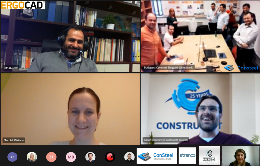
Last week, on the 4th and 5th of February we held our usual yearly meeting with our resellers. It was the 10th time the Consteel Distributors got together – except this was the first time it happened online.
Usually, the distributors visit the Consteel office in Budapest on the annual distributor meetings. But this year there are no journey experiences to share, snacking on the sweet treats that a kind partner usually brings from his homeland for the team, no handshakes or getting together at all. Instead, everyone logged in from their offices, or their own homes to join the meeting. Distributors from Germany, Greece, Poland, Romania and Spain joined us to share sales experiences from 2020 and share and find out more about the plans for Consteel developments in 2021.
On the first morning, each distributor gave a presentation, summarizing last year’s events in a nutshell, and sharing their experiences in 2020 in terms of sales. We could also learn about each other’s experiences of the pandemic, in terms of business. We all had one thing in common: we had almost the same events and circumstances, for shorter or longer periods, such as social distancing, lockdowns, working from home and wearing masks everywhere. After our lunch break, we played a little online game, where everybody could show off their drawing skills on their desktop with a mouse.
The highlight of the day was the announcement of the Consteel Distributor of the Year 2020. The winner of the award this time was Strenco, our distributor in Poland. We warmly congratulate to the winner, Mr Adam Machowiak, for his great work and efforts in 2020, and wish him just as great success in the upcoming year. Sadly, we could not hand him his prize in person, so we had to do a little trick to deliver the winner his trophy. Here you can see a short video of how our „ceremony” turned out.
Our next program was a sales and marketing afternoon when we discussed some new ideas and plans for our sales activities for this new year. The following session was the introduction and preparation for the next morning’s workshop.
Friday started with the workshop: each participant had to use all their creativity. The partners could all share their opinions and brainstorm a bit about future sales possibilities.
This day could not pass without some fun after lunch either – even though we could not have our usual team building this year some more colleagues could play with us from the partner offices, which was nice. Next, it was time to introduce the new developments of Consteel 15 – which we cannot tell more about just yet, but we can assure you that we are looking ahead an exceptional year.
After a short discussion about our communications, came our last event of the distributor meeting: the traditional „Meet the Team” session. The distributor team and the Consteel team turned on their cameras and waved our „Hello” -s to each other
Our 10th Consteel Distributor Meeting turned out just as great as any other. However, we hope that next year we can greet each other face to face again.
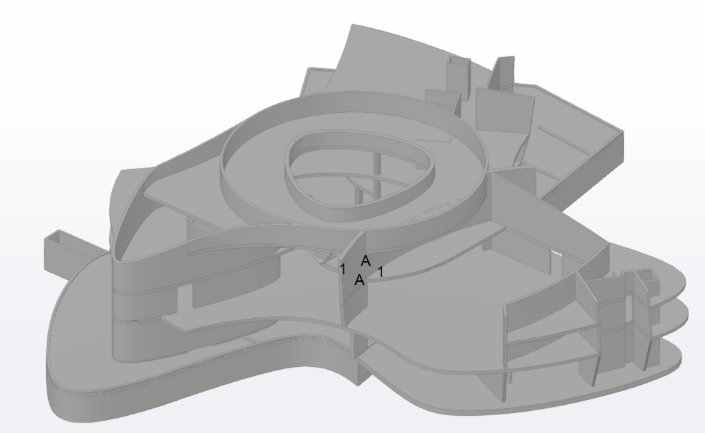
The Hungexpo Budapest Fair is going through a massive revitalization. This project includes the new Arrival Hall Building, an attractive propeller-shaped building. A building with such geometric complexity requires advanced design methods and multi-platform collaboration. In this article, we aim to give an insight into the open BIM environment and parametric design methods used in the design process.
BIM Design Ltd. had various design tasks on the revitalization projects, this article will focus only on the steel design roles of Arrival Hall Building, fabrication and construction optimization, detail and erection design of the steel structure.
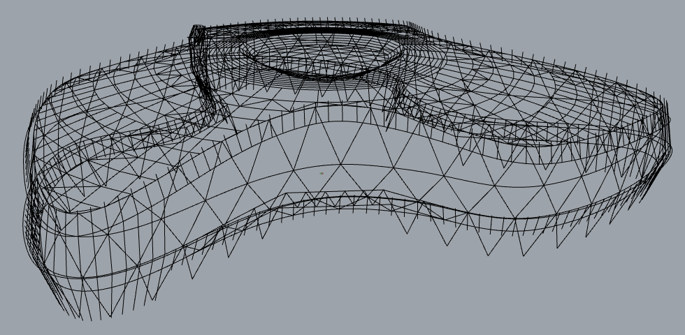
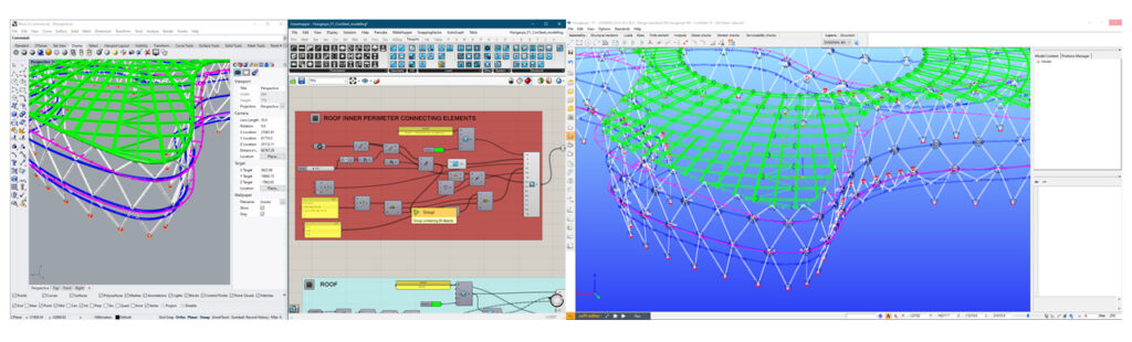
The design workflow is centred Rhino/Grasshopper, the centerline geometry is controlled here. This allows wireframe identical conceptual, structural calculations and shop detailing models. The Consteel is used for design and it is connected to Grasshopper with real-time plugins, the models are generated via visual scripting. All changes in the centerline geometry can be executed to all the models by re-running the scripts. This allows fast, detailed and multi-concept investigations through which we can improve the structure.
GEOMETRIC COMPLEXITY
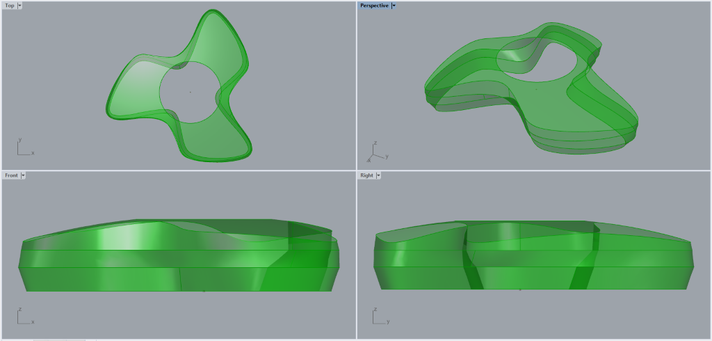
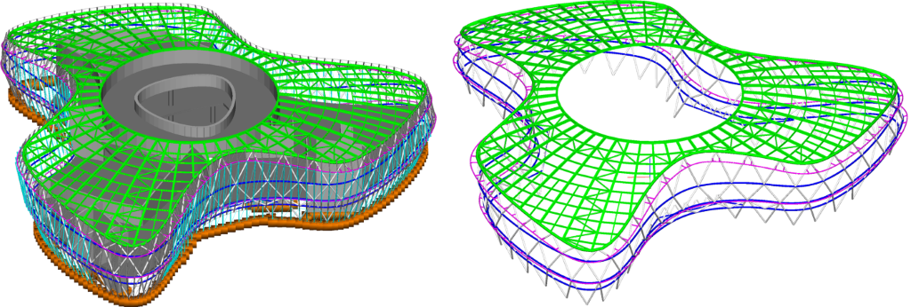
The building envelope is 120° rotationally symmetric, on top view forming 3 identical wings, resulting in a shape of a propeller. The roof surface is laid on a perfect sphere. This sphere has a circular hole in the centre and cut around with a propeller shape perimeter in the outside. The main facade is built up of 3 undulating stripes with distinct edges. These edges are horizontal on the lower levels and spatial on the roof edge, but all are ordinary curves with constantly changing curvature.
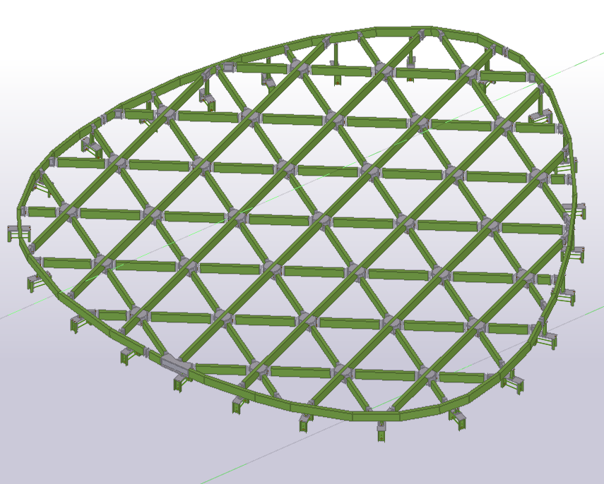
The structure can be divided into 3 parts: the facade structure, the roof structure and the secondary wall purlins. The facade is a multi-level steel truss with roughly 4-5 m wide triangle units. All steel elements are circular hollow sections. The horizontal elements follow the facade surface curvature, the inclined columns (diagonals) are straight. The roof is made of radial and circumferential elements with diagonal bracing. The radial elements are curved among the sphere surface, the circumferential elements in-between are straight beams. The wall purlins stand in a defined vertical plane harmonized with the external cladding layout.
The building’s inner core, the concrete substructure does not keep the rotational symmetry, all 3 wings of the propeller show a different geometry. The load-bearing hierarchy is mixed, in some parts the steel structure supports the perimeter of concrete slabs while in other parts the concrete core supports the steel structure.
A spatial and complex building without proper control of geometry is unlikely to result in identical assemblies. Standardization is a key element in the entire construction process, it’s beneficial to reduce the number of unique assemblies. Data transfer from one software to another, the orientation of elements, local coordinate systems, varying geometric precision setups all add to this inaccuracy.
The building’s peculiarity, the 120° rotationally symmetry stays true for most of the steel structure. This property if used properly can reduce the number of unique assemblies to a third. As a base step, the received centerline geometry was corrected to fulfil this property, resulting in perfectly rotationally symmetric geometry to the fraction of a µm.
SEGMENTATION & STANDARDISATION
All construction elements must be divided into some size to deliver it to the construction site. The facade’s main unit size of the structure is a 4 m triangle, unluckily, it is not the most suitable for well-utilized standard road delivery. Three different segmentation strategy has been investigated using parametric grouping of elements. These concepts cover solutions from the smallest assemblies (joints and beams) to 5 m by 20 m curved spatial trusses. All 3 concepts have been analyzed in collaboration with the contracted manufacturer and the erector, as a result, a mixture of joints and beams, and smaller trusses were selected for detail design with trusses of maximum 2m in height at the entrances.
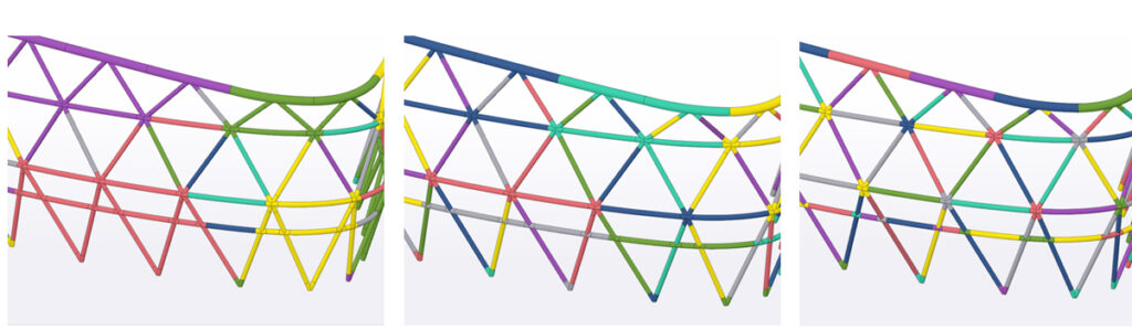
The roof structure has been investigated in the same way, but as a result, all elements were reduced to beams, without forming any trusses.

These parametric investigations require moderate design effort at an early stage of the project but influence significant costs and time in procurement, fabrication, fabrication logistics, delivery, site requirements, lifting and so on. These questions can be better understood and decided through with the aid of these concept models.
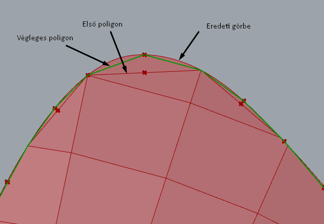
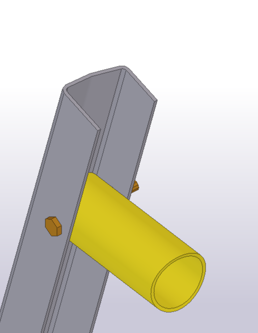
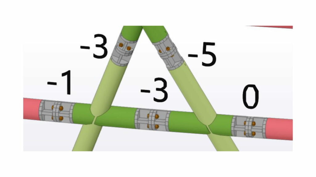
Given the delivery segmentation, another crucial task was to rationalize the ordinary curved girders while maintaining the structure visually appealing. The curves have been divided into straight and planar arc segments. Arced segments are cut perpendicular to the centerline, the resulting angle difference is always cut on the straight segments. This improves the geometric accuracy of manufacturing.
The constructor required to reduce welding on site to a minimum, therefore bolted joints were selected for most of the site connections. The bolted connections were standardized for every cross-section, to allow continuous pre-production of identical parts on the manufacturers assembling and welding robot. As a result, more than 2000 of connection sub-assemblies were manufactured with only 7 distinct splice types.
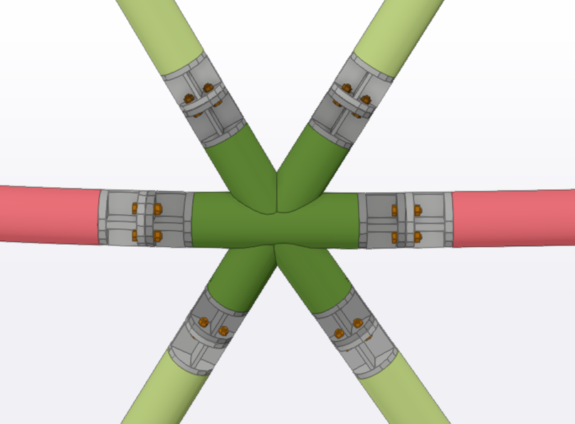
The roof structures standardization originates in the spherical roof geometry, the upper half of the radial beams, circumferential beams on a given circle are identical because centerline geometry is identical, the only condition was to keep these elements’ connection parts identical.
STRUCTURAL CALCULATION & JOINT DESIGN
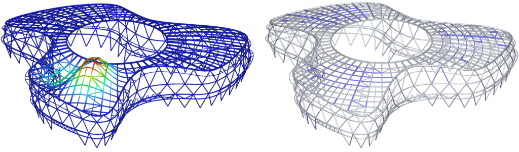
After the model was segmented to fabrication assemblies, the curved elements were rationalized to actual production parts, the next step was to check structural behaviour and section sizes. For this Consteel software was used linked to Grasshopper via the Pangolin plugin. The interface allows a real-time link between the Grasshopper script and the Consteel structural model. Receiving data back from calculation results is in development right now, however, previously created Consteel models can already be referenced in the Grasshopper script. The interface can generate almost all available Consteel objects: geometry, materials, cross-sections, structural elements, supports, loads, load groups.
The components can project the FE model in Rhino viewport similarly as it appears in Consteel, which gives constant feedback of the Grasshopper script writing. The script generates the Consteel model, the structural calculations run inside Consteel with all functionality.
The wind coefficients of the structure were not self-evident since physical wind tunnel test was not available, and the standard does not define coefficients for such shape. As a result for the wall the coefficients we defined to be windward, leeward or sideward zones depending on the angle of the load panel’s normal vector and the wind vector. We divided the angle range two 4 equal segments. The calculated angle is between 315°-45° for the windward zone, 45°-135° and 225°-315° for side walls zone, 135°-225° for the leeward zone. The roof was considered as a double pitched roof, with intense zones on the roof edges. We investigated different 12 wind directions, 30° angles from each other, but later reduced it to 6 major wind directions which are somewhat parallel or perpendicular to the majority of the facade.
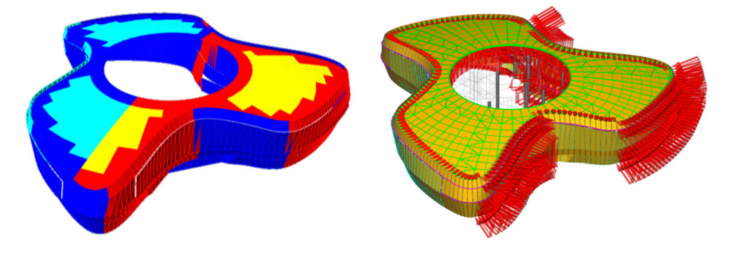
The structural analysis and standard checks are automatically performed in Consteel for the strength, stability, seismic and serviceability limit states using directly the model received from Pangolin, which resulted in a very efficient structural design workflow. All the structural elements were exported to Consteel including the steel and the concrete parts with all supports and loads, the analysis considered the complete model and the design checks considered only the steel members.
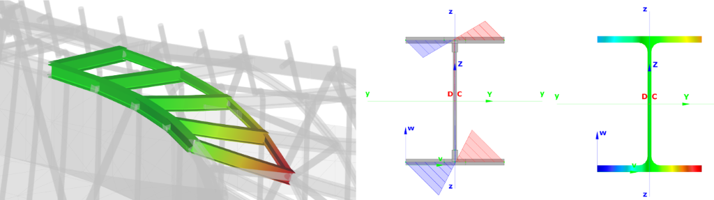
The unique analysis and cross-section models of Consteel allows the automatic calculation and check of all possible internal forces and moments, including the out-of-plane bending and torsion which caused considerable bending and warping stresses along the peripheric beams of the internal circle.
The buckling check of the members for any possible buckling mode was performed by the fully automatic unique method of Consteel based on the “General method” of 6.3.4 in EN1993-1-1 and the refined global linear buckling analysis. In this methodology, the proper member slenderness values are automatically determined by a special buckling sensitivity analysis which selects the critical members for all the relevant buckling modes.
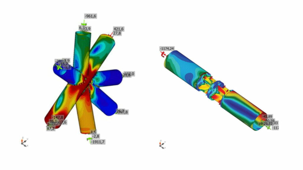
Joint calculations have been performed in IDEA StatiCa. Similar joints were grouped and named systematically already in Grasshopper. These attributes were used for filtering governing forces and geometric extremities for each joint type. The software is linked both to Consteel and Tekla Structures, the interface transfers all necessary geometric, material, and loading data required for the joint design.
3D MODELLING & DETAILING
For steel shop detailing Tekla Structures 2019 was used. Tekla Structures is as well linked to Grasshopper, via the Tekla Live Link plugin. As of today, complete Tekla models can be generated via scripting, including all necessary fabrication attributes: sections, materially, welds, weld preparation, bolts, fabrication phase grouping etc. In our case, the Tekla model was approximately 95% generated via Grasshopper script.
This method allowed deep and iterative investigations to achieve fabrication cost efficiency and best geometric accuracy with moderate extra time and costs in design.
After the final Tekla model generation, 2d drawings and necessary fabrication documentation were prepared inside Tekla.
FABRICATION & ERECTION CONTROL
Fabrication accuracy was a key element. In an early-stage test bending of pipes and “I” beams were performed to assess the accuracy of bent elements. It did not result in bigger discrepancy than the fabrication inaccuracy of the cross-section. String height discrepancy is under ±5 mm, length tolerance is within the normal straight element limits.
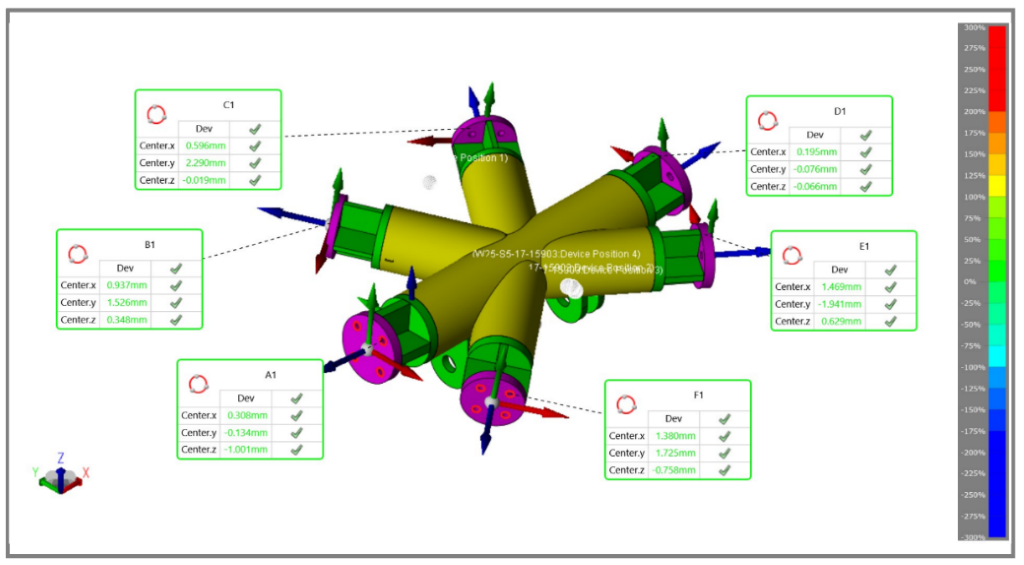
As the segmentation and detail design progressed prototype assemblies were also manufactured to investigate the accuracy of assembling. One of each major assembly types were manufactured and measured with 3d geodesic methods. The measured data was aligned on the design model with the best fit, at the connecting parts the discrepancies were calculated. In the end, the manufacturer decided to use this method not just for checking, but also to adjust assemblies prior to final welding.
The erector has performed a trial assembly of a bigger part of the facade to prove assembling compatibility. The strongest curved part of the facade was selected and assembled in a horizontal position. The structure was measured afterwards, the trial assembly showed no alerting inaccuracy.
The manufacturers’ assembly measurement values were systemized and referenced back to Grasshopper, which allowed pre-evaluation of each unique coherent joints. This data was visualized in 3d on the Tekla BIM model, which is used for predetermination of fitting plates during assembling.
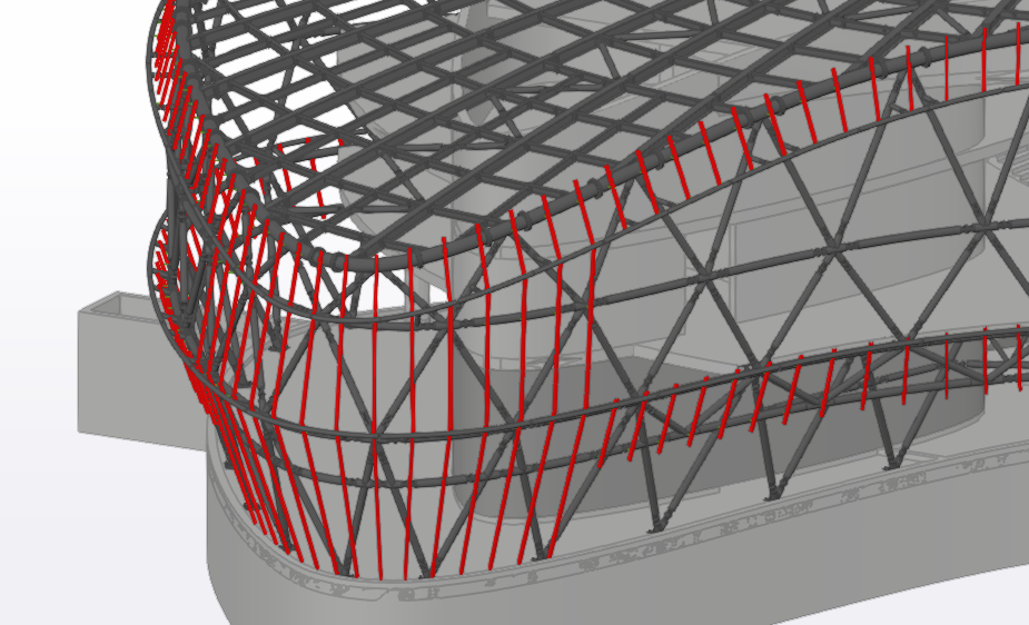
Currently, the site assembly of the steel structure is in progress. It’s planned to perform a full 3d site scan of the assembled steel structure. This measurement data will be used to adjust the secondary purlin system to all manufacturing and erection inaccuracies. Uniquely manufactured cantilevers will be welded on site which will support the cladding system.
PROJECT FACTS
Architect: Finta és Társai Építész Stúdió Ltd.
Structural Designer: Hydrastat Ltd.
Steel Detail Designer: BIM Design Ltd.
Steel Manufacturer: KÉSZ Ipari Gyártó Ltd.
Steel Erector: KÉSZ Metaltech Ltd.
Steel design team: 1 full time lead structural engineer, 2 part-time graduate engineers, 1 full-time modeller, 9 months. 2700m2, 750 tons of steel, 2000 pcs of joints on the facade, 800 pcs wall purlins.