Accurate beam finite element for tapered members
Modeling of tapered elements
Stability calculation of tapered members is always a difficult problem despite its popularity in steel hall construction.
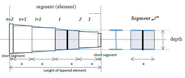
Generally in analysis software for the stability analysis a segmented but uniform beam element method is used where a member with I or H cross section and with variable web depth is divided into n segments and the depth of each segment is taken equal to the real depth measured at the middle of the segment. The lengths of the segments were taken equal, except at both ends where additional shorter segments are added in order the better approximate the real depth of the elements to be modeled. Such model captures correctly the in-plane displacements, but cannot consider accurately the additional torsion coming from the axial stresses due to warping in the flanges which are not parallel with the reference line in case of tapered elements.
This simplification may cause incorrect results in calculating buckling modes involving torsional displacements like flexural-torsional buckling of columns or lateral-torsional buckling of beams especially in cases where the beam flanges have longer unbraced lengths.
Consteel analysis model for tapered members
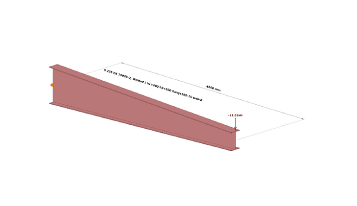
In order to improve the accuracy of the stability analysis of structural models including tapered members Consteel uses a special tapered beam finite element. A basics of this unique finite element have already been published by other researchers however up to now Consteel is the only commercial software which has implemented this finite element for the buckling analysis.
The mentioned problems arising from the non-parallel flanges can be fixed by considering appropriate additional terms in the element stiffness matrix. The final stiffness matrix can be written as a sum of original stiffness matrix and the additional terms:
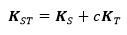
Where KS is for the original stiffness matrix with uniform cross section and KT contains the additional terms valid for doublesymmetric and monosymmetric I and H cross sections.
The additional terms in KT use the following special cross section parameters:
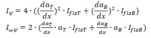
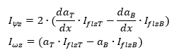
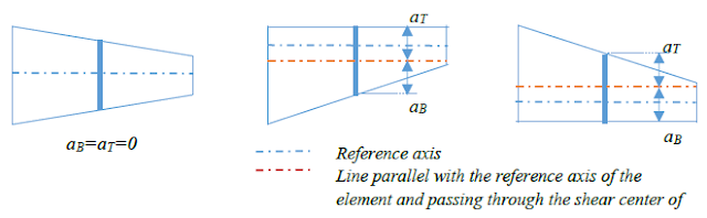
Where IflzT and IflzB are the intertias of the flange related to z axis (parallel to the web), for upper (T) and bottom (B) flanges, respectively, aT and aB is the distance between the centerline of upper and lower flange and the line parallel with the reference axis of the element and passing through the shear center of the middle cross section, as seen on the picture below in case of double symmetric I and H cross section.
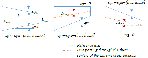
Additionally daT/dx and daB/dx means the angle between the upper and lower flanges and the line parallel with the reference line of the element and passing through the shear center of the middle cross section, respectively. As an approximation these can be expressed as:

where aflT and aflB are the angles between the flanges and the element reference line, ẟshear is the angle between the lines passing through the centers of gravity and shear centers of the extreme cross sections of the elements.
Comparison of results
This part shows some validation examples for the accuracy of the implemented new finite element compared to published numerical results and analysis by shell elements. The examples show the very high accuracy of this element even in the most challenging buckling cases where the segmented uniform beam element method yields some extent of inaccuracy.

Log in to view this content
Online service access and support options are based on subscription plans. Log in to view this content or contact our sales department to upgrade your subscription. If you haven’t tried Consteel yet, try for free and get Pro access to our learning materials for 30 days!
