Did you know that you could use Consteel to consider connection stiffness for global analysis?
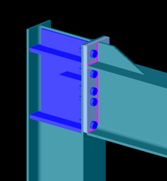
One of Consteel’s unique strengths is its ability to integrate joint modeling and calculation directly into the global analysis.
The Joint module performs all analyses in line with the standard procedures of Eurocode 3 Part 1-8, covering almost the entire scope of the code. This ensures results that are both reliable and fully compliant, across a wide range of connection types such as: Moment connections, Shear connections, Hollow section connections.
Modern structural design increasingly considers the mechanical interaction between the global model and its joints — whether rigid, semi-rigid, or pinned.
If you’d like to dive deeper into how semi-rigid joints influence structural behavior and stiffness classification, check out our detailed article: Semi-rigid joints in modeling of structures.
This integrated approach leads to results that are both more realistic and more economical, but it also requires more sophisticated modeling. Consteel makes this process straightforward:
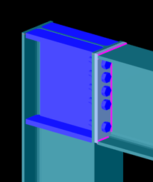
- Joints can be created manually or automatically based on the model geometry.
- The create joint by model function examines member positions and cross-sections, then offers suitable joint types.
- Once defined, the joint can be placed into the global model, and its connection stiffness can be included in the global analysis.
- After placement, the joint is always rechecked against the latest analysis results.
In order to consider the connection stiffness of the placed joint, open the analysis parameters, tick the Include connection stiffness checkbox, and rerun the analysis.
Let’s explore how the behavior of a simple frame changes under different connection assumptions:
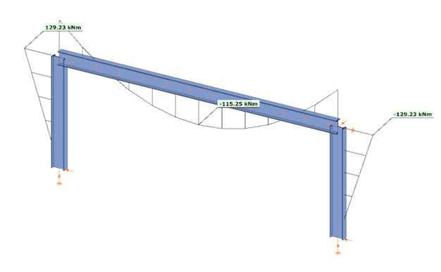
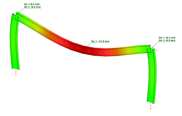
In the first case, where no actual connection stiffness was considered and the members were assumed to have continuous rigid ends, the results showed a bending moment (My) of 129.23 kNm at the column upper end and 115.25 kNm at the beam midspan. The corresponding deflection in the beam’s midspan (z-direction) was –17.4 mm.
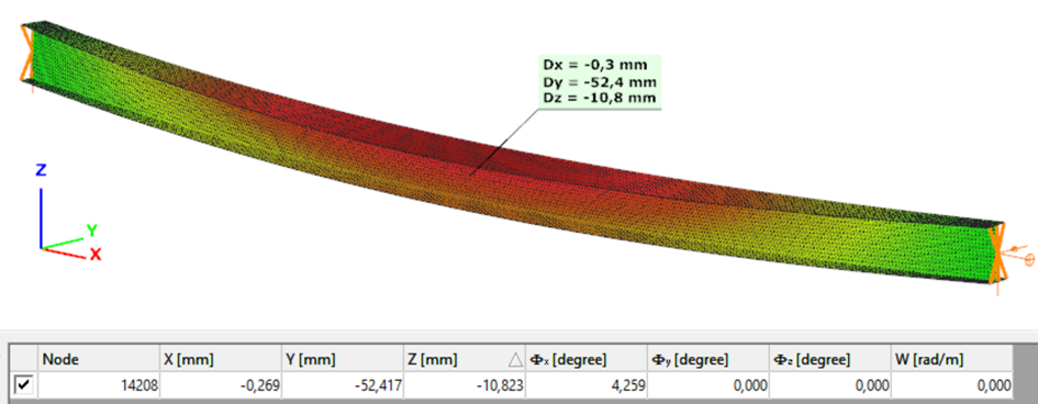
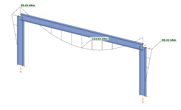
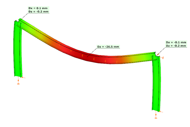
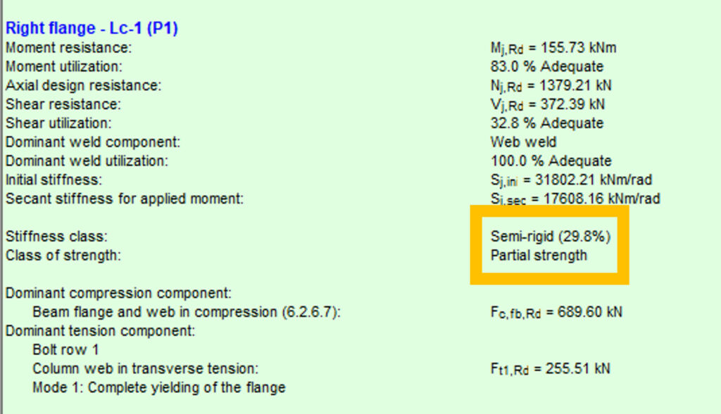
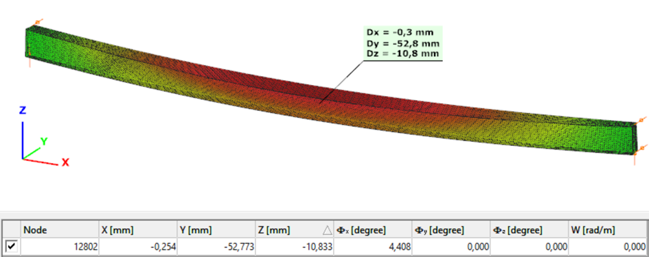
In the second case, the connections were modeled with their actual semi-rigid stiffness of 29.8% and partial strength. Here, the bending moment at the column upper end decreased to 90.45 kNm, while the beam midspan moment increased to 154.03 kNm. The beam midspan deflection reached –26.5 mm, representing an increase of 52% compared to the rigid assumption.
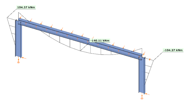
In the third case, with a higher semi-rigid stiffness of 53.6% and partial strength, the results balanced between the two extremes: the column end moment was 104.37 kNm, the beam midspan moment was 140.11 kNm, and the midspan deflection was –23.2 mm. This corresponds to an increase of 33% in deflection compared to the rigid assumption.
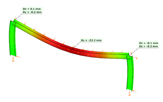

These examples clearly demonstrate how connection stiffness significantly influences global structural behavior. Assuming rigid connections may underestimate beam deflections and distort moment distribution, while considering realistic semi-rigid stiffness, provides a more accurate representation of structural performance.
Download the example model and try it!
Download modelIf you haven’t tried Consteel yet, request a trial for free!
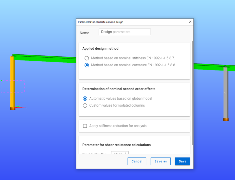
Try Consteel for freeDid you know that you could use Consteel to determine automatically the second order moment effects for slender reinforced concrete columns?
Download the example model and try it!
Download modelIf you haven’t tried Consteel yet, request a trial for free!
Try Consteel for free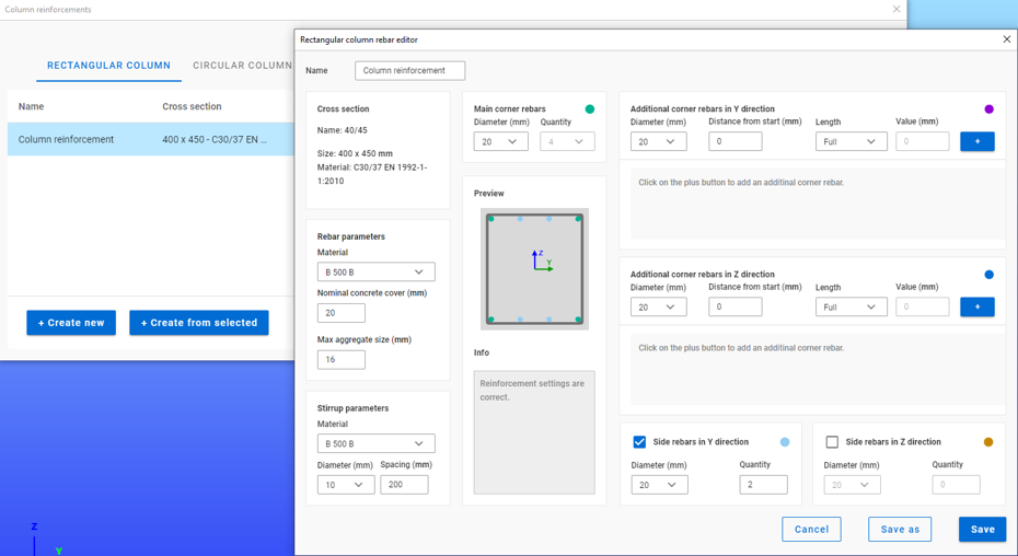
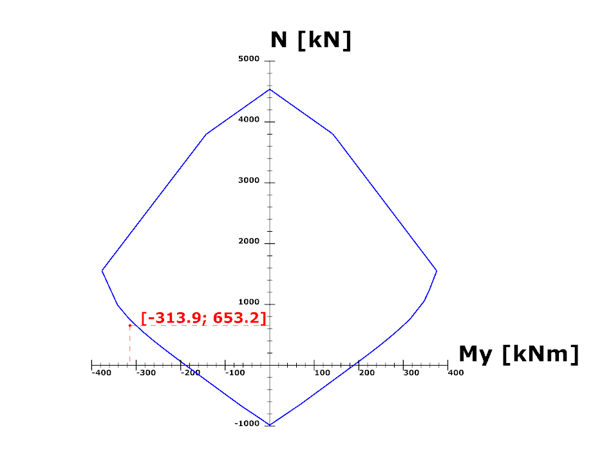
Did you know that you could use Consteel to calculate effective cross-section properties for Class 4 sections?
The classification of cross-sections is used to understand how local buckling affects the strength and rotation capacity of structural members. As stated in Eurocode 3 (EN 1993-3-3, Section 5.5), this classification helps determine whether a cross-section can reach its full resistance or if its behavior is limited by local instability.
Class 4 cross-sections are those in which local buckling occurs before the material reaches the yield stress in one or more parts. Because of this, their resistance must be calculated using effective section properties that take into account the reduction caused by local buckling.
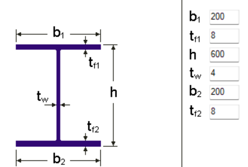
Typical Class 4 sections are characterized by slender elements with high width-to-thickness ratios. These commonly include thin webs or flanges, hollow sections (RHS/CHS) with slender walls, thin-walled cold-formed profiles such as C- or L-sections, and welded I-sections with slender webs. In this example, we consider a welded I-section with the following geometric parameters:
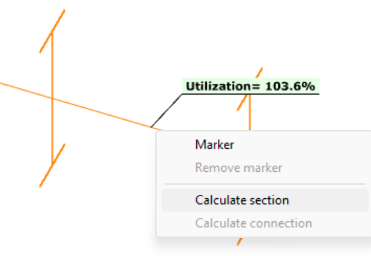
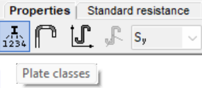
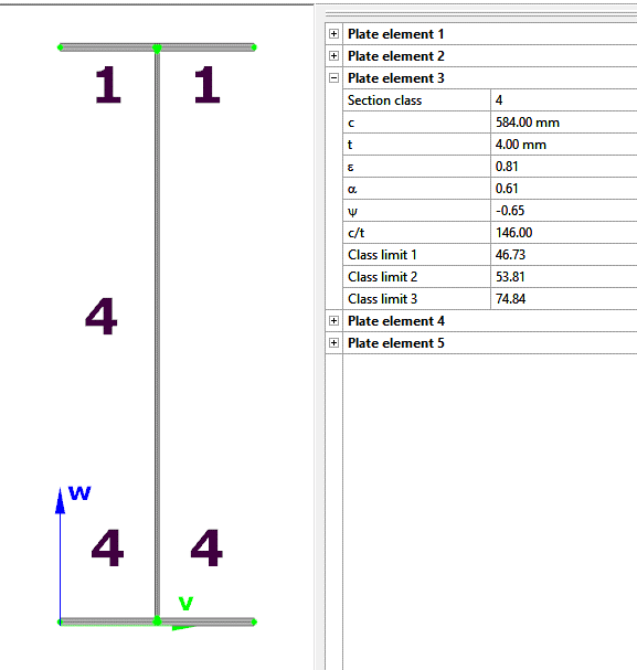
In Consteel, we can then see the section classification from the Global Checks tab. After selecting the investigated section either in the model or from the table and clicking on the Calculate Section option, and then choosing the Plate Classes in the Properties tab.
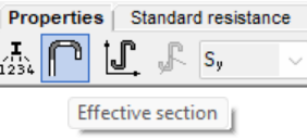
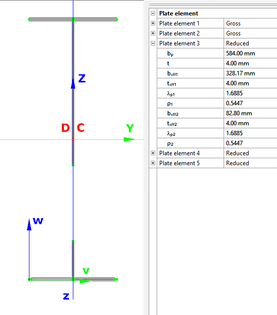
The effective section properties can then be viewed using the second option in the Properties tab.
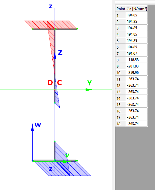
In addition, stresses can be visualized by clicking on the Stresses icon. They can be represented either as a colored figure or as a 3D diagram.
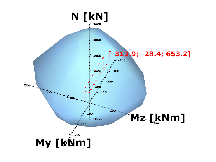
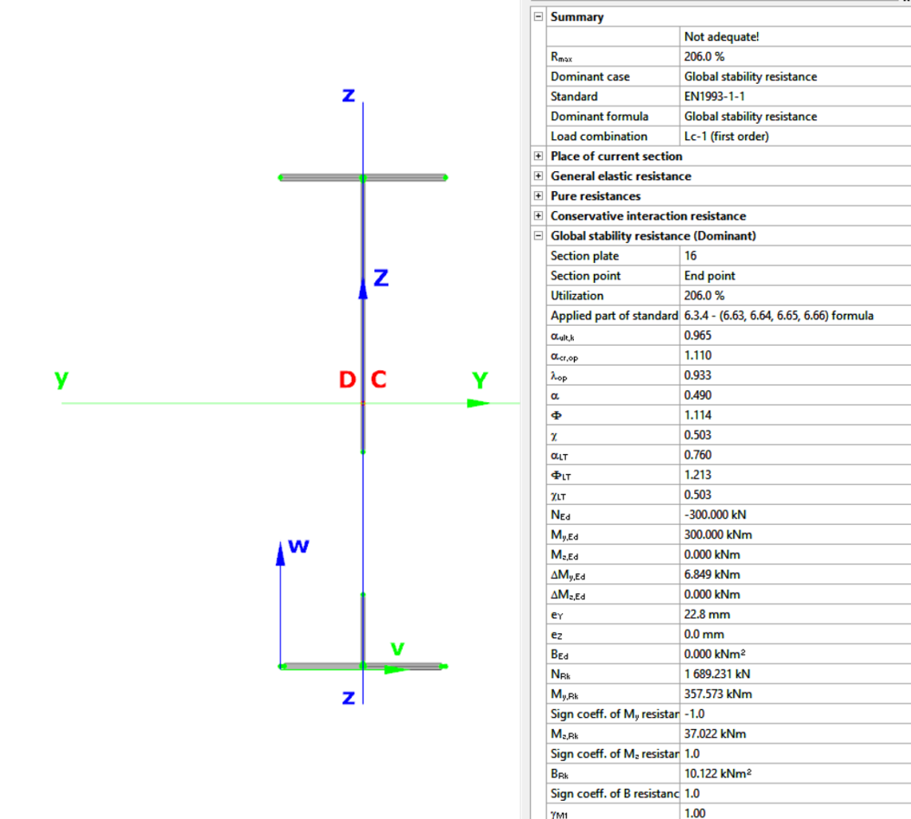
For Class 4 sections, the Standard Resistance tab in the section module provides a complete assessment for the selected loading case.
The section module performs all necessary calculations according to the Eurocode (EN 1993-1-1 and relevant parts of EN 1993-1-5), including general elastic resistance, pure case resistance, conservative interaction checks, and web buckling analysis.
All resistances are calculated using the effective section properties to account for local buckling, and the module identifies the dominant case to ensure all relevant checks are covered.
Download the example model and try it!
Download modelIf you haven’t tried Consteel yet, request a trial for free!
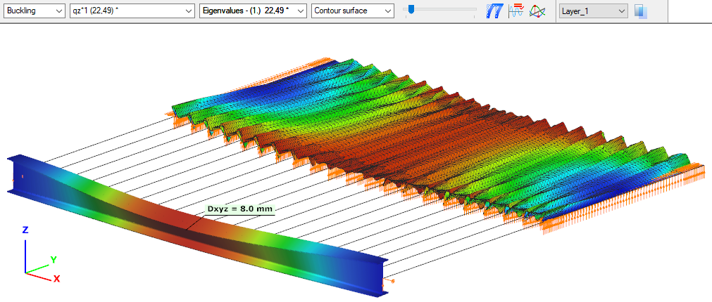
Try Consteel for freeDid you know that you could use Consteel to Consider the shear stiffness of a steel deck as stabilization for steel members?
In many practical steel structures, trapezoidal decking is treated only as a load-bearing surface. In reality, when properly connected to the supporting members, it behaves as a shear diaphragm and contributes to the overall stability of the structure. This effect can be directly taken into account in Consteel by applying shear field stiffness to beam elements.

The stabilizing effect comes from the in-plane shear stiffness of the deck. Under horizontal loading, the sheeting deforms and transfers forces between structural members. This behavior can be described by a single parameter, the shear stiffness (S), which represents the resistance of the diaphragm against deformation.
The overall stiffness is influenced by several components, including the shear deformation of the sheet, profile geometry, fastener slip, and connection flexibility. These contributions together define how effectively the deck can restrain phenomena such as lateral-torsional buckling.
A key requirement for this behavior is proper fastening. Typically, the sheeting must be connected along its edges and fixed to supporting members at each rib to ensure reliable diaphragm action.
In engineering practice, shear stiffness is determined using standardized or manufacturer-based methods rather than detailed analytical models. Consteel supports several established approaches:
- Schardt/Strehl method (DIN 18807), based on parameters describing shear and warping deformation
- Improved Schardt/Strehl method, including the effect of fastener spacing
- Bryan/Davies method, considering additional structural parameters
- Eurocode-based method, using general geometric properties of the sheeting
These methods differ in complexity and required input data, but all aim to provide a realistic stiffness value for use in global analysis. If the sheeting is not fixed at every rib, the calculated stiffness must be reduced accordingly.
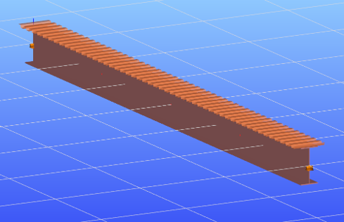
The shear field object in Consteel allows engineers to include the diaphragm effect without detailed shell modeling. The calculated shear stiffness can be assigned directly to beam elements, providing additional lateral restraint.
The process involves selecting a trapezoidal sheet profile, choosing the appropriate calculation method, and defining the relevant geometric and connection parameters. The software then determines the stiffness and incorporates it into the structural model.
Including shear stiffness in the analysis can lead to higher critical load factors and reduced displacements, resulting in more efficient structural designs. However, it also means that the decking becomes part of the stabilizing system.
Any later modifications to the sheeting, such as openings or changes in fastening, may reduce this effect and should therefore be carefully assessed.
The shear stiffness of trapezoidal steel decking provides a measurable and often significant contribution to structural stability. By incorporating this effect in Consteel, engineers can achieve more realistic analysis results and optimize their designs while maintaining structural safety.
Download the example model and try it!
Download modelIf you haven’t tried Consteel yet, request a trial for free!
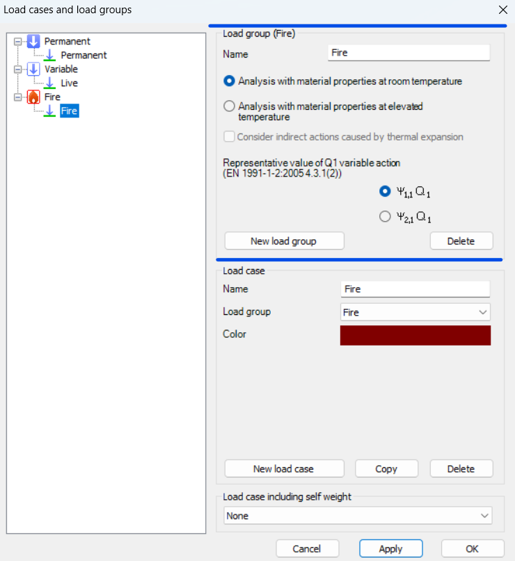
Try Consteel for freeDid you know that you could use Consteel to perform structural analysis at room and elevated temperatures as part of design process for fire resistance?
In structural fire engineering, the mechanical response of steel structures must be evaluated under both room and elevated temperature conditions. Consteel permits this by incorporating temperature-dependent material behavior directly into the finite element analysis, allowing engineers to assess not only resistance but also changes in global structural response.
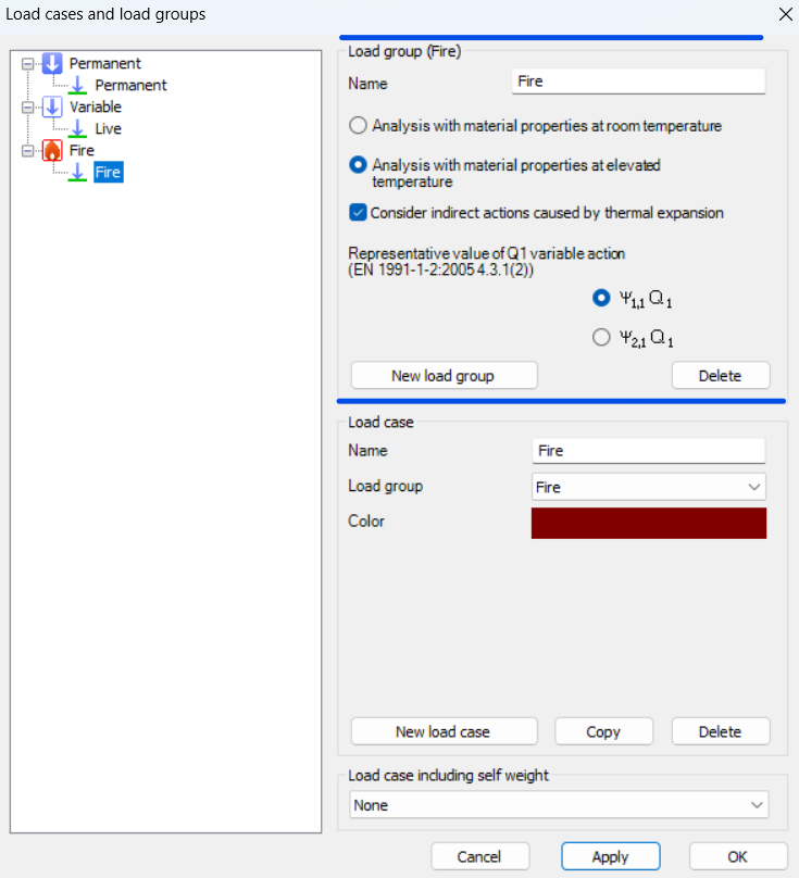
During fire analysis, Consteel determines the steel temperature and applies the corresponding reduction in material properties, most notably the modulus of elasticity and yield strength. These reductions are defined according to Eurocode 3 (EN 1993-1-2). As a result, the calculated internal forces and deformations reflect both the applied loads and the effects of thermal expansion and stiffness degradation. The analysis is performed on the global structural model, so compatibility effects and force redistribution are inherently captured.
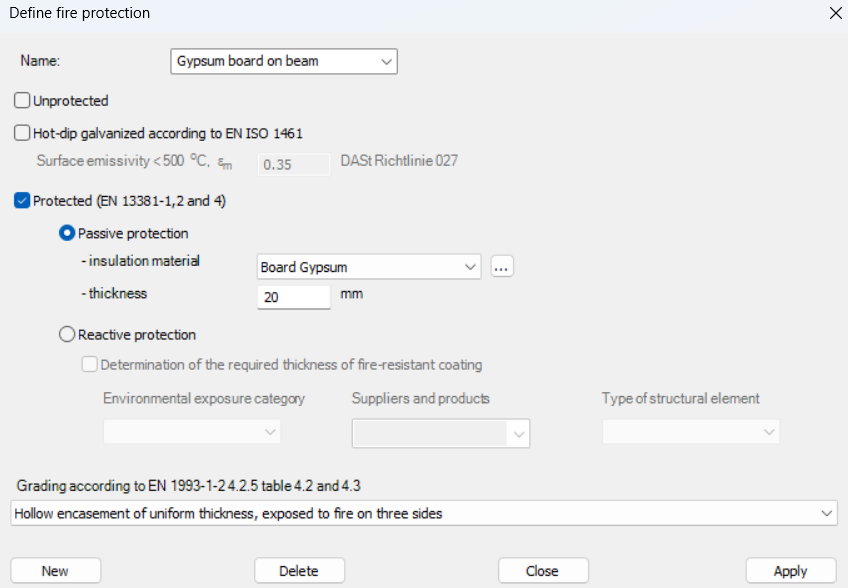
Fire exposure is defined using nominal fire curves (Standard, External, Hydrocarbon), together with a specified fire resistance time. In addition, the model allows assignment of fire protection conditions, including unprotected members, hot-dip galvanized surfaces, and protected elements with either passive insulation or reactive (intumescent) coatings. These definitions influence the temperature development in the structural members and, consequently, their mechanical response.
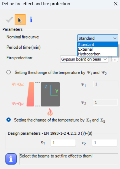
For design verification, Consteel applies the resistance models of EN 1993-1-2. Cross-section resistance is calculated using temperature reduction factors, depending on the type of internal force and cross-section class. Checks are performed for tension, compression, bending, and shear, as well as their interaction. For global stability, the software uses the Eurocode general method with modified buckling curves and reduction factors adapted for elevated temperatures.
In addition to elevated-temperature analysis, Consteel supports a complementary approach based on room-temperature analysis for critical temperature determination. In this case, the structural analysis is carried out with ambient material properties, and the objective is to find the temperature at which the reduced resistance equals the internal forces from the governing load combination. This method is particularly relevant for members with intumescent coatings, where the coating performance depends on the critical steel temperature. The calculated critical temperature can then be used to determine the required coating thickness based on product-specific data.
The difference between these two approaches can be illustrated using a two-storey frame model.
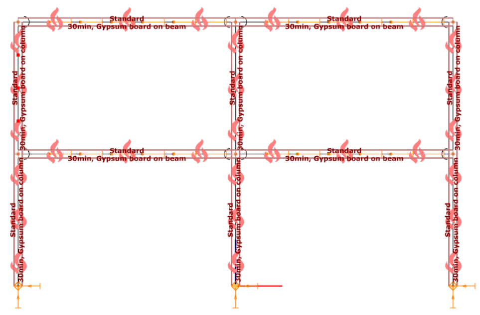
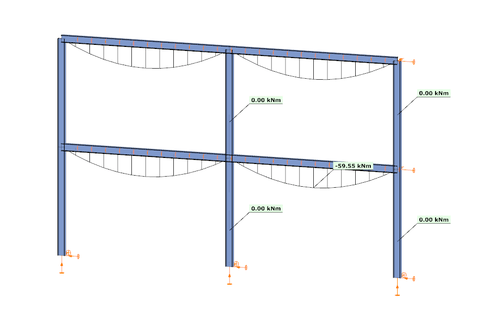
In the first case, the analysis is performed at room temperature. The beams develop a bending moment of approximately –59.55 kNm, while the columns carry primarily axial forces and show no significant bending moment along their length. This is consistent with the expected behavior based on the initial stiffness distribution of the structure.
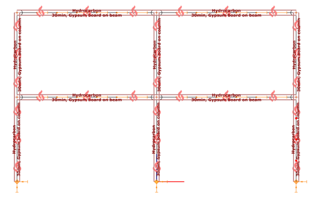
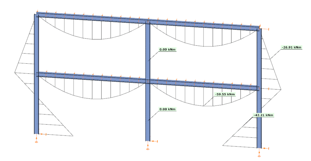
In the second case, the analysis is performed at elevated temperature, where reduced stiffness and thermal expansion are taken into account. The beam moment remains –59.99 kNm, but the internal force distribution in the structure changes. Bending moments appear in the columns, reaching approximately –26.91 kNm and –42.21 kNm at midspan.
This difference is a direct consequence of two coupled effects. First, the reduction in modulus of elasticity decreases the stiffness of heated members, modifying the relative stiffness distribution within the frame. Second, thermal expansion introduces additional deformations, which are partially restrained by the structural system. In statically indeterminate structures, such restraint generates additional internal forces, leading to redistribution of moments and the appearance of bending in members that were previously dominated by axial force.
From an engineering perspective, this comparison highlights that the internal force system under fire conditions is not a simple scaled version of the ambient-temperature state. Instead, it is the result of a different equilibrium condition, influenced by temperature-dependent material behavior and compatibility effects.
By allowing both types of analysis within the same model, Consteel provides a consistent framework to evaluate these phenomena. This supports more accurate assessment of structural performance in fire and enables informed decisions regarding fire protection and member design.
Download the example model and try it!
Download modelsIf you haven’t tried Consteel yet, request a trial for free!
Try Consteel for freeDid you know that you could use Consteel to calculate the elastic critical moment of a member subject to arbitrary loading and boundary conditions?
Calculating the elastic critical moment can quickly become difficult when beams have tapering, unusual restraints, or complex loads. Consteel simplifies the process and gives a quick, accurate result for any situation.
The elastic critical moment for lateral-torsional buckling is the theoretical bending moment at which a beam, free to sway sideways and twist, becomes unstable and buckles elastically, before yielding, representing the absolute upper limit of elastic stability for beam bending. It depends on: cross-section stiffness properties (Iz, Iw), material (E, G), span / buckling length, restraint to lateral displacement and to warping at the restraints, and on the shape of the moment diagram (via factors C1, C2, C3).
For doubly symmetric I- or H-sections with constant cross-section, uniform bending, and classical boundary conditions, the elastic critical moment Mcr can be calculated using the analytical formula:
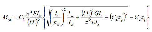
However, for arbitrary support conditions and loading scenarios, the calculation becomes significantly more complex, and the classical formula is no longer applicable. In such cases, specialized software such as LTBeam or Consteel is required.
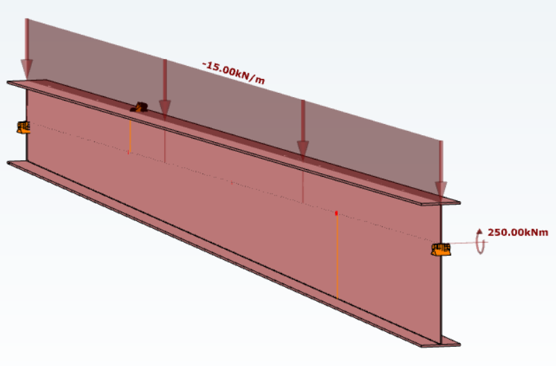
Let’s consider a tapered, welded I-section with pinned supports at both ends and two intermediate restraints, one at the bottom flange and one at the top flange. In addition to the uniform distributed load, a bending moment is applied at one end of the beam.
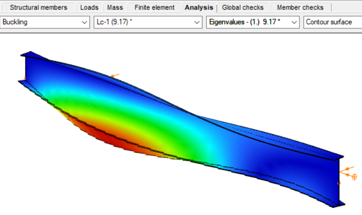
By performing a buckling analysis in the Analysis tab, the buckling shapes and the critical load factor (αcr) can be obtained. The elastic critical bending moment of the beam can be then calculated by multiplying the critical load factor by the maximum bending moment.
Consteel uses seven-degree-of-freedom finite element that fully accounts for tapering effects, torsion, and warping, key components in accurately capturing the true 3D behaviour of steel members. The seventh degree of freedom represents cross-sectional warping, which becomes visible in the buckling shape as the flanges move out of the plane of the cross-section.
Download the example model and try it!
Download modelIf you haven’t tried Consteel yet, request a trial for free!
Try Consteel for freeA Consteel lehetőségek széles skáláját kínálja a teherkombinációk szűréséhez, amely határállapot, tehereset, valamint analízis eredmények és kihasználtságok alapján is történhet. Szűrők különböző kombinációinak alkalmazásával a tervezési folyamat tudatosabbá válhat és csökkenhet a számítási idő.
Szűrési lehetőségek
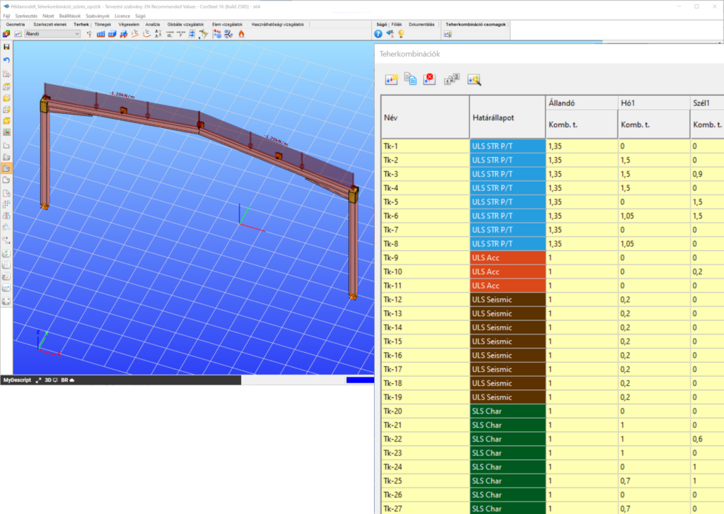
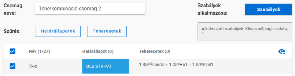
A szűrést a Teherkombináció csomag megadása nevű dialóg on lehet elvégezni.
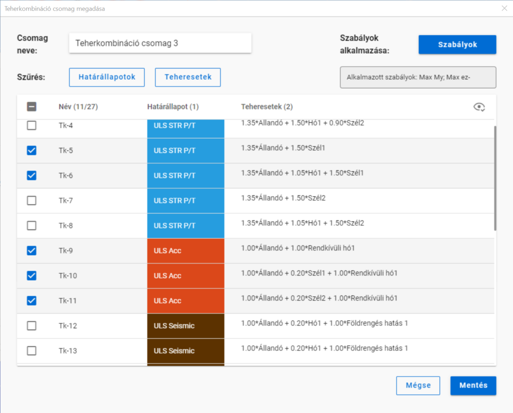
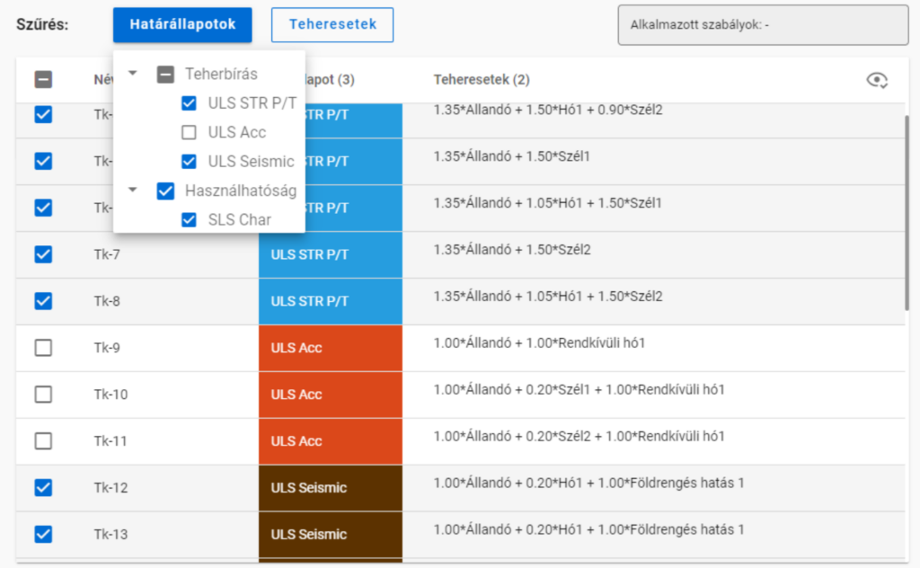
A határállapotok és teheresetek szerinti szűrést az azonos nevű gombok alatt lenyíló jelölőnégyzetekkel lehet végrehajtani.
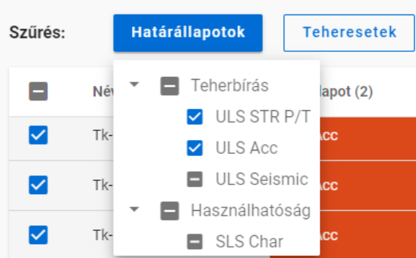
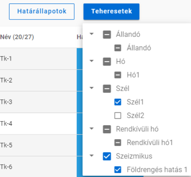
A jelölőnégyzeteknek három állása van. Nem csak kiválasztásra használhatóak, hanem egyben az adott teherkombináció csomag tartalmát is mutatják. Kézzel csak bepipált vagy üres állapotra kapcsolhatók, a köztes állás akkor jelenik meg, ha egyéb szűrőket alkalmazunk.
A határállapotok és teheresetek szerinti szűrést számítási eredmények nélkül is lehet alkalmazni.
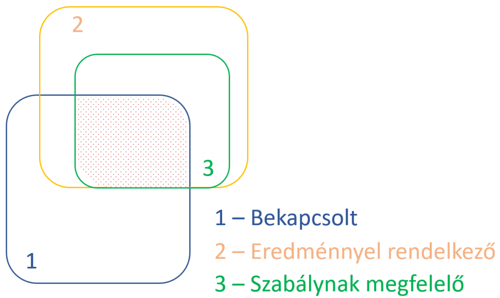
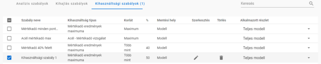
A szabályok szerinti szűrés viszont minden esetben analízis vagy tervezési eredményeken alapszik. A különböző típusú szabályokat egyszerre vagy egymás után is lehet alkalmazni, hogy kiválasszuk a kívánt teherkombinációkat.
Amikor egy szabályt alkalmazunk, a filter megvizsgál minden teherkombinációt, ami ki volt választva a Teherkombináció csomag megadása ablakban -akár kézzel, akár határállapota vagy a benne lévő tehereset alapján-, minden olyan végeselem pontban, amit a szabály megkíván. Azok a teherkombinációk, amik megfelelnek a szabálynak, kiválasztva maradnak, míg azok, amelyek nem, nem lesznek többé kijelölve.
- Analízis szabály alkalmazásával deformációk vagy igénybevételek alapján választhatunk ki kombinációkat. Az analízis eredményeket a szabály megadásától függően minden végeselem pontban vagy csak az elemvégeken vizsgáljuk (pl. kapcsolatokhoz). Deformációkat csak SLS, míg igénybevételeket csak ULS kombinációkban vizsgálunk.
- Kihajlás szabállyal azok a teherkombinációk választhatók ki, amelyekhez tartozó rugalmas kritikus teherszorzó (első kihajlási sajátérték) kisebb a megadott értéknél.
- Kihasználtsági szabállyal a teherkombinációkat a kiválasztott részletmodell minden végeselem pontjában meghatározott kihasználtságok alapján lehet szűrni. Acél elemek esetén a kihasználtságok elérhetők minden szabványos vizsgálatból, mint pl. általános rugalmas szilárdsági ellenállás, tiszta igénybevételi ellenállás, interakciók és globális stabilitásvizsgálat. A filter csak ULS kombinációkra alkalmazható.
Különböző típusú szűrők kombinálása
A háromféle szűrőt lehetséges és érdemes együtt használni, azonban fontos tudni, hogy a szabályok szerinti szűrést csak azokon a kombinációkból válogat, amik ki vannak választva és van hozzájuk megfelelő számítási eredmény.
Vegyünk egy példát!
Egy egyszerű síkbeli keretmodell, amiben 27 teherkombinációt generáltunk többféle határállapotban. Az analízis és szabványos tervezési eredmények rendelkezésre állnak az összes teherkombinációban.
Alkalmazzunk egy kihasználtsági szabályt, amely kiválasztja azokat a teherkombinációkat, ahol a legnagyobb mértékadó kihasználtság 50% felett van.
Ekkor négy teherkombinációt kapunk:
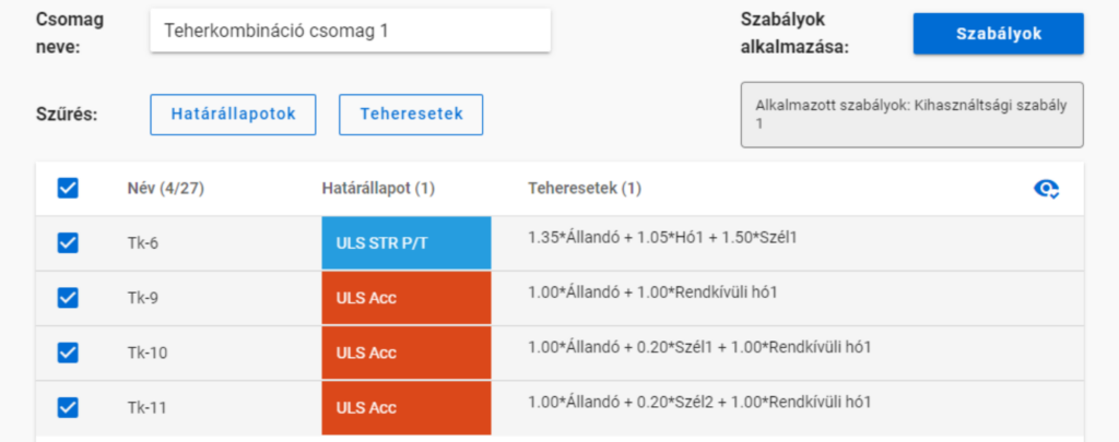
De ha az 50%-os szabály alkalmazása előtt kikapcsoljuk a rendkívüli teherkombinációkat,
akkor a szabály alkamazása után már csak egy kombinációnk marad.
Több szabály alkalmazása
Több szabály együttes alkalmazása esetén a létrejövő teherkombináció-lista azoknak a listáknak az összege lesz, amik a szabály külön-külön való alkalmazása esetén jöttek volna létre.
gateIntroduction
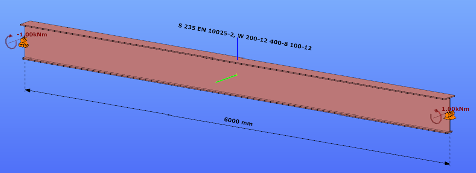
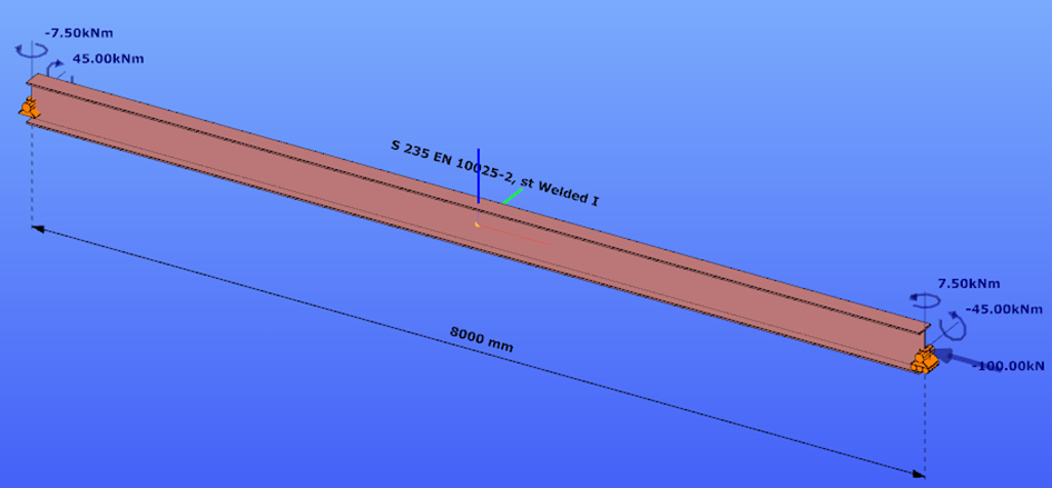
This verification example studies a simple fork supported beam member with welded section (flanges: 200-12 and 100-12; web: 400-8) subjected to bending about major axis. Constant bending moment due to concentrated end moments and triangular moment distribution from concentrated transverse force is examined for both orientations of the I-section. Critical moment and force of the member is calculated by hand and by the Consteel software using both 7 DOF beam finite element model and Superbeam function.
Geometry
Normal orientation – wide flange in compression
Constant bending moment distribution
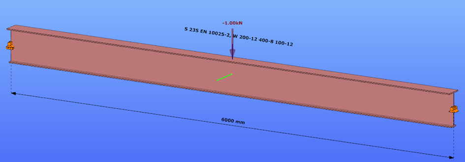
Triangular bending moment distribution – load on upper flange
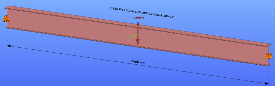
Triangular bending moment distribution – load on bottom flange
Reverse orientation – narrow flange in compression
Constant bending moment distribution
Triangular bending moment distribution – load on upper flange
Triangular bending moment distribution – load on bottom flange
Calculation by hand
Factors to be used for analitical approximation formulae of elastic critical moment are taken from G. Sedlacek, J. Naumes: Excerpt from the Background Document to EN 1993-1-1 Flexural buckling and lateral buckling on a common basis: Stability assessments according to Eurocode 3 CEN / TC250 / SC3 / N1639E – rev2
Normal orientation – wide flange in compression
Constant bending moment distribution
Reverse orientation – narrow flange in compression
Computation by Consteel
Version nr: Consteel 15 build 1722
Normal orientation – wide flange in compression
Constant bending moment distribution
- 7 DOF beam element
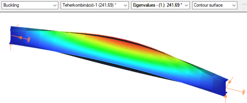
First buckling eigenvalue of the member which was computed by the Consteel software using the 7 DOF beam finite element model (n=25). The eigenshape shows lateral torsional buckling.
Superbeam
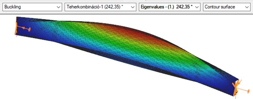
First buckling eigenvalue of the member which was computed by the Consteel software using the Superbeam function (δ=25).
Introduction
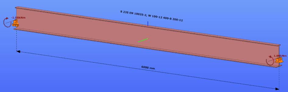
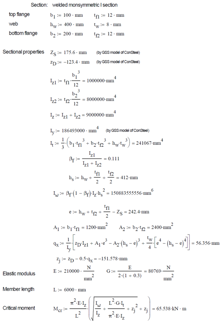
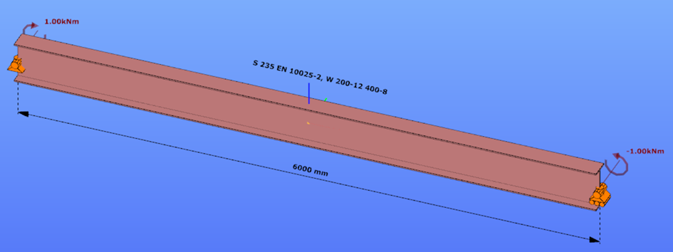
This verification example studies a simple fork supported beam member with welded section (flanges: 200-12; web: 400-8) subjected to bending about major axis. Constant bending moment due to concentrated end moments and triangular moment dsitribution from concentrated transverse force is examined. Critical moment and force of the member is calculated by hand and by the Consteel software using both 7 DOF beam finite element model and Superbeam function.
Geometry
Constant bending moment distribution
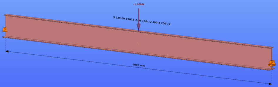
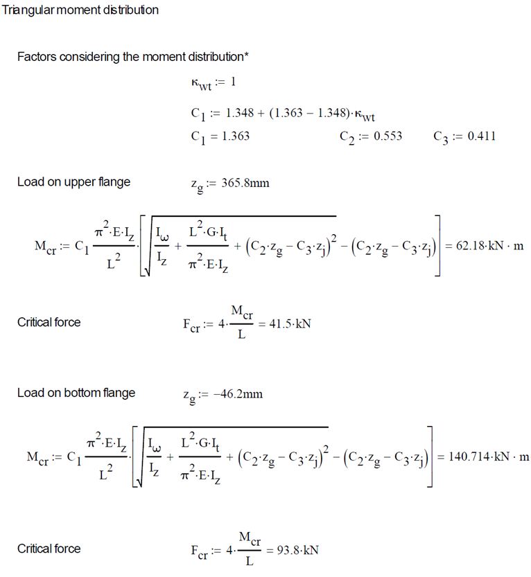
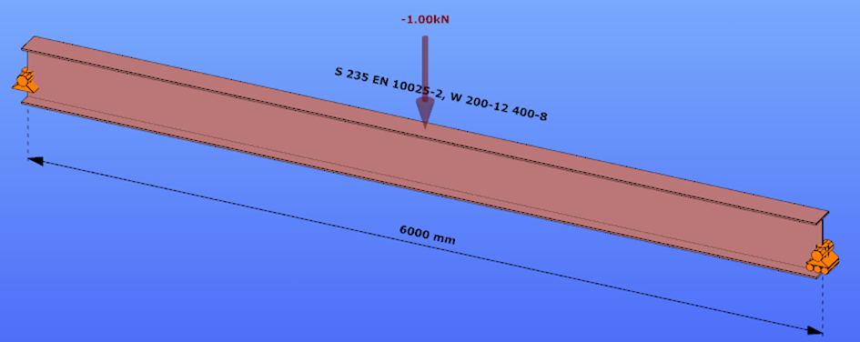
Triangular bending moment distribution – load on upper flange
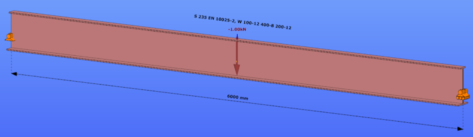
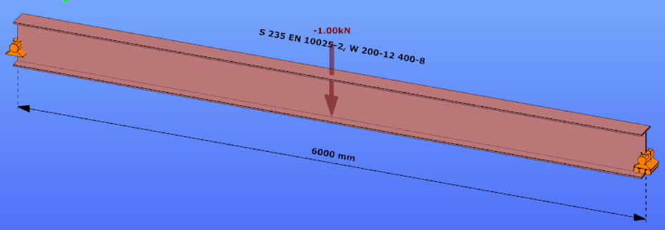
Triangular bending moment distribution – load on bottom flange
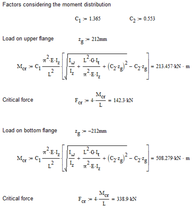
Calculation by hand
Constant bending moment distribution

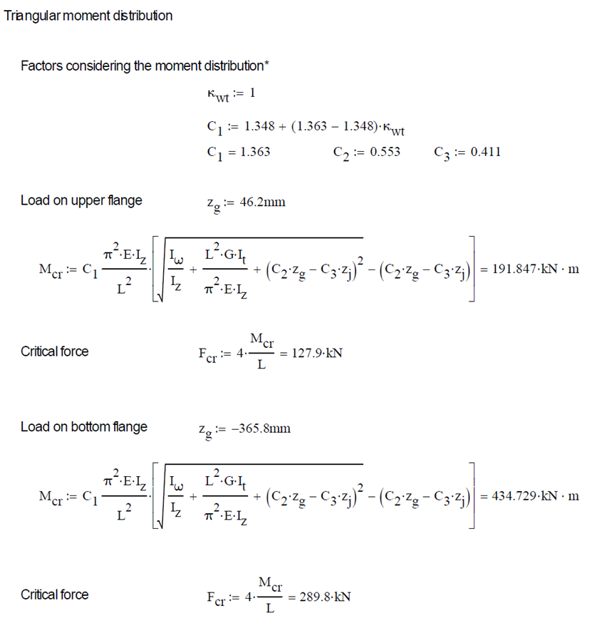
Triangular bending moment distribution
Computation by Consteel
Version nr: Consteel 15 build 1722
Constant bending moment distribution
7 DOF beam element
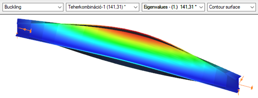
First buckling eigenvalue of the member which was computed by the Consteel software using the 7 DOF beam finite element model (n=16). The eigenshape shows lateral torsional buckling.
Superbeam
First buckling eigenvalue of the member which was computed by the Consteel software using the Superbeam function (δ=25).
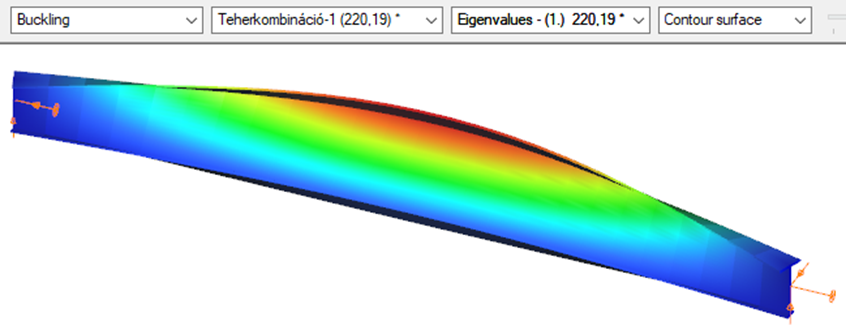
Triangular bending moment distribution – load on upper flange
7 DOF beam element
First buckling eigenvalue of the member which was computed by the Consteel software using the 7 DOF beam finite element model (n=16).
Superbeam
First buckling eigenvalue of the member which was computed by the Consteel software using the Superbeam function (δ=25).

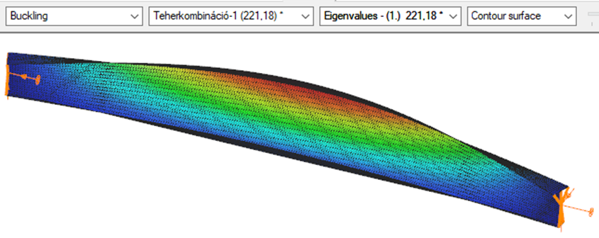
Triangular bending moment distribution – load on bottom flange
(tovább…)Introduction
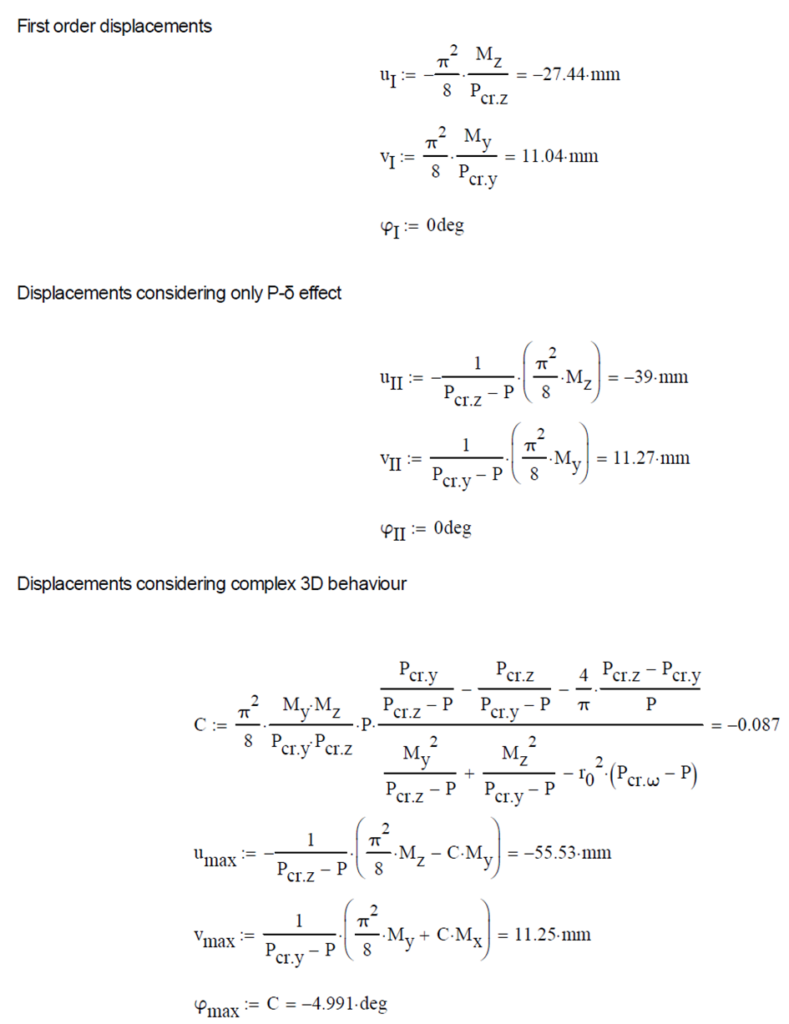
This verification example studies a simple fork supported beam member with welded section equivalent to IPE360 (flanges: 170-12,7; web: 347-8) subjected to biaxial bending due to concentrated end moments and compression due to axial force. Second order deformations of the middle cross-section of the member are calculated by hand and by the ConSteel software using both 7DOF beam and shell finite elements and Superbeam function. In addition to the verification, the difference between modelling with 6DOF and 7DOF elements is demonstrated.
Geometry
Calculation by hand
The first order and the simple amplified (P-δ) deformations can be analitically calculated by the well known formulas. The calculation of the second order deformations considering true, three-dimensional behaviour of the beam is however so complicated that there are only approximate analitical formulas available for hand calculation. The formula below can be found in Chen, W. and Atsuta, T.: Theory of Beam-Columns, Vol. 2: Space behavior and design, McGRAW-HILL 1977, p. 192

Computation by Consteel
Version nr: Consteel 15 build 1722
First order
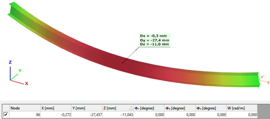
Second order – 6DOF beam element
The second order deformation of the member which was computed by the ConSteel software. It is visible that there is no torsion, only increments of the lateral displacements due to P-δ effect:
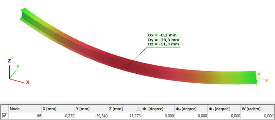
Second order – 7DOF beam element
The second order deformation of the member which was computed by the ConSteel software using the 7DOF beam finite element model (n=16). It is visible that there is torsion and further increment in the lateral displacement (Dy):
Second order – Shell finite element
The second order deformation of the member which was computed by the ConSteel software using the shell finite element model (δ=25mm):
Second order – Superbeam
The second order deformation of the member which was computed by the ConSteel software using the Superbeam model (δ=25mm):