Introduction
In Consteel there are several opportunities to place the point supports you need in a quick and effective way.
Multiple placing of column bases
In case you imported a model from another software and there are no supports defined or for some reason you decided to define the supports after modelling the whole building, it is not necessary to place every support one-by-one by clicking the end of all of the columns. To save time, click Multiple placing function (black arrow) on Point support dialog after setting the support type and select the columns with selection window.
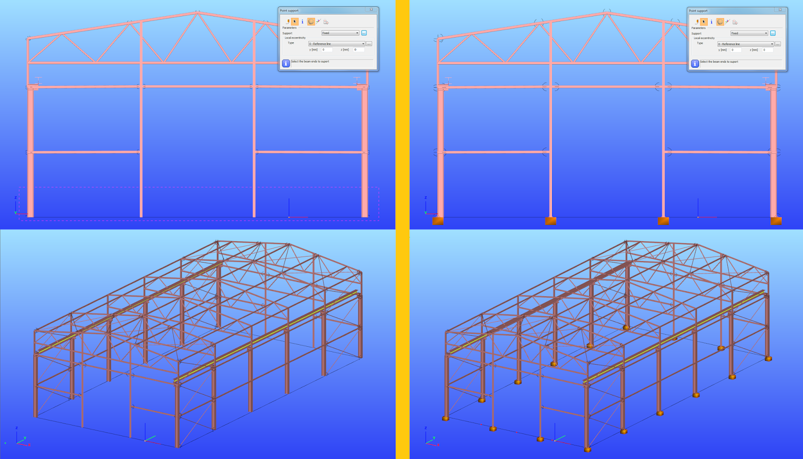
Multiple placing on members
It is also possible to use the Multiple support function of the same Point support dialog to place the supports representing the girts/purlins and flange braces of a frame. Distribution and eccentricity of the supports can be defined. If the distribution given is not suitable for the member, Consteel will ignore the distances which are outside the member length (3rd 1600mm on the picture below) even if there is another member with the same reference line.
gateIntroduction
The Frame corner wizard is a useful additional function for modelling and analyzing the corner region in order to consider its special behavior.
What is it for
The frame corner zones have usually significantly different behavior than the beam elements connected to each other without significant angle between their reference line. Frame corner wizard recognises the corner regions and applies special methods during modelling, buckling analysis and global checks. Using this function will provide very similar analysis results compared to where the frame is modelled with shell elements.
But in order to that, the topology of the frame corner must be defined by the user. Four different types can be chosen. The 7. DOF displacement is transferred differently in every case. To learn more technical details of the frame corner types, please see our user manual.
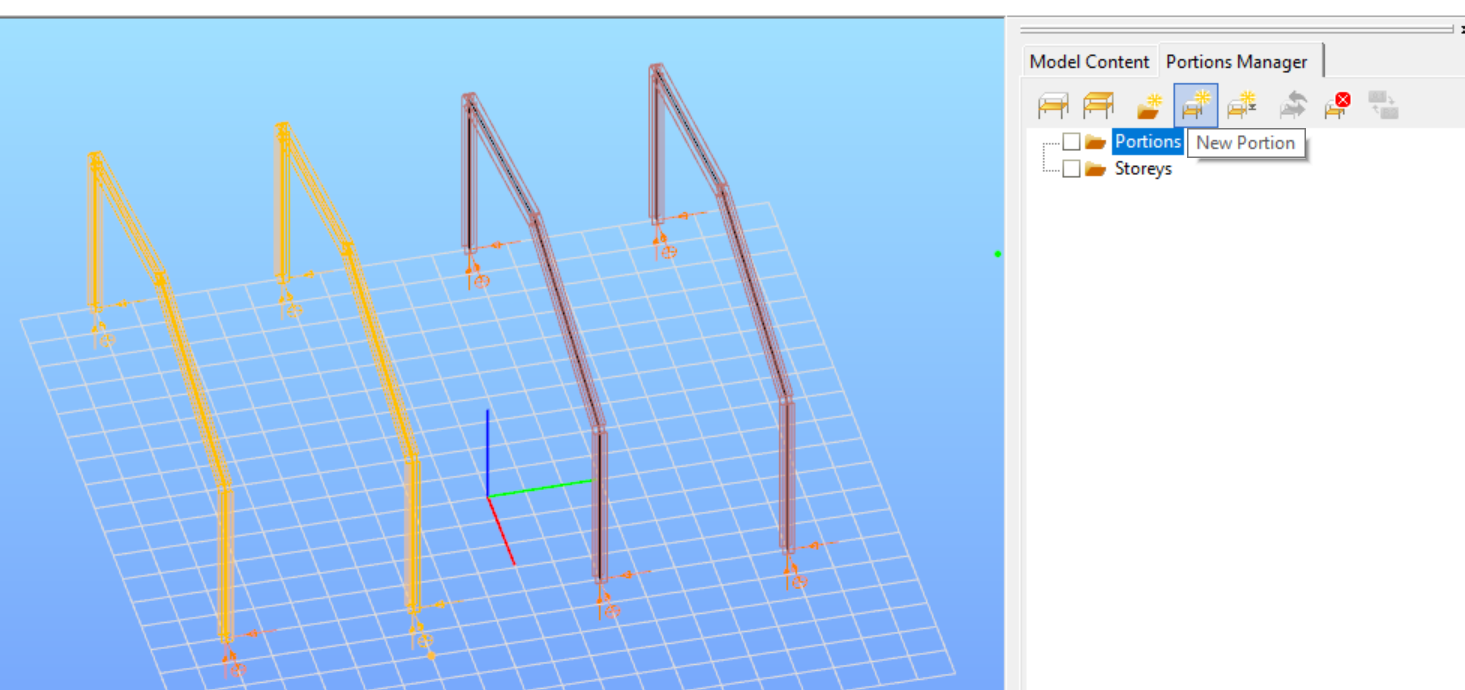
How to use it
At first define Portions of the model containing all the structural elements you intend to connect with the same type of corner topology.
Introduction
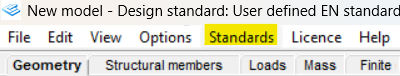
In Consteel a great variety of EN National Annexes can be used for structural design. It is possible to review the existing annexes in the Standards menu. In case you can not find the annex you need, you are still able to define a new, custom one in an easy way.
How it works
The following annexes are available in Consteel 19:
EN Recommended, Hungarian, Dutch, Finnish, Singapore, Portuguese, Swedish, Austrian, Polish, German, Bulgarian, Greek, Cyprian, UK, Croatian, French and Danish. Spanish, Italian and Romanian standards are EN-conform codes but not officially NA’s.
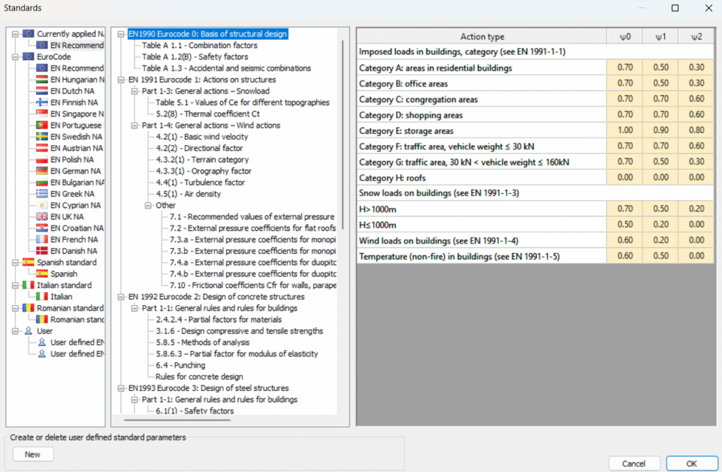
By selecting a standard on the left side of the Standards dialog, all of the parameters, combination factors, safety factors can be checked by chapters.
If a user defined annex is necessary, it can be created by selecting the existing annex which is the most similar in parameters to our needs, and then by clicking the New button on the bottom left side of the dialog. With this action a user defined annex is generated having the same parameters as the selected annex before. The difference is that the parameters of the copy are editable, and so the necessary set of parameters can be used for the design.

Introduction
There are different ways to evaluate the stability of a structure. It is important to know the differences between those methods and the limits of applicability but it is also important to recognize the equalities in pure cases.
Methods of stability design
In Eurocode 1993-1-1, and so in Consteel, there are 3 methods to verify the stability of a model:
- Imperfection approach (described in Section 5.2 and 5.3)
The structural model is subjected to appropriate geometrical imperfections and after completing a second order analysis, only the cross section resistances need to be checked
- Isolated member approach ( described in section 6.3.1, 6.3.2 and 6.3.3)
The method is based on two essential simplifications:
- Structural member isolation: The relevant member is isolated from the global structural model by applying special boundary conditions (supports, restraints or loads) at the connection points which are taken into account in the calculation of the buckling resistance
- Buckling mode separation: The buckling of the member is calculated separately for the pure modes: flexural buckling for pure compression and lateral-torsional buckling for pure bending. The two effects are connected by applying special interaction factors.
- General method (described in section 6.3.4)
The basic idea behind the general method is that it no longer isolates members and separates the pure buckling modes, but considers the complex system of forces in the member and evaluates the appropriate compound buckling modes. The method offers the possibility to provide solutions where the isolated member approach is not entirely appropriate:
-The general method is applicable not only for single, isolated members, but also for sub frames or complete structural models where the governing buckling mode involves the complete frame.
-The general method can examine irregular structural members such as tapered members, haunched members, and built up members.
-The general method is applicable for any irregular load and support system where separation into the pure buckling modes is not possible.
Implementation of different approaches in Consteel
Isolated member approach is basically the reduction factor method and it can be performed in Member checks function in Consteel where it is possible to define the design parameters (e.g. effective length) by hand.
In Global checksfunction, cross-section and global buckling checks can be executed automatically according to the General method which does not require the direct introduction of effective lengths and other parameters depending on the distribution and combination of stresses along the member.
However, in pure cases (pure compression, or pure bending), buckling length calculated from general method can be equated with isolated member approach. In the following, a „how to” example will be shown on a pure compression column:
How can I get the buckling length of a certain member?
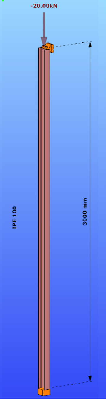
Parameters:
- Section: IPE100
- Material: S235
Main inertia around axes:
- Iy = 1708644 mm4
- Iz = 158056 mm4
Supports:
- x,y,zz on the top
- fixed on the bottom
Load: NED = 20 kN
Both the Isolated member approach and the General method require to calculate the slenderness value of the member. In case of the first method this is done through the use of buckling lengths. By using the General Method, the slenderness is calculated as the ratio of two amplifiying factors.
For the calculation of the equivalent buckling length we will need the first amplifier only, called critical elastic factor or alpha critical factor, obtained through a numerical analysis called linear buckling analysis.
Determination of alpha critical factor with buckling analysis:
Alpha critical factor: Minimum amplifier for the design loads to reach the elastic critical resistance of the structural component with regards to lateral buckling.
gateIntroduction
Joint orientaion can be chosen by the graphical display of the Place joint on the model function.
How it works
If there is only one option how to place a joint e.g. a single beam connected to a column, the orientation of the joint on the graphical display has no effect on the orientation of the placed joint.
IF:
- There is more than one option on the placement and
- The geometry of the connected members are completely the same
the orientation of the joint on the graphical display will determine the orientaion of the placed joint.
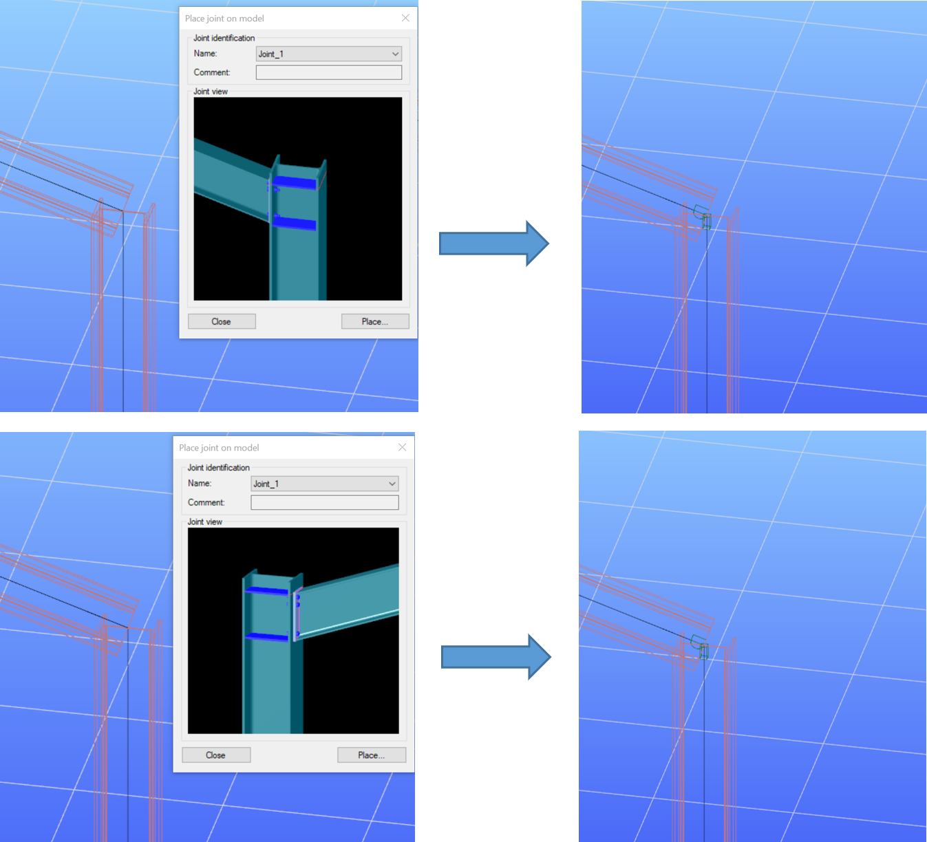
Please see below an example for two different orientations of the same joint. In the first row of pictures the joint is placed in a way that the longer connection plate with the bolts outside the beam flanges is on the right side (‘Right flange’ on the picture). You can see in Consteel Joint that the higher (152 kNm) moment acts on the right side.
In the second row, the same joint is placed with opposite orientation – the long connection plate on the left side. It is visible that the 152 kNm is now on the other side (the one with the shorter plate and bolts inside the flanges).
gateIntroduction
How can you place surface wind loads, when you have a custom shaped flat roof instead of the standard types you can see in Eurocode?
How to do that
Create a load transfer surface to the roof with Draw polygon option at Edit load transfer surface dialog.

Open Create surface load dialog and choose Draw and Wind load option.
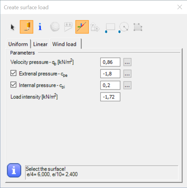
Set the parameters – load intensity will be calculated automatically:
Velocity pressure can be defined either manually or by clicking on the … and setting the parameters.
To calculate the zones and Cpe values click on the … at External pressure – Cpe. When defining the b and d values use the overall dimensions of the building of the current wind load direction. The zones will be calculated to cover this theoretical surface.
gateIntroduction
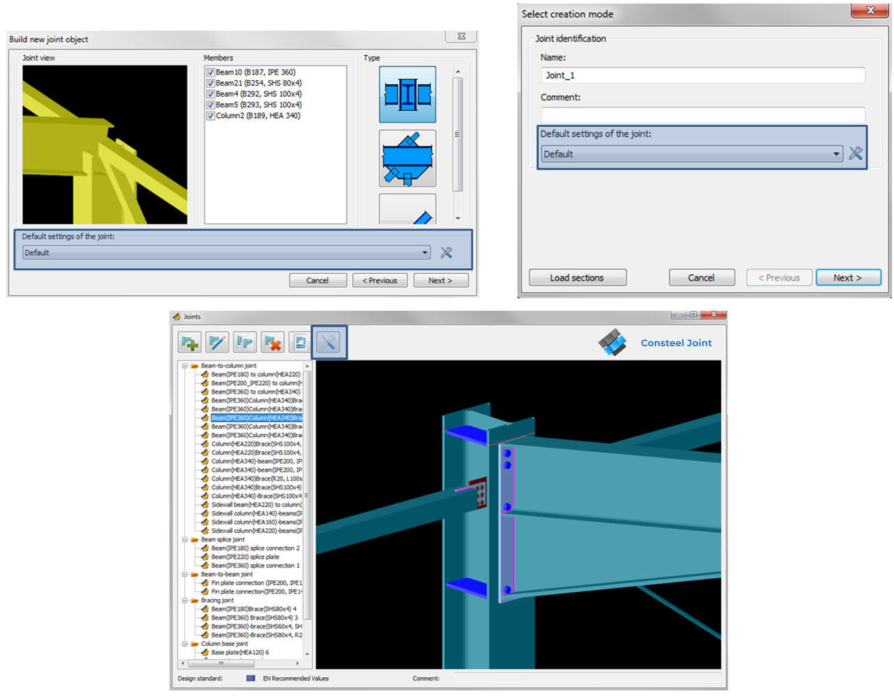
When you create a new joint either manually or by model, certain parameters are set to a default value e.g. weld sizes, method of weld design, bolt material and diameters, stiffener plate properties etc…
When you’re working on a large model, or simply want to design more joints in Consteel Joint, setting these default parameters one by one (e.g. if you have a specified palette of bolts or plate material) at each joints would take a lot of time. In this case, creating a new, user defined default setting can be very helpful, and can save you time.
How it works
The default joint settings can be modified at the Default joint settings dialog. It can be opened either when creating a new joint (manually or by model) or from Joints dialog.
Introduction
As you may already know, you can check the max, min and min-max envelope diagrams for (first and second order) analysis results in Consteel. But you can also create your own envelope figures…
How it works
By default the envelope figures can be requested for ULS and SLS combinations. These default options will use the results of all of the calculated ULS or SLS load combinations:
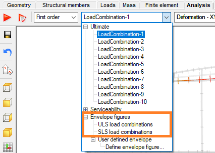
To create your own envelope figures:
If you choose the Define envelope figure… option from the load combinations dropdown menu of the analysis tab, you will get the User defined envelopedialog:
gateThe problem
Even if all of the load combination generation formulas of EN are implemented in Consteel for the automatic generation of combinations, standard formulas may not cover every necessary combination cases.
A quick fix
Of course in this case it is possible to define the missing combinations manually, but it is very likely, that the missing combinations are available, probably in a table form.
It is good to know, that Consteel is able to receive combination data, by the general Ctrl+C & Ctrl+V method. If you have the factors for load combinations stored in table form e.g. in Excel, just copy the data of the factors to the clipboard with Ctrl+C, and then Ctrl+V paste them into Consteels’s load combination table:
gateIntroduction
In case of a model with a lot of load cases (wind in different directions, with and without internal pressure, snow,seismic etc.), hundreds of load combinations can be generated acc. to EC but many of these combinations are irrelevant. Running an Analysis on all of the load combinations can take a lot of time, that could be saved, if the relevant load combinations are calculated only.
How to do that
- To find the relevant load combinations and save calculation time: At first perform only elastic first order analysis and global checks based on that. Even first order calculation can take much time if there are non-linear elements (practically tension-only rods) in the model. It is possible to temporarily change the non-linear elements to linear ones in order to let Consteel calculate the load combination analysis results with superposition of the load cases which is much quicker than calculation with non-linear elements.
- Under the Global checks tab, on the results table, selection of the load combinations with significant utilization can be done. (As on all tables in Consteel, multiple selection of different load combinations can be performed easily using Ctrl+select, or Shift+select features of Windows) With a right click on the selected combinations, use Select only these combination for the Analysis function to apply your choice to the next run.