Introduction
As it is important to have a clear overview of the structural model, the visualization of the analysis results is also essential when it comes to effective design process. From Consteel 15 we use an advanced method for deformation representation which makes it smooth and realistic.
Description
Civil engineering software in general use the traditional beam-type deformation representation where the section is shown on the deformation of the reference line. There are some consequences of this representation mode that can be disturbing for the users. The best example is an eccentric support, where the deformed shape is visualized as if the supported point would’ve moved. The reference line indeed moved but the supported point not – the representation can not show that.
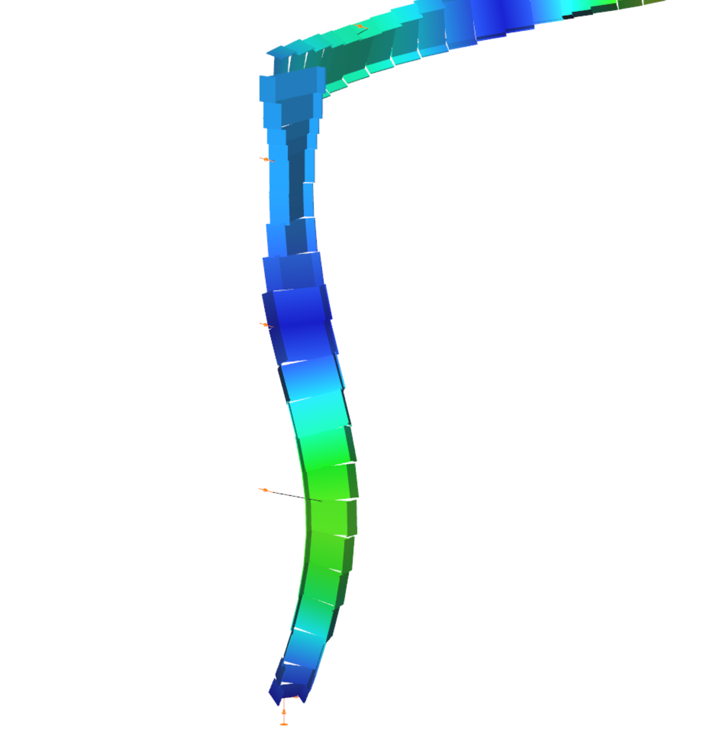
With Consteel’s advanced deformation representation not only the position of the reference line points are calculated and the section is only shown automatically, but the positions of all the decorated points of the section are calculated during a post-process and so it is possible to represent the real deformations. As a consequence it is also visible that the supported points stay in position.
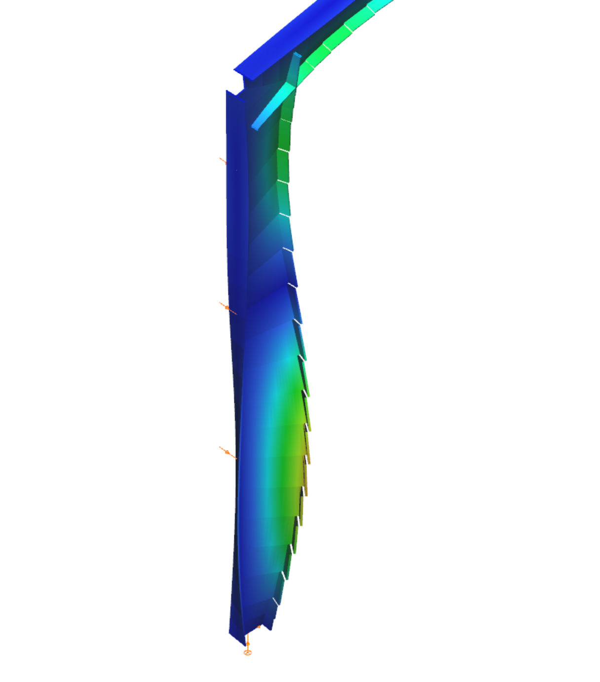
Civil engineering software in general use the traditional beam-type deformation representation where the section is shown on the deformation of the reference line. In Consteel 15 we use an advanced method for deformation representation which makes it smooth and realistic. The analysis results are the same, but with the improved visualisation the real 3D behavior of the structure can be better seen.
gate