fbpx

In this second article of our wind simulation series, we will delve into two critical topics of wind simulation for structural engineering. The first one is data processing, a collective name for the most relevant steps of the fluid-dynamics aided wind load generation, such as mesh creation, executing the simulation itself and extracting initial results. While the second one is a preliminary velocity-based validation example to broadly explain the influence of the simulation parameters, to ensure that the results are accurate and useful for practical design applications.

In the previous article [1], we covered the preprocessing steps for wind simulation, including setting up the geometry using simulation surfaces and boundary conditions (wind effects and directions). These parameters were mostly aligned with the underlying logic of the standards, therefore their interpretation is relatively straightforward. However, to carry on it is inevitable to briefly introduce the simulation related parameters too, which are divided into two categories.

The basic settings are the ‘mesh size on structure’ and the ‘mesh refinement factor’. The first one is the average edge size on the structure for both of the generated meshes, the finite element mesh for mechanical and the the finite volume mesh for fluid-dynamical purposes, presented in the previous article. While the refinement factor is used to increase the finite volume cell edge sizes at the boundaries of the simulation domain, which are considered to be far enough from the building, therefore it is not necessary to calculate field values as densely as it is calculated around the building according to the ‘mesh size on structure’ parameter, leading to quicker simulations.

Note: Larger mesh size on the structure and larger refinement factor values are leading to coarser mesh, therefore a quicker simulation but less accurate results!

The advanced settings are a set of parameters to control the simulation in the background, with default values usually leading to adequate results. However the goal of this article is to provide an insight in their influence.

The advanced settings of the simulation

To ensure a meaningful validation, a wind tunnel test was replicated, utilizing experimental data and computational parameters from the Architectural Institute of Japan (AIJ) Benchmarks [2] . The experiment was carried out in a small circulatory wind tunnel at the Technical Research Institute of Shimizu Corporation. The test model consisted of an acrylic cuboid with dimensions of 160 mm in height and 80 mm in width. The inflow wind velocity was set at 6.75 m/s, with a measured turbulence intensity of approximately 0.5%.

A 1:1:2 shape building case setup

Note: These validations were performed in a development version of our tool in the Grasshopper enviroment. In Consteel the tool focuses on the generation of wind loads, therefore can be utilized to extract pressure values.

Several key aspects were considered throughout the entire analysis process of the case study. Given that the model represents one of the simplest geometries encountered in practice, and that its structural behavior is straightforward to interpret within the context of standard guidelines, this case served multiple purposes. Primarily, it was used to underline the importance of conducting mesh independency tests prior to the actual simulation. As indicated in the table below, even for a simple geometry, the influence of mesh density proved to be significant — not only in terms of result accuracy but also from a performance perspective. For further investigations the “2000-4” mesh configurations was chosen, where the convergence of results became apparent.

Mesh size on structure [m]8000400020001000
Mesh refinement factor2345
Meshing runtime [s]18.365.361.2108.9
Cell number [-]136432150881264786495694
Simulation runtime [s]65.357.9151.1343.4
Iterations [-]264182260314
Fx+ [kN]197203.0205.6203.5
Fy+ [kN]94.494.589.989.7
Fy- [kN]94.594.489.889.8
Fz+ [kN]53.652.447.748.2

The next aspect was to emphasize the significance of mesh refinement, particularly along the edges. For example, finer mesh resolutions capture higher suction values on the side walls, though over smaller localized areas. Consequently, it is crucial to closely monitor the global reactions from the acting pressures influenced by a given mesh configuration, as presented in the table above.

Following the initial calibration tests, five different turbulence models (k – ε, k – ω, k – ω SST, RNG k – ε, Realizable k – ε) were compared based on their respective velocity fields.

These cases were executed simultaneously to assess the impact of full processor utilization. During the meshing process, the same mesh was applied in nearly all cases; however, the runtime increased to approximately 250 seconds, which is four times longer than when the cases were run separately. This clearly indicates that the previously reported runtimes were significantly influenced by the concurrent execution of parallel processes.

Note: It is also possible to run a single simulation case in parallel, which involves decomposing the computational domain and subsequently reconstructing it. However, this decomposition process also requires computational resources, meaning that running simulations in parallel does not always result in faster execution times.

Deviances of the velocity vectors (green – benchmark, orange – k-ε turbulence model)

The primary metric used for each case was the average directional deviance of the velocity vectors obtained by simulation from the benchmark experiment velocity vector, where 0 indicates parallel vectors and 1 indicates perpendicular vectors. Across all scenarios, similar behavior was observed in the wake region of the building, underlining a key limitation of RANS-type turbulence models. Specifically, these models tend to capture only a single dominant vortex during flow separation, resulting in the highest deviations behind the building, as well as near the ground.

The original results from the AIJ benchmark article

To assure relevant and transparent validations the original AIJ benchmark results were compared with the results obtained using several turburent models in a similar manner. A set of points close to the building inside of the calculation domain were monitorized.

The results using different turbulence models compared to the AIJ benchmark results
The results of the comparison – Top view

In conclusion, while these validations based on velocity fields may have limited direct relevance from a structural engineering perspective, understanding the flow behavior around buildings and calibrating simulations appropriately remains crucial. It is evident that even for simple geometries, simulation results are highly sensitive to parameter variations, underlining the need for an iterative approach to ensure mesh independence and result convergence.

During the investigation, the objective was to establish a general guideline for better starting values. As such, a mesh size on structure between e/12 and e/20 is recommended for the structure, where “e” corresponds to the minimum value between the crosswind width of the structure and twice its height, as defined in EC 1991-1-4 [3]. Using this as a starting point, it is advisable to apply an iterative simulation process with a refinement factor ranging from 5 to 0, while continuously monitoring the convergence of pressure results. This iterative method forms the foundation of the load generation procedure during the post-processing phase, which will be further discussed in upcoming knowledge base materials.

References:

[1] Preprocessing wind simulation for structural engineering purposes

[2] Guidebook for CFD Predictions of Urban Wind Environment – Architectural Institute of Japan

[3] EN 1991-1-4: Eurocode 1: Actions on structures – Part 1-4: General actions – Wind actions

As we prepare to publish the first version of our wind simulation tool, let’s explore the theoretical and technological background that makes it unique. Throughout the development process, we identified a significant gap between computational fluid dynamics and structural mechanics, highlighting a substantial amount of knowledge that needs to be bridged. With our commitment to fostering a responsible developer-user community, we’ve decided to release several knowledge base materials in the upcoming months to explain the key features that primarily will operate behind the scenes within the Consteel design workflow. The first step is to understand the prerequisites of the tool and how we aim to align the finite element, standard-based approach of structural engineering with the finite volume methods used in computational fluid dynamics. In short, we refer to this as preprocessing. So, let’s delve into what that entails.

In structural engineering, the evaluation of wind-induced loads is typically carried out using standard procedures designed to simplify the process in various ways. However, when more advanced methodologies like computational fluid dynamics are utilized, these standards inevitably serve as a benchmark, providing a basis for comparison against the pressure results generated by the simulation.

The entire development process was centered around determining wind profiles using standard procedures. The first implementation follows Eurocode 1-4, which is based on a set of parameters, organized similarly to the Consteel interface for defining meteorological effects.

Gathering the geometry and the wind profile parameters for simulation in Consteel

The velocity pressure parameters include the basic wind velocity (vb), which can be selected based on geographical zones specific to each country, and the terrain category. The terrain category, as defined in a selected national annex, provides values for roughness length (z0), minimum height (zmin), and the terrain factor (kr). The terrain factor can either be a fixed value, as specified in several national annexes, or calculated using a proposed formula based on the roughness length and minimum height. Additionally, the selected national annex provides essential values for air density (ρ), orography coefficient (co(z)), and turbulence factor (kI), among others.

Internal pressure parameters include coefficients that modify the velocity pressures for a given wind direction, replicating the effects of internal pressures as described in the Eurocode.

Note: At this stage of development, we strongly recommend using the tool solely for achieving external pressure on closed, ‘air-tight’ buildings.

The geometric parameters include the basic wind direction definition according to the global coordinate system (θ = 0°), the ground level (Z), and other dimensional parameters. These parameters can be used to create zoned loads, allowing for load contours similar to those defined in the Eurocode.

Finally, simulation surfaces are the surfaces enclosing the investigated building. acting as load transfer surfaces for subsequent mechanical calculations.

Note: Currently, simulations are limited to surfaces and cannot be performed on beam members.

Once all the necessary parameters which are aligned with the underlying logic of the standards are collected, the actual preprocessing can be initiated from a separate dialog. This interface requires additional CFD-related inputs, which will be explained in the upcoming knowledge base materials.

The main interface for simulation

The preprocessor can be observed as an operational phase or a collection of methods, with two primary tasks executed based on the previously gathered parameters. The first task is to convert the input geometry into a specially developed mesh format (FoamMesh). This format resembles a traditional finite element mesh, featuring triangular or quadrilateral planar faces and vertices, and is capable of storing simulation results. Additionally, FoamMesh can interpret meshes with polygonal faces (‘Ngons’), typically generated by OPENFOAM®, which can often be non-planar. Besides, faces can also form zones based on their results. For representation purposes, these meshes can be viewed as a list of polylines (or two-dimensional figures in Consteel) at any time.

Note: The finite element mesh used for simulation differs from the mesh employed for load distribution in mechanical calculations. The internal vertices of this simulation-specific are obtained through the iterative offset of the surface contour, aiming to primarily create quadrilateral faces. These quad faces are preferred for zoned load creation during the postprocessing phase.

The operations of the preprocessor

The other task is to generate a virtual wind tunnel, which consist of the wind profile according to the parameters, and the actual closed domain in which the simulation is performed defined by boundaries and inner blocks (finite volumes). Having these two it is possible to create the simulation case contents proper to the OPENFOAM® hierarchy. The wind flow parameters are stored in ‘zero’ folder, mesh generation both in ‘constant’ and ‘system’, while solution and result query parameters in ‘system’.

Note: For each wind direction a separate simulation case is performed, with it’s own independent finite volume mesh based wind tunnel. However, the finite element mesh of the building is identical, regardless the direction.

Simulation case translated for OPENFOAM®

Regarding the wind profile, the clear objective is to introduce a wind velocity profile that replicates the peak pressure profile specified by the code. However, defining this profile is not straightforward. The figures below illustrates various approaches, with the QpEC function representing the general ‘target’ profile according to Eurocode.

Since Eurocode typically neglects the second-order term of turbulence intensity (considering only 1 + 7Iv(z)) when calculating QpEC, a significant difference arises if we calculate the velocity pressure, QpEC.V, from the peak velocity profile (using 1 + 3.5Iv(z) for turbulence intensity). As a result, VpEC is not intended to be directly implemented in OPENFOAM®.

Besides the standards, OPENFOAM® offers a default approach for logarithmic atmospheric boundary layers (Uabl), based on the friction velocity U* calculated at a reference height. However, the resulting Qp.abl also shows a significant difference, lacking the constant segment below the minimum height (zmin). Otherwise, this profile is similar to a standard Vp(zRef), which is evaluated along the height using only one exact turbulence intensity value calculated at the reference height (Iv(zref)).

Velocity and pressure profile approaches

The logarithmic profile evaluated by the atmospheric boundary layer approach of the OPENFOAM® is according to the followings:

Therefore, it was necessary to develop a unique solution within OPENFOAM® for the determination of the Uin as the inlet peak velocity profile, which produces the desired QpEC. This uses the following formula:

For an inlet wind profile using the k-ε turbulence model the initialization of the k and ε field values is also necessary. For this, there are also different approaches to consider. The basic atmospheric boundary layer of OPENFOAM® calculates a constant value along the height automatically, according to:

However, the inlet turbulent kinetic energy is generally calculated based on the inlet reference velocity and the turbulence intensity, which is defined by Eurocode according to the terrain parameters as presented previously:

Similarly for the inlet ε there is a default automatic way used by the OpenFOAM based on the friction velocity:

And there is also an approach considering the turbulent length intensity which can be evaluated according to a Eurocode procedure:

These approaches were compared for both the mean velocity and the peak velocity profiles, as shown in the figure below. The peak pressures correspond to the values measured on the windward wall of a simple 8 m x 8 m x 8 m cuboid. The naming conventions for the profiles are as follows: inlet velocity profile (mean and peak) – inlet turbulent kinetic energy (automatic – a or calculated – c) – inlet turbulent dissipation rate (automatic – a or calculated – c).

The comparison of peak pressure values on a windward wall for different inlet profiles

In conclusion, the profile chosen for implementation is the Uin, with automatic evaluation applied to both the inlet turbulent kinetic energy (k) and the inlet turbulent dissipation rate (ε). The effects of various turbulence models, along with the influence of different meshing procedures on the geometry, to which we refer as dataprocessing, will be discussed in upcoming knowledge base materials. So stay tuned as we explore different validations of this newly developed tool.

When applying design rules in load combination filter, the most frequently used utilization type is Steel – Dominant results. What results are exactly considered by this option and what do corresponding limitations mean?

Introduction

There are four ways to apply load combination filter: based on limit states and load cases, manually, and by rules. Unlike the other three methods, filter by rules is only possible based on analysis and/or design results.

The most effective way to reduce the number of load combinations is definitely the use of design rules.

With design rules, load combinations can be selected based on utility ratios. Utilizations are available from several design checks, including dominant results and detailed verifications for steel elements, such as general elastic cross-section check, pure resistances, interactions, and global stability.
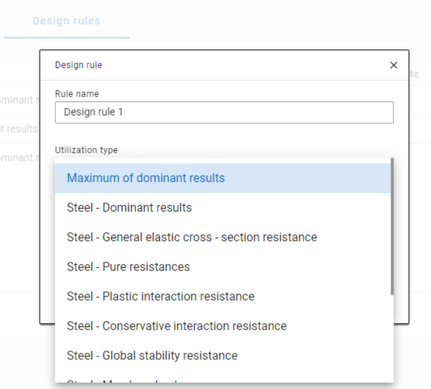
Design rule dialog in Consteel 16

The meaning of the dominant check

The dominant check is not always the check which gives the maximal ratio but the one with the maximum RELEVANT ratio. Typical example: if plastic interaction formulas are valid, those results will be dominant over general elastic cross-section check results, although the latter are higher.

Steel – Dominant results

Steel – Dominant results option contains the utility ratio of the dominant check at every finite element node, in all load combinations. Meaning that there are as many utilization values as the number of load combinations calculated, in every FE node.

It is also important to understand the difference between the utilizations of Maximum of dominant results and Steel -Dominant results. Maximum of dominant results option contains the dominant utility ratio of the dominant load combination at every node, like an envelope of Steel-Dominant results. Meaning there is only one utilization value in every FE node. Also, it is the same as the dominant result table on Global checks tab.

When a rule is applied, the utilizations of the chosen utilization type are compared against the limitation. The load combinations which give the results that correspond to the limitation, are selected by the rule. Every FE node of the selected model portion is examined.

Limitations in case of Steel – Dominant results

Let’s see an example of a simple 2D frame for better explanation. Right-side beam is in the portion for which three design rules were applied. Five points are selected for representation but of course all the nodes of the portion are examined against the rules’ limitations.
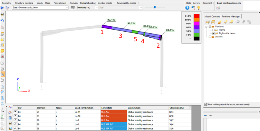
2D frame example with the designated FE nodes

The utilizations of the five dedicated FE node in all 11 load combinations are shown on the below diagram. (To find all of these utilizations in the attached model, global checks must be calculated for the load combinations one-by-one.)

gate

Consteel offers a range of load combination filtering options, which can be applied based on limit states, load cases, and analysis and design results. By applying different series of filters, designers can streamline their workflow and reduce calculation time.

Filtering options

Filtering is realized through the Load combination set definition window.
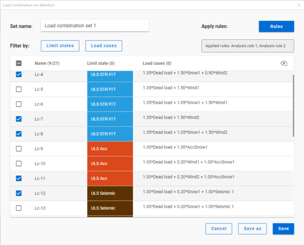
Filtering by limit states and by load cases are handled together with the checkboxes under the Limit states and Load cases buttons.
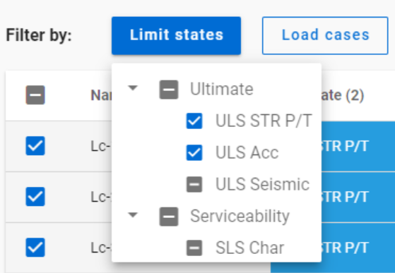
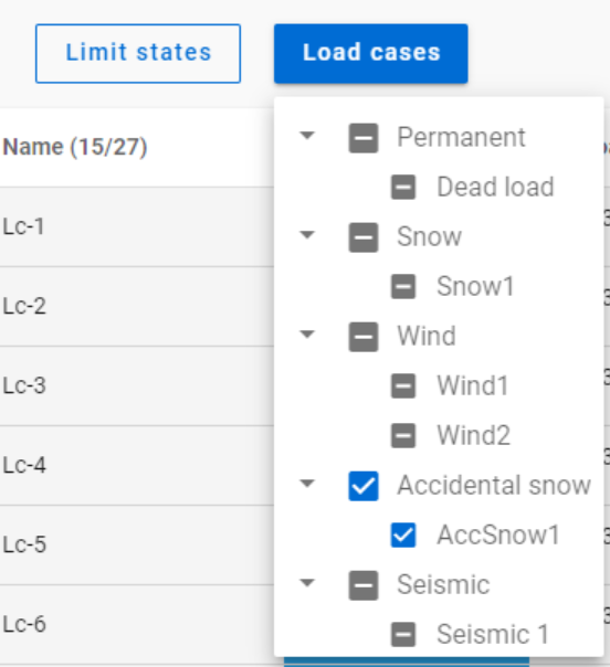
The 3-state checkboxes affect each other as they are not only used for selection but also for indication of the content. They can be manually set only to checked or unchecked. The middle state only appears when other filters are applied.

Filtering by limit states or load cases does not require any calculation results.

Filter by rules, on the other hand,is based on the actual analysis and/or design results. Different types of rules can be applied one by one or at the same time to select the desired load combinations.

When a rule is applied, all the load combinations that are selected on the Load combination set definition dialog- either with filtering by limit states/load cases or checked in manually- are examined at every position the rule indicates. Load combinations that meet the rule’s criteria are selected (remain checked in), while those that do not, become unchecked.

Interaction of the different filter types

Filtering by limit states, load cases, and rules can be used together, with rules being applied only to load combinations that are checked in and have the necessary calculation results.
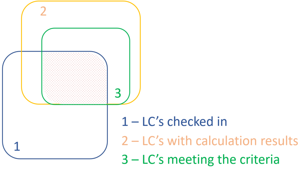
Let’s see an example.

It is a simple 2D frame model, with 27 load combinations of various limit states generated. Analysis and design results are calculated for all load combinations.
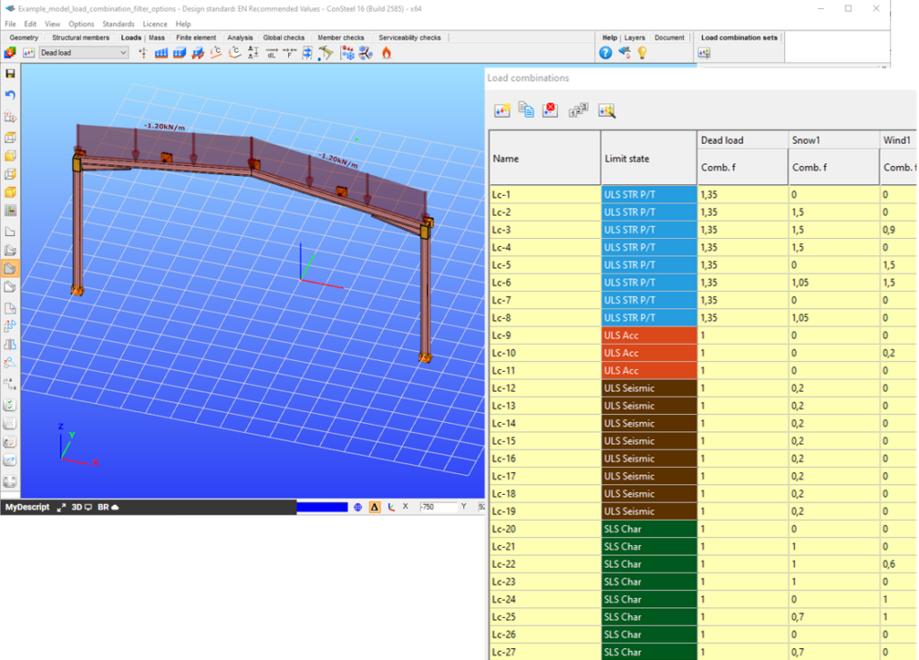
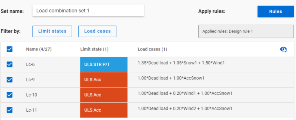
If applying design rule to select only those load combinations which result dominant utilization over 50%,

4 load combinations will be selected (Load combination set 1):
But if ULS Accidental limit state is turned off before applying the same 50% filter,  
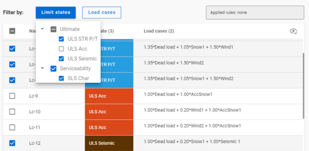
only one load combination is selected (see Load combination set 2).

Application of multiple rules

Applying multiple rules together results in the sum of the lists that would have been created separately.

gate

In Consteel 16, we introduced the function of load combination filter. Filtering is possible based on the load combinations’ limit state, load cases, and corresponding analysis and design results. The goal is to create different sets for the different steps of the optimization and reduce calculation time while making sure that all the relevant load combinations are considered. Let’s see what a conscious design workflow looks like in practice!

Description

It is a significant problem in almost all structural design projects that the standards define many possible load cases and combinations to evaluate. Although most of these load combinations are never relevant or provide decisive design situations, it is usually not evident which ones might be neglected safely, especially when considering, that different load combinations can be relevant for different parts of the structure, like primary or secondary structure, connections, etc. Accordingly, the optimization process is overloaded by a large amount of unnecessary calculations.

With the load combination filter function, a reduced list of load combinations aka a load combination set can be created and saved for the different steps of the optimization.

The optimal workflow for the filter may vary for the different purposes the sets are created for, but there is a recommended general process that can serve as the basis for all of them. First, run the simplest calculations and use the results for a rough selection which will already decrease the number of load combinations noticeably.  Then one can increase the complexity of the calculations and further reduce the list of combinations by using stricter filters. If needed, this step can be repeated. This iterative process allows us to avoid complex and time-consuming calculations for all the thousands of load combinations.
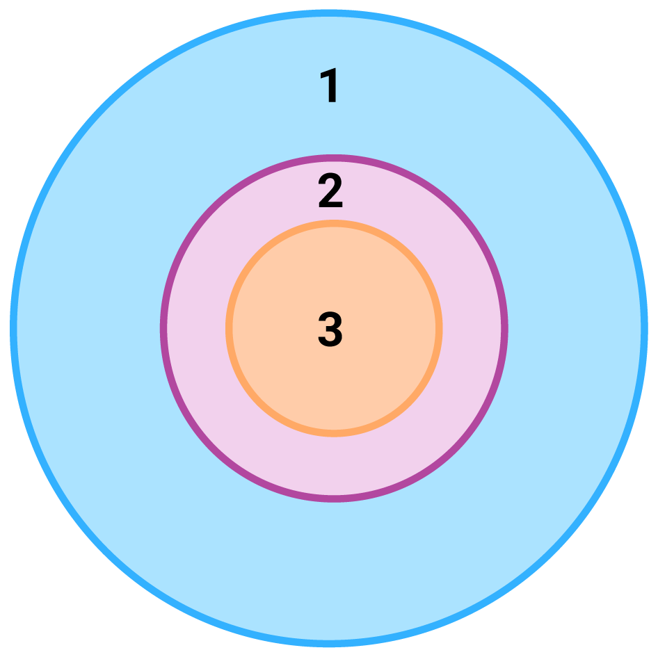
load combination amount with and without filtering

1 – all load combination, no filter;
2 – initial set with broad filter;
3 – working set with strict filter

Detailed process

Modeling

The base of all optimization processes is a correctly built structural model. So, the first step is geometrical and structural modeling and load definition. It is advisable to run a first-order analysis for only one or two load cases and diagnostics to find possible modeling errors. Load combinations can be created after that. Every limit state that will be used during the whole design of the structure, should be defined. Consteel’s automatic load combination generation function is an efficient tool to do it.

Calculation and filter

On the Load combination set definition dialog, it is possible to create load combination sets by selecting the combinations based on their limit state and/or the load cases they contain. But usually, filtering on specific analysis or design results will likely be more effective in reducing the number of combinations. Using the above-described general workflow, the steps are as follows:

gate