Did you know that you could use Consteel to draw a user-defined cross section and calculate its section properties?
In our previous article, we showed how predefined macro geometries make modelling fast and efficient. Later, we demonstrated how Consteel evaluates local and distortional buckling according to EN 1993-1-3.
This article focuses on the most flexible solution within this workflow: creating your own cross-section from scratch using the Section drafter module.
For line member modelling, the cross-section must first be loaded into the model. Besides using standard library profiles or macro sections, you can also choose the Draw Section option. This function is especially useful when a special geometry is required that cannot be reproduced with predefined macros, for example manufacturer-specific shapes, research sections, welded thin-walled members, or prototype geometries.
The Section drafter can be started from the Section Administration dialog by pressing the Draw section button. After launching the function, you need to select the section type, material quality and assign a name.
Two types of cross-sections are available: Cold formed section and General thin-walled section. This selection is not only geometric but also analytical.
Cold-formed sections are drawn with a single reference line and uniform thickness. During the calculation, Consteel automatically considers distortional buckling effects according to EN 1993-1-3. These sections can later be used in purlin line objects if they are defined as Z- or C-like shapes.
General thin-walled sections allow different thicknesses along the contour and closed geometries. They are typically used for welded or fabricated sheet sections. In this case, strength, local and global stability checks are available, but distortional buckling evaluation is not included.
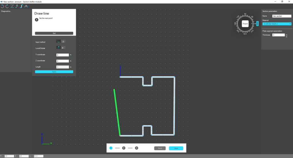
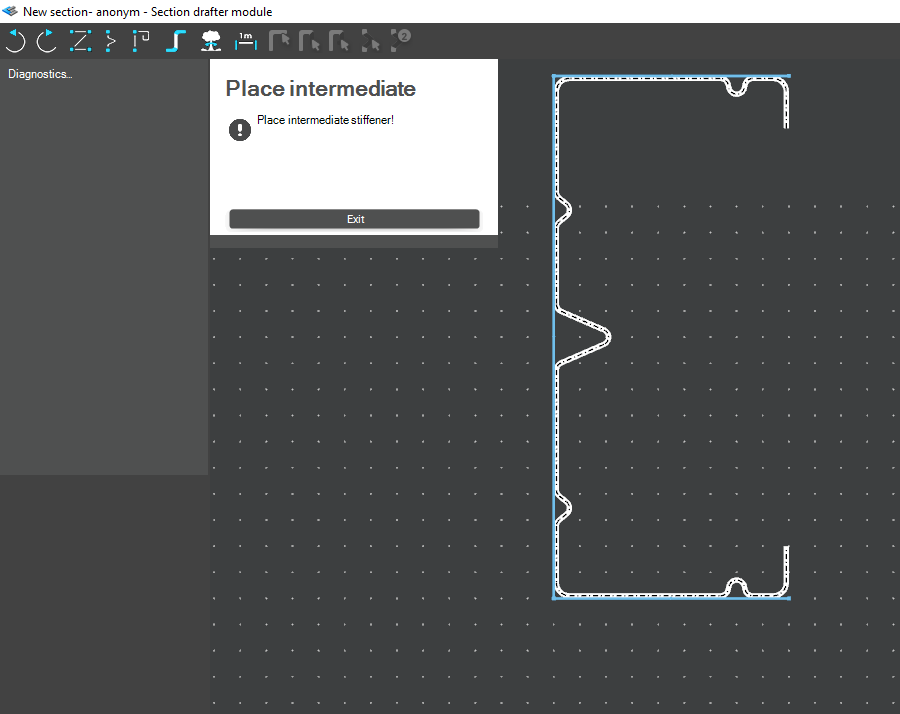
The drawing environment provides full control over geometry. Plate segments can be defined by coordinate input or by graphical selection. Cartesian or polar coordinates can be used, in local or global systems. Roundings are generated automatically between segments and can be modified later. The nominal thickness is also specified at this stage.
For cold-formed sections, stiffeners can be inserted using predefined macros, making it easier to model edge or intermediate stiffeners. However, these become structurally effective only after they are properly defined in the final phase of the section creation process.
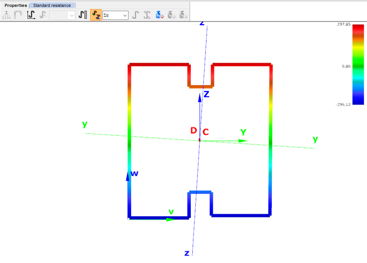
Once the geometry is complete, the required design parameters must be specified. For cold-formed sections, this includes the manufacturing type, thickness tolerance category and buckling curves. These inputs influence the calculated design wall thickness and stability verification. In the next step, the program evaluates the classification of each plate segment and determines the effective widths used in resistance calculations.
If stiffeners are present, they must be defined explicitly. When the section is identified as Z- or C-like, Consteel can automatically determine the critical stress of the stiffeners in accordance with EN 1993-1-3. This ensures that distortional buckling and stiffener interaction are properly considered during design.
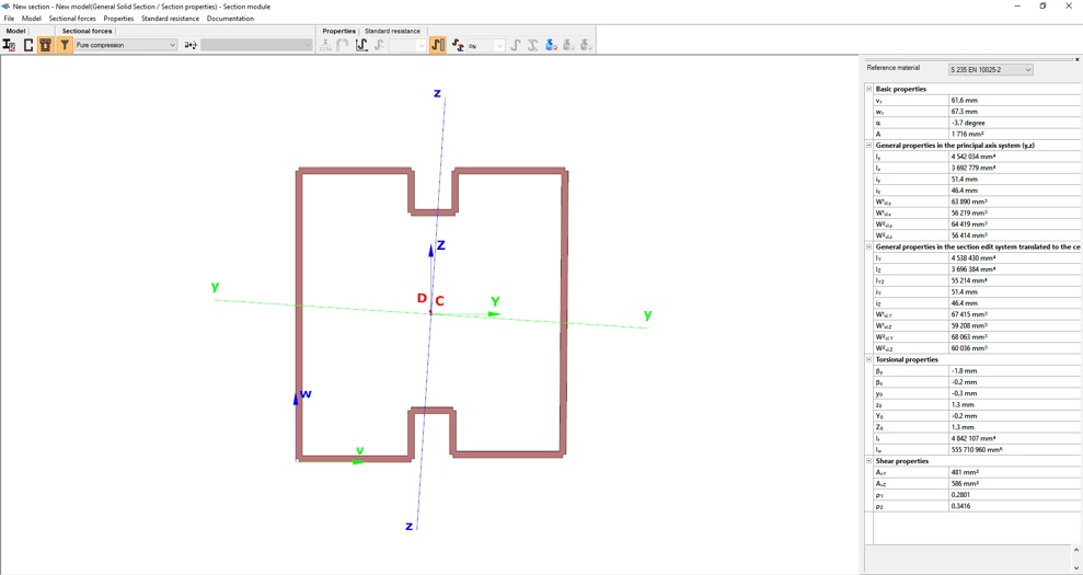
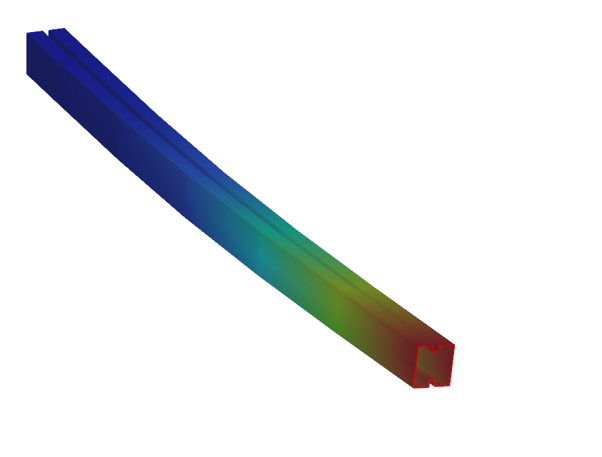
After saving the section, it can be assigned to line members just like any library or macro profile. Following structural analysis, steel design checks can be performed. As shown in our article on buckling checks, the Section module allows detailed review of effective cross-sectional properties, reduction factors, slenderness values and stiffener behaviour. Consteel automatically accounts for distortional buckling when the supplementary rules of EN 1993-1-3 are enabled.
By combining library, macro, and user-defined sections, Consteel provides a complete workflow: fast modelling with macros, precise verification through buckling checks, and full flexibility with custom cross-sections.
Download the example model and try it!
Download modelIf you haven’t tried Consteel yet, request a trial for free!
Try Consteel for freeDid you know that you could use Consteel to include in your model a wide range of cold-formed macro sections?
For line member modelling, the cross-section must first be loaded into the model. In Consteel, there are four options to do this, either starting from the Section Administrator or directly during beam or column modelling: From Library, Macro Section, Draw Section, or My Library.
Cold-formed sections can be created using any of these four methods. Standard cold-formed cross-sections can simply be selected from the library. However, if a special cold-formed section is needed, it can be created via Macro Sections, including: RHS, CHS, L profile, Z shape, C shape, Sigma section, Zeta section, Hat section with stiffeners, double C section, double Sigma section, and double user-defined sections.
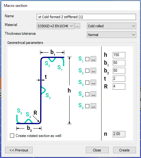
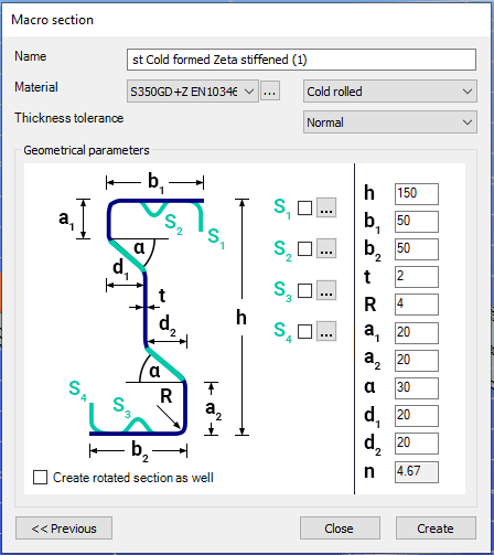
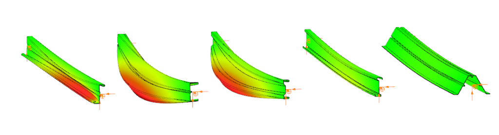
Macro sections are easy to create because the essential geometric characteristics are predefined, and the parameters can be modified intuitively. It is also possible to add profile stiffeners. Flange and web stiffeners can be configured in various forms, including single and double options. These defined stiffeners are included in the structural evaluation of distortional buckling, according to EN 1993-1-3.
The thickness tolerance category must be specified. This determines the design wall thickness for the section. In practice, macros follow the commonly applied tolerance categories used for coated steel sheet products.
If you want to use a double section, make sure to load into the model first the section that you want to duplicate.
For very special or unique sections, the Draw Section function can be used. This allows users to create fully custom cross-sections when standard or macro shapes are insufficient, by manually sketching the geometry.
Sections can be defined as cold-formed or general thin-walled, which determines how they are analyzed: cold-formed sections have uniform thickness and account for distortional buckling, while general thin-walled sections allow varied thicknesses and closed shapes, typically for welded or fabricated profiles.
This approach is especially useful for modelling unique shapes, prototypes, or as-built sections, giving full control over every segment to accurately capture geometries that standard libraries or macros cannot reproduce.
Download the example model and try it!
Download modelIf you haven’t tried Consteel yet, request a trial for free!
Try Consteel for freeIntroduction
It is essential for the effective work of the design engineers to have a model which is easy to overview. In Consteel there are several functions to achieve that such as layers and portions, and also Member coloring by cross-section.
How it works
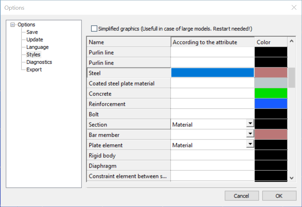
The color of the displayed objects is now determined by the object style settings in Options.
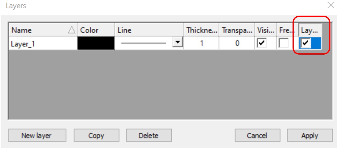
Layer color can overwrite these settings if the Layer style cell is checked on Layers dialog.
In the case of beam type members, it is also possible to set the color of the object according to the section it has defined. Coloring by member can be set with Object color setting dialog in the right bottom corner:
gate