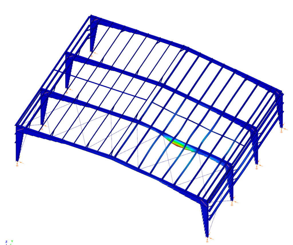
Consteel recommends to use the General Method from EN 1993-1-1 for the evaluation of out-of-plane strength of members and sturctures. In addition, the scaled imperfection based 2nd order approach is available.
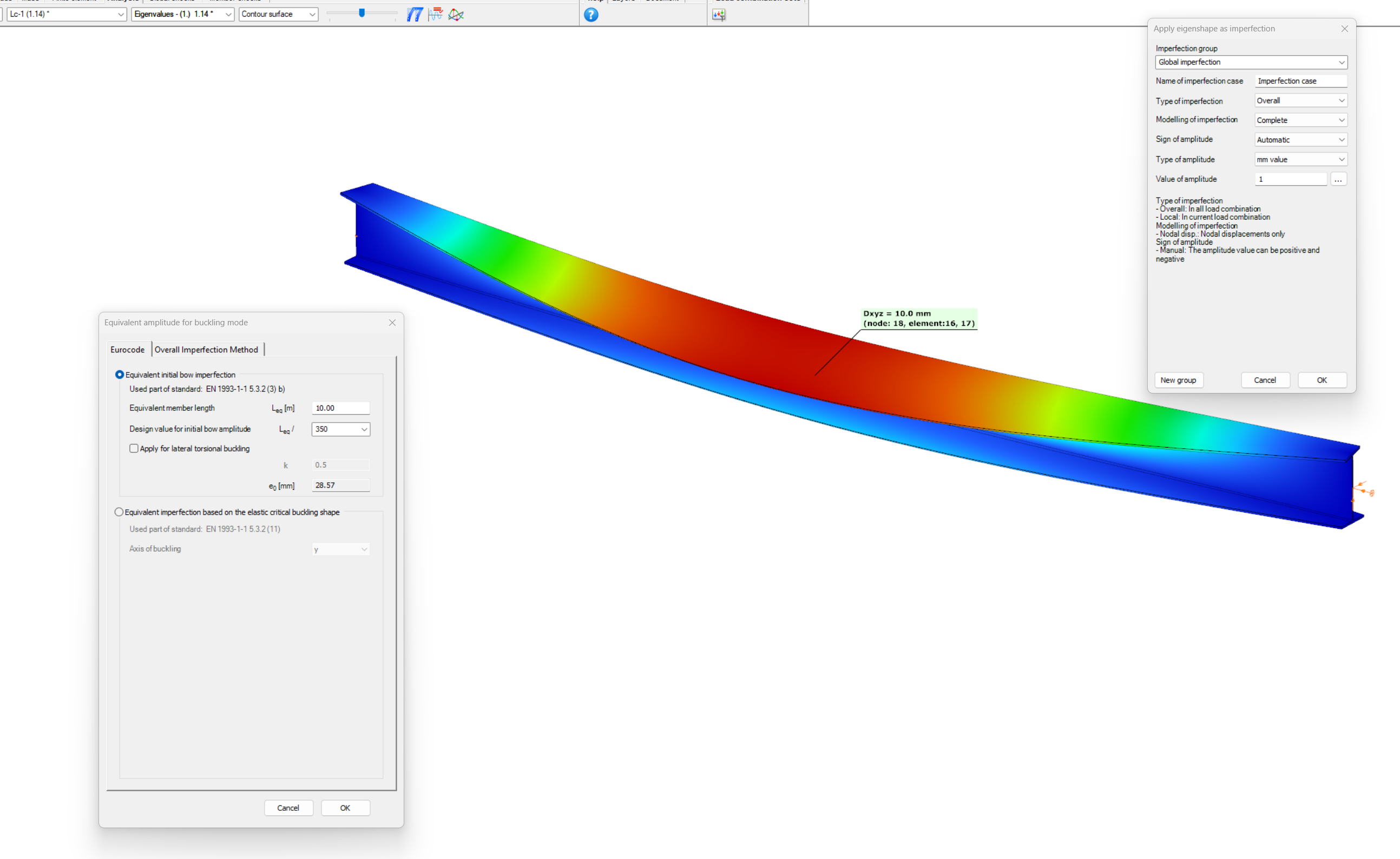
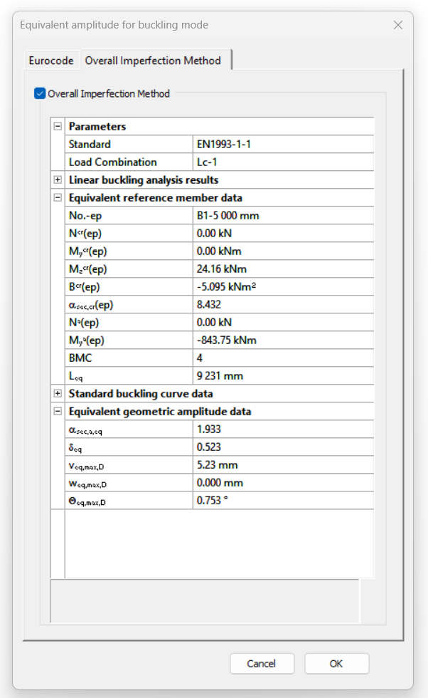
Did you know, that when linear buckling eigenform affine imperfections are used, Consteel can scale automatically the selected eigenmodes to perform a Eurocode compatible design? And you can even combine several imperfections?
Download the example model and try it!
Bending:
Download modelCopmression:
Download modelIf you haven’t tried Consteel yet, request a trial for free!
Try Consteel for free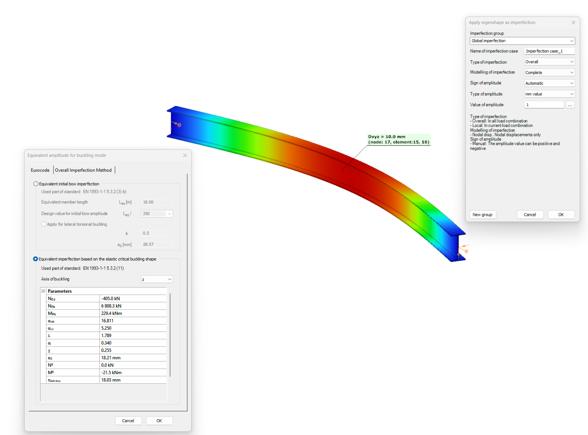
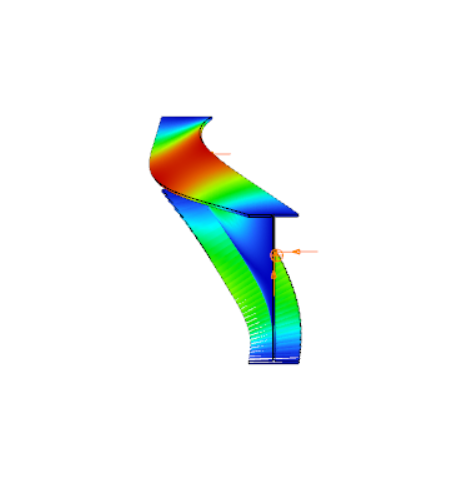
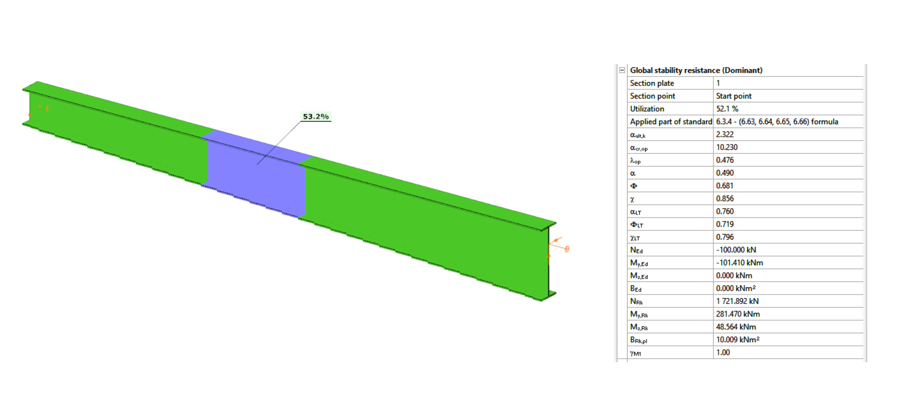
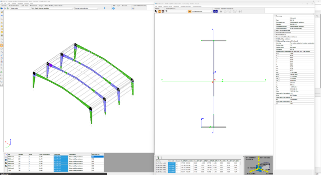
Have you ever heard about the ‘General Method’? This is an alternative design method to consider the interaction of axial compression with major-axis bending for general buckling situations, where the main interaction formulas are not applicable.
This basically includes every member with monosymmetric or asymmetric cross-sections or with cross-sections not uniform along the length (welded tapered sections) or laterally stabilized by sheeting or anything else without providing full fork supports.
Did you know, that the General Method is fully supported by Consteel and provides an automated buckling verification possibility? Of course, for the use of the General Method in a general case the traditional 12DOF beam finite elements are not applicable. But the special 14DOF beam elements used by Consteel are perfectly compatible?
Download the example model and try it!
Download modelIf you haven’t tried Consteel yet, request a trial for free!
Try Consteel for free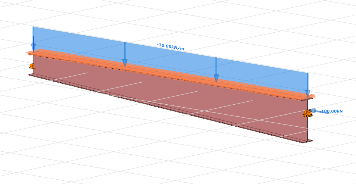
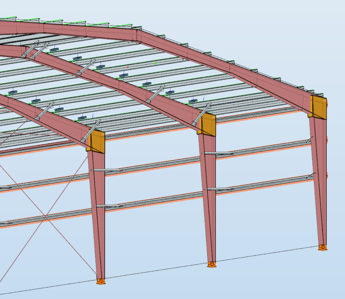
Did you know that you can use Consteel to design a pre-engineered Metal Building with all its unique characteristics, including web-tapered welded members, the interaction of primary and secondary structural elements, flange braces, shear and rotational stabilization effect provided by wall and roof sheeting?
Download the example model and try it!
Download modelIf you haven’t tried Consteel yet, request a trial for free!
Try Consteel for free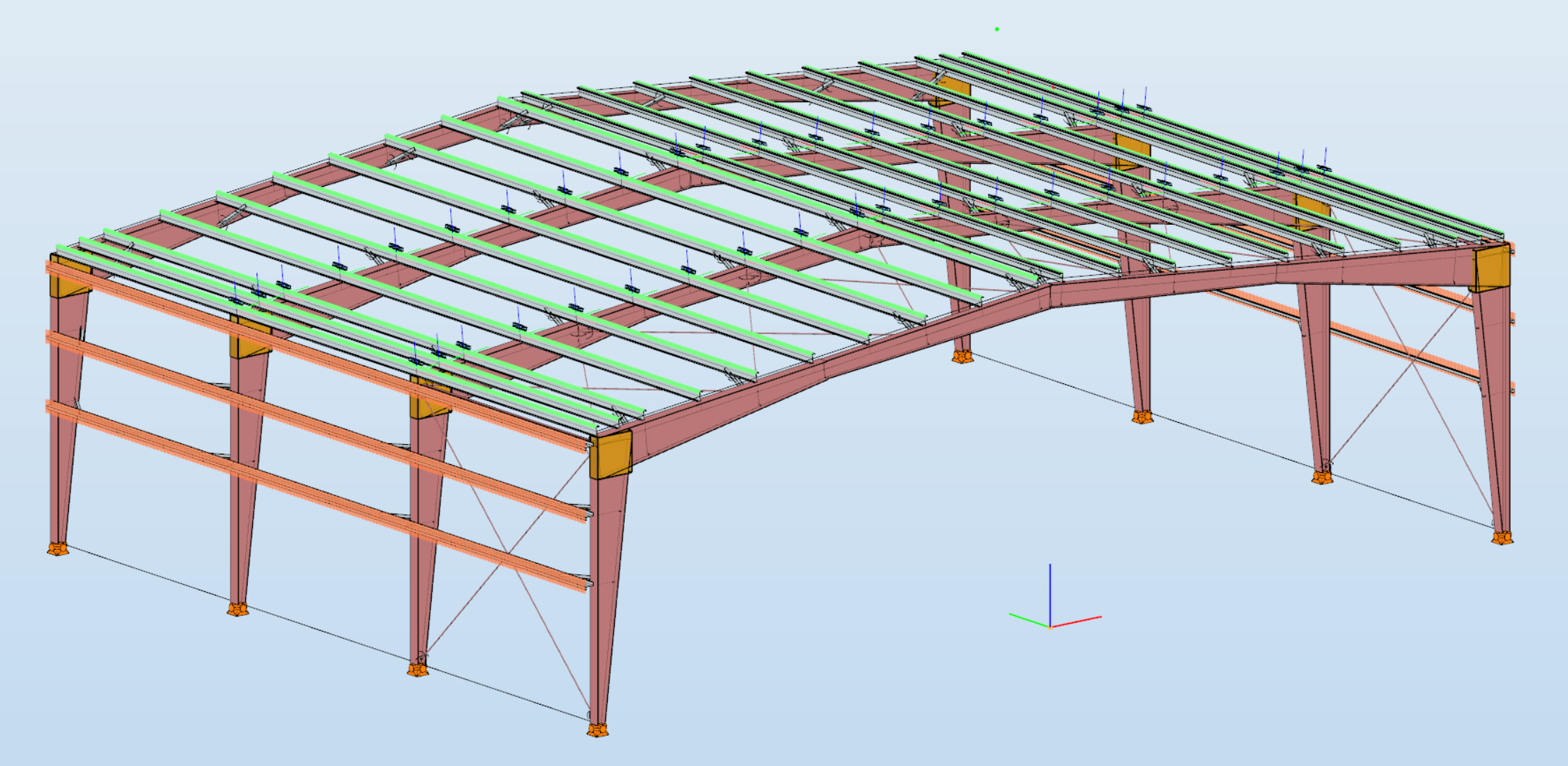
Introduction
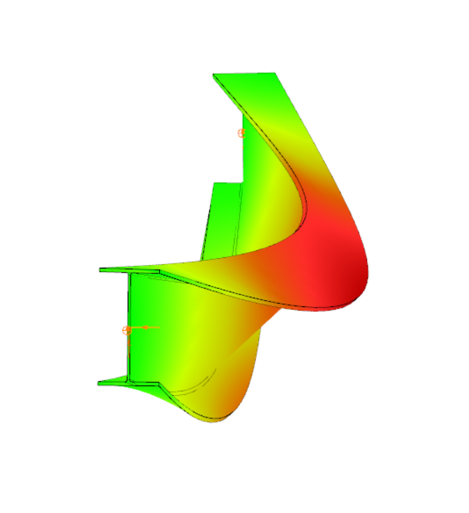
When a beam, bent in a plane, is allowed to move and twist freely between its two support points, in addition to bending, sudden perpendicular displacement and twisting may occur: causing the beam to deviate out of its original plane. This phenomenon is illustrated in Figure 1, showing a single supported beam with I-section bent around the strong axis. As the bending moment in the vertical plane increases, reaching a critical value, the beam undergoes abrupt lateral movement and twisting between the supports. This phenomenon is called lateral torsional buckling (LTB), which is a loss of stability mode that can apply to both perfect beams and real beams.

The design of the beam against LTB is fully analogous to the design of a compressed column against flexural buckling. The analogy is illustrated in Table 1, where the corresponding parameters are shown that affect the two buckling resistances:
| Flexural (column) buckling | Lateral torsional buckling |
|---|---|
| design force ($N_{Ed}$) | design moment ($M_{Ed}$) |
| critical force ($N_{cr}$) | critical moment ($M_{cr}$) |
| column slenderness ($\frac{}{\lambda}$) | beam slenderness ($\frac{}{\lambda}_{LT}$) |
| buckling reduction factor ($\chi$) | buckling reduction factor ($\chi_{LT}$) |
| buckling resistance ($N_{b,Rd}$) | buckling resistance ($M_{b,Rd}$) |
The critical moment of the perfect beam is determined at the location of the maximum value of the My,Ed design bending moment diagram. For a doubly symmetrical I cross-section:
$$M_{cr}=C_1\frac{\pi^2EI_z}{(k_z⋅L)^2}\left[\frac{I_\omega }{I_z}+ \frac{(k_zL)^2GI_t}{\pi^2EI_z}\right] ^{0.5} $$
where kz is the coefficient of restraint about the weak axis of the cross-section, G is the shear modulus, and It and Iω are the pure (St. Venant) and warping torsional moments of inertia of the cross-section. The value of the factor C1 depends on the shape of the bending moment diagram and its value can be found in appropriate tables and manuals. For a constant moment diagram, C1=1.0. The formula for the other design parameters, in particular the buckling reduction factor $\chi_{LT}$, depends on the design standard considered.
Lateral torsional buckling resistance by EN1993-1-1
The design of the beam against LTB (load capacity check) according to EC3-1-1 shall be carried out in the following steps:
gateIn Consteel, the calculation of cross sectional interaction resistance for Class 3 and 4 sections is executed with the modified Formula 6.2 of EN 1993-1-1 with the consideration of warping and altering signs of component resistances. Let’s see how…
Application of EN 1993-1-1 formula 6.2
For calculation of the resistance of a cross section subjected to combination of internal forces and bending moments, EN 1993-1-1 allows the usage -as a conservative approximation- a linear summation of the utilization ratios for each stress resultant, specified in formula 6.2.
$$\frac{N_{Ed}}{N_{Rd}}+\frac{M_{y,Ed}}{M_{y,Rd}}+\frac{M_{z,Ed}}{M_{z,Rd}}\leq 1$$
As Consteel uses the 7DOF finite element and so it is capable of calulcating bimoment, an extended form of the formula is used for interaction resistance calculation to consider the additional effect.
$$\frac{N_{Ed}}{N_{Rd}}+\frac{M_{y,Ed}}{M_{y,Rd}}+\frac{M_{z,Ed}}{M_{z,Rd}}+\frac{B_{Ed}}{B_{Rd}}\leq 1$$
Formula 6.2 ignores the fact that not every component results the highest stress at the same critical point of the cross-section.
In order to moderate this conservatism of the formula, Consteel applies a modified method for class 3 and 4 sections. Instead of calculating the maximal ratio for every force component using the minimal section moduli (W), Consteel finds the most critical point of the cross-section first (based on the sum of different normal stress components) and calculates the component ratios using the W values determined for this critical point. Summation is done with considering the sign of the stresses caused by the components corresponding to the sign of the dominant stress in the critical point.
(For class 1 and 2 sections, the complex plastic stress distribution cannot be determined by the software. The Formula 6.2 is used with the extension of bimoments to calculate interaction resistance, but no modification with altering signs is applied)
Example
Let’s see an example for better explanation.
GATEConsteel offers a range of load combination filtering options, which can be applied based on limit states, load cases, and analysis and design results. By applying different series of filters, designers can streamline their workflow and reduce calculation time.
Filtering options
Filtering is realized through the Load combination set definition window.
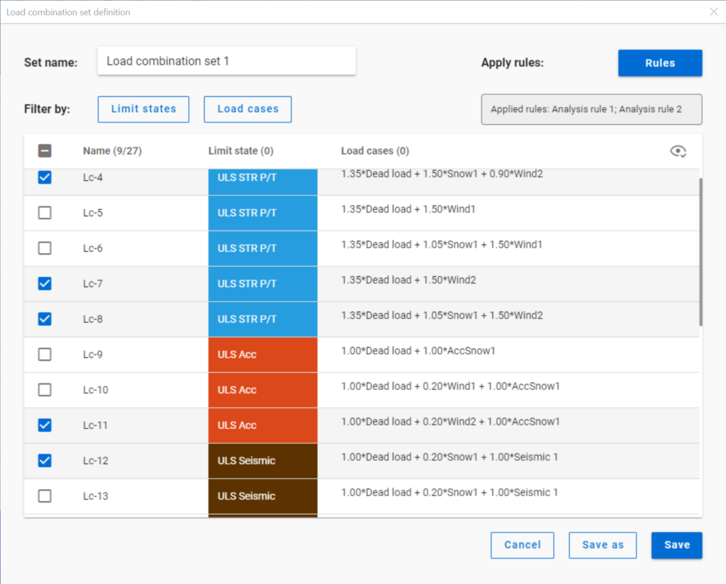
Filtering by limit states and by load cases are handled together with the checkboxes under the Limit states and Load cases buttons.
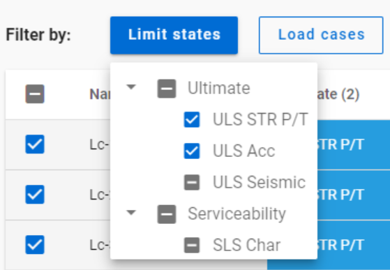
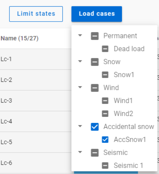
The 3-state checkboxes affect each other as they are not only used for selection but also for indication of the content. They can be manually set only to checked or unchecked. The middle state only appears when other filters are applied.
Filtering by limit states or load cases does not require any calculation results.
Filter by rules, on the other hand,is based on the actual analysis and/or design results. Different types of rules can be applied one by one or at the same time to select the desired load combinations.
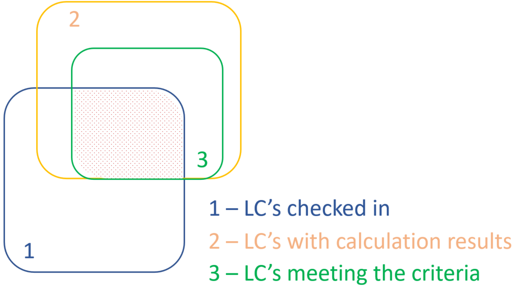
When a rule is applied, all the load combinations that are selected on the Load combination set definition dialog- either with filtering by limit states/load cases or checked in manually- are examined at every position the rule indicates. Load combinations that meet the rule’s criteria are selected (remain checked in), while those that do not, become unchecked.
- With analysis rules, load combinations can be selected based on deformations or internal forces at either every finite element node or only at the member ends. This last one is included specifically for connection design. Deformations are checked in SLS combinations, internal forces are checked in ULS combinations only.
- With buckling rules, those ULS load combinations can be selected which have the elastic critical load factor (first buckling eigenvalue) less than the given limit.
- With design rules, load combinations can be selected based on utility ratios checked in every finite element node of the chosen portion. Utilizations are available from several design checks: dominant results and detailed verifications for steel elements such as general elastic cross-section check, pure resistances, interactions and global stability. Only ULS combinations can be filtered with design rules.
Interaction of the different filter types
Filtering by limit states, load cases, and rules can be used together, with rules being applied only to load combinations that are checked in and have the necessary calculation results.
Let’s see an example.
It is a simple 2D frame model, with 27 load combinations of various limit states generated. Analysis and design results are calculated for all load combinations.
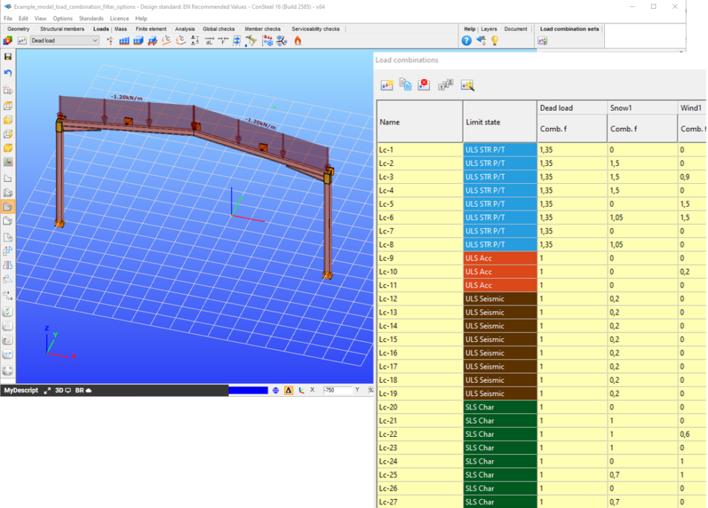
If applying design rule to select only those load combinations which result dominant utilization over 50%,

4 load combinations will be selected (Load combination set 1):
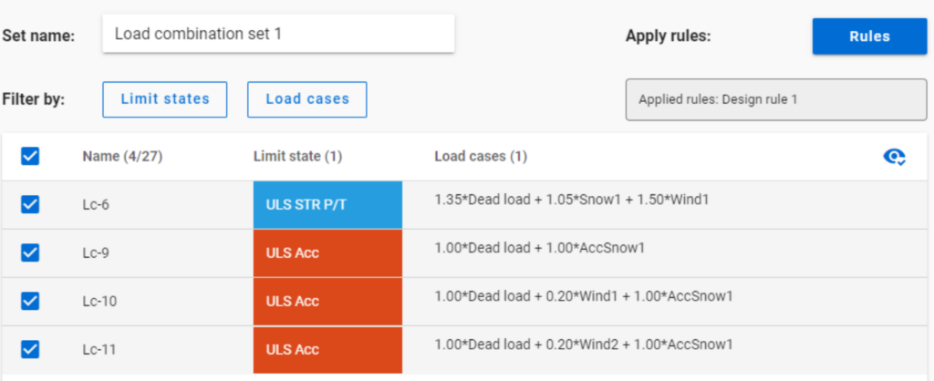
But if ULS Accidental limit state is turned off before applying the same 50% filter,
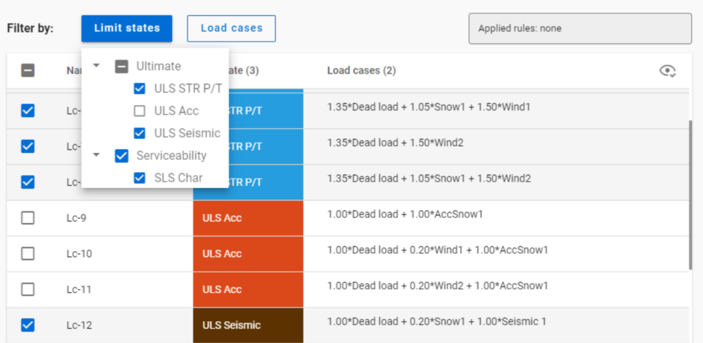
only one load combination is selected (see Load combination set 2).

Application of multiple rules
Applying multiple rules together results in the sum of the lists that would have been created separately.
gateThe practical use of the ‘General method’ of EN 1993-1-1 6.3.4 for the buckling design of global structural models is still a challenging issue requiring several problems to solve. In this paper we propose a fully developed methodology presenting solutions for the application topics such as the suitable FE model, specific modeling issues to capture the true 3D behavior of the members and the whole model and the final evaluation of the design parameters. The presented methodology consistently uses a unique model for the evaluation of all analysis and design parameters and results and yields a fully automatic design process controlled solely by the properly created structural model.
Click the button bellow to download and read the full article.
gate