In Consteel, the calculation of cross sectional interaction resistance for Class 3 and 4 sections is executed with the modified Formula 6.2 of EN 1993-1-1 with the consideration of warping and altering signs of component resistances. Let’s see how…
Application of EN 1993-1-1 formula 6.2
For calculation of the resistance of a cross section subjected to combination of internal forces and bending moments, EN 1993-1-1 allows the usage -as a conservative approximation- a linear summation of the utilization ratios for each stress resultant, specified in formula 6.2.
$$\frac{N_{Ed}}{N_{Rd}}+\frac{M_{y,Ed}}{M_{y,Rd}}+\frac{M_{z,Ed}}{M_{z,Rd}}\leq 1$$
As Consteel uses the 7DOF finite element and so it is capable of calulcating bimoment, an extended form of the formula is used for interaction resistance calculation to consider the additional effect.
$$\frac{N_{Ed}}{N_{Rd}}+\frac{M_{y,Ed}}{M_{y,Rd}}+\frac{M_{z,Ed}}{M_{z,Rd}}+\frac{B_{Ed}}{B_{Rd}}\leq 1$$
Formula 6.2 ignores the fact that not every component results the highest stress at the same critical point of the cross-section.
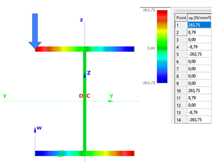
In order to moderate this conservatism of the formula, Consteel applies a modified method for class 3 and 4 sections. Instead of calculating the maximal ratio for every force component using the minimal section moduli (W), Consteel finds the most critical point of the cross-section first (based on the sum of different normal stress components) and calculates the component ratios using the W values determined for this critical point. Summation is done with considering the sign of the stresses caused by the components corresponding to the sign of the dominant stress in the critical point.
(For class 1 and 2 sections, the complex plastic stress distribution cannot be determined by the software. The Formula 6.2 is used with the extension of bimoments to calculate interaction resistance, but no modification with altering signs is applied)
Example
Let’s see an example for better explanation.
GATEDid you know that you could use Consteel to perform dual analysis with 7DOF beam and/or shell elements?
With two advanced features, Superbeam and Convert members to plates, you can choose the approach that best suits your project needs, whether you’re focused on modeling efficiency or detailed analysis.
The Superbeam function offers a smart, adaptive way to handle structural members. It enables you to model with the simplicity of standard 7DOF beam elements while allowing you to switch to a more detailed shell-based analysis for specific members whenever needed.
Once the structure is modeled using beam elements, you can select how each member is analyzed:
- Using the beam model, which applies Consteel’s proven 7DOF beam elements along with its comprehensive design tools.
- Or using a shell model, which is automatically generated for selected members. This shell model includes detailing features such as web cutouts and stiffeners, fully integrated into the global analysis model.
This dual approach is fully adaptive. You can continue modifying your model using beam elements and switch between analysis modes as required, offering both speed and precision within the same workflow.
For a complete overview of how to activate and manage Superbeam functionality, refer to the documentation:
Superbeam – Consteel Manual

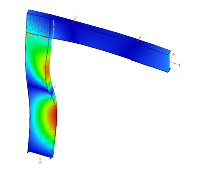

When you need complete control over geometry and mesh, or when shell analysis alone is not sufficient, Consteel provides the Convert members to plates function. This tool allows you to manually transform selected members into actual plate elements, enabling detailed modeling from the start.
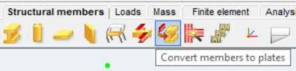
Unlike the automatic conversion used in Superbeam, this method performs a permanent, non-reversible transformation (though undo is available during the session). It supports a wide range of section types, including hot-rolled, cold-formed, and welded profiles.
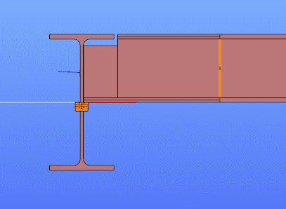
The conversion process preserves and adapts existing connections, eccentricities, loads, and supports. Where needed, rigid bodies and constraint elements are added to maintain structural continuity. These constraints ensure proper transfer of deformations, including warping, between the new plate model and the rest of the structure.
This function is especially useful in cases where precision is critical, such as modeling joints, fabrication-specific details, or complex load interactions.
To learn more, see the full guide here:
Convert Members to Plates – Consteel Manual
Both Superbeam and Convert members to plates serve different purposes, depending on the level of detail and control required in your model:
| Feature | Superbeam | Convert members to plates |
| Workflow | Beam modeling with optional shell analysis | Full plate modeling from the beginning |
| Conversion | Automatic and reversible | Manual and permanent |
| Suitable For | Flexibility in analysis, quick modeling | Full control, high-detail requirements |
| Supported Sections | Welded I and H profiles | Hot-rolled, cold-formed, and welded sections |
| Detailing Support | Cutouts and stiffeners (in shell analysis) | Full geometric detailing, including transitions |
| Design Integration | Integrated with beam-based design tools | Suitable for fabrication-level modeling |
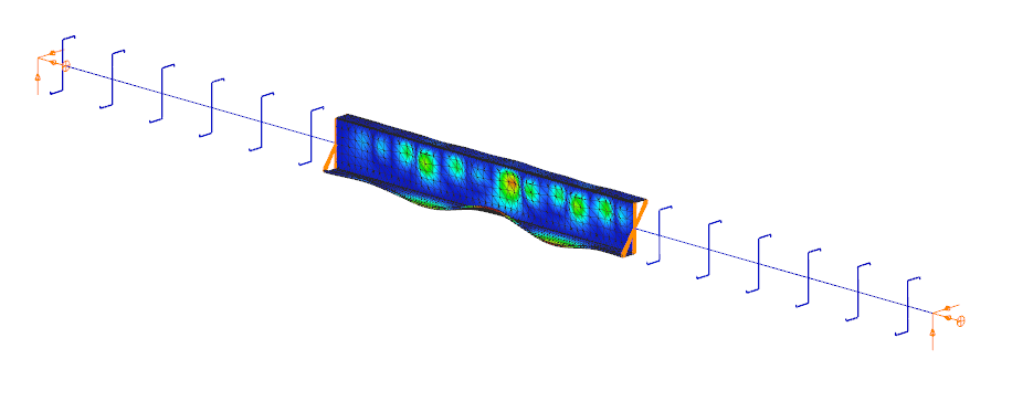
In Superbeam, constraint elements are generated automatically to connect converted shell elements to other members, such as bars. During member-to-shell conversion, these elements link the FE shell nodes to the rest of the model, ensuring accurate deformation transfer.
If the convert members to plate function is applied directly to beam elements, rigid bodies are created at their ends, which is useful for analyzing local behavior but does not transfer warping deformations. If the beam is first converted to a shell and then to plates, hinged rigid edges are placed along the plate boundaries. This arrangement, combined with constraint elements, transfers not only in-plane and out-of-plane deformations but also warping between the shell and the rest of the structure.
Download the example model and try it!
Download modelIf you haven’t tried Consteel yet, request a trial for free!
Try Consteel for freeDid you know that you could use Consteel to calculate effective cross-section properties for Class 4 sections?
The classification of cross-sections is used to understand how local buckling affects the strength and rotation capacity of structural members. As stated in Eurocode 3 (EN 1993-3-3, Section 5.5), this classification helps determine whether a cross-section can reach its full resistance or if its behavior is limited by local instability.
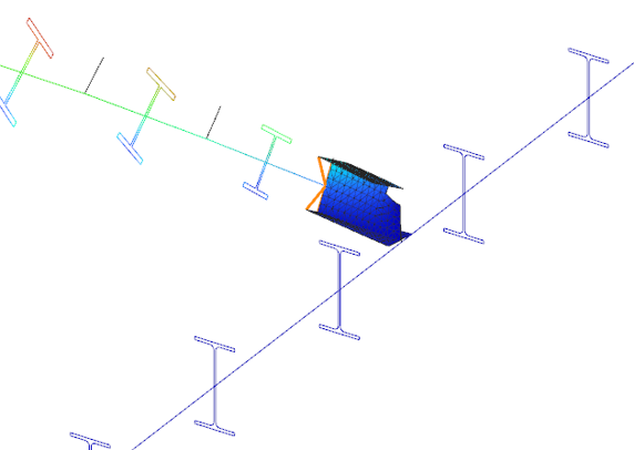
Class 4 cross-sections are those in which local buckling occurs before the material reaches the yield stress in one or more parts. Because of this, their resistance must be calculated using effective section properties that take into account the reduction caused by local buckling.
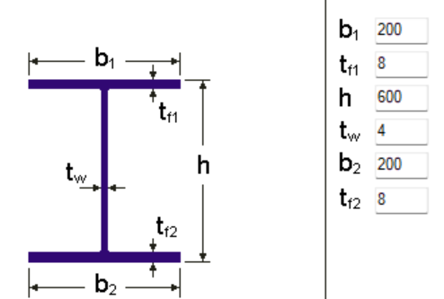
Typical Class 4 sections are characterized by slender elements with high width-to-thickness ratios. These commonly include thin webs or flanges, hollow sections (RHS/CHS) with slender walls, thin-walled cold-formed profiles such as C- or L-sections, and welded I-sections with slender webs. In this example, we consider a welded I-section with the following geometric parameters:
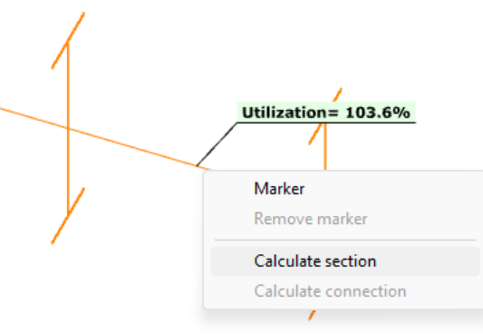
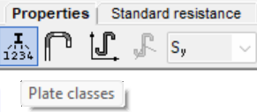
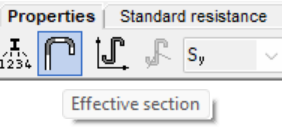
In Consteel, we can then see the section classification from the Global Checks tab. After selecting the investigated section either in the model or from the table and clicking on the Calculate Section option, and then choosing the Plate Classes in the Properties tab.
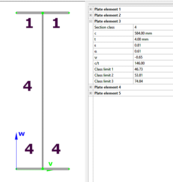
The effective section properties can then be viewed using the second option in the Properties tab.
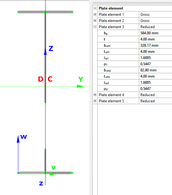
In addition, stresses can be visualized by clicking on the Stresses icon. They can be represented either as a colored figure or as a 3D diagram.
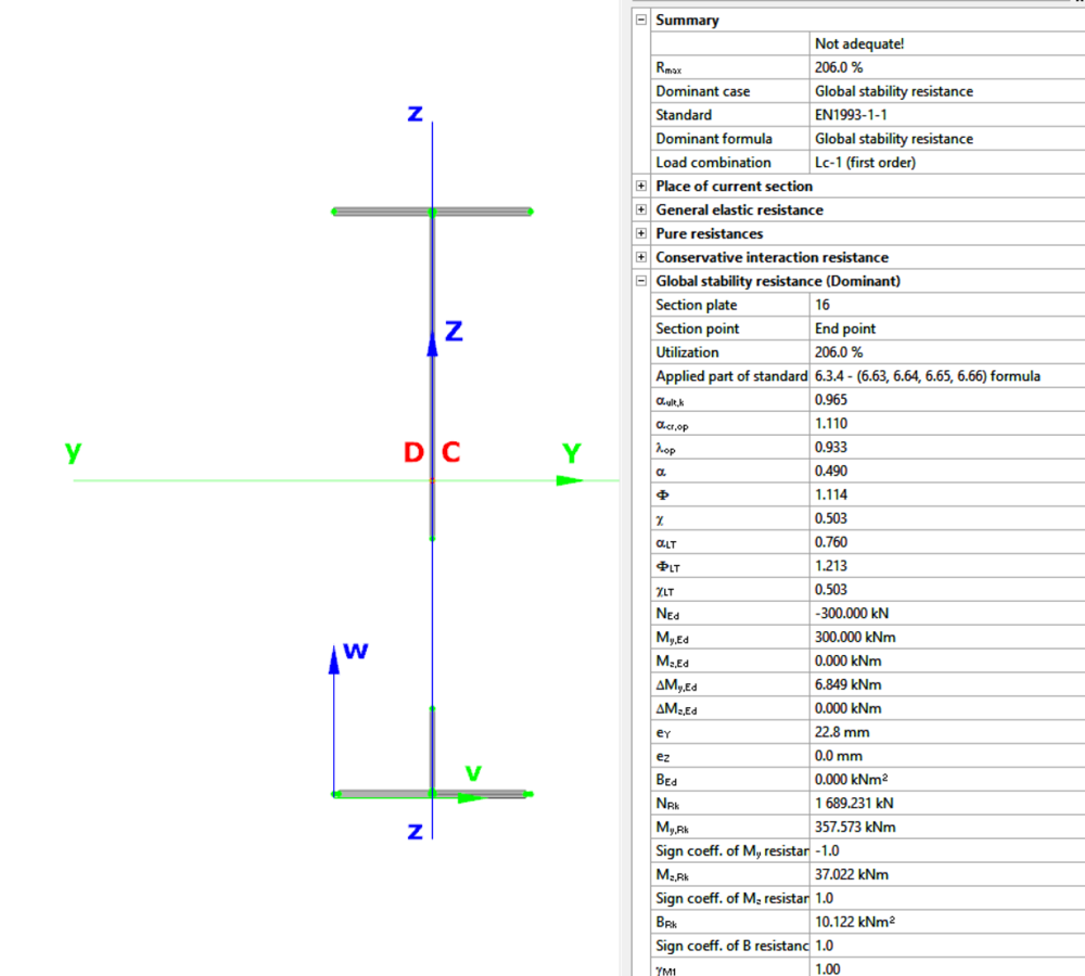
For Class 4 sections, the Standard Resistance tab in the section module provides a complete assessment for the selected loading case.
The section module performs all necessary calculations according to the Eurocode (EN 1993-1-1 and relevant parts of EN 1993-1-5), including general elastic resistance, pure case resistance, conservative interaction checks, and web buckling analysis.
All resistances are calculated using the effective section properties to account for local buckling, and the module identifies the dominant case to ensure all relevant checks are covered.
Download the example model and try it!
Download modelIf you haven’t tried Consteel yet, request a trial for free!
Try Consteel for freeIntroduction
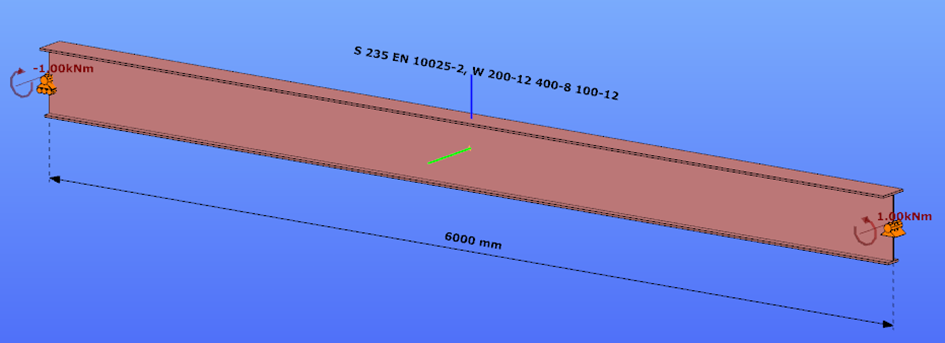
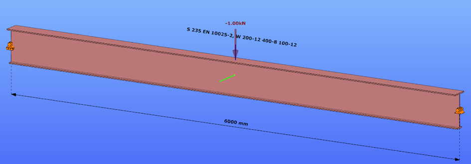
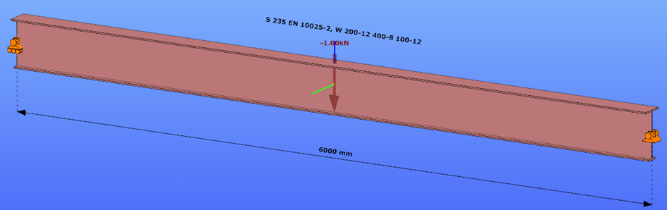
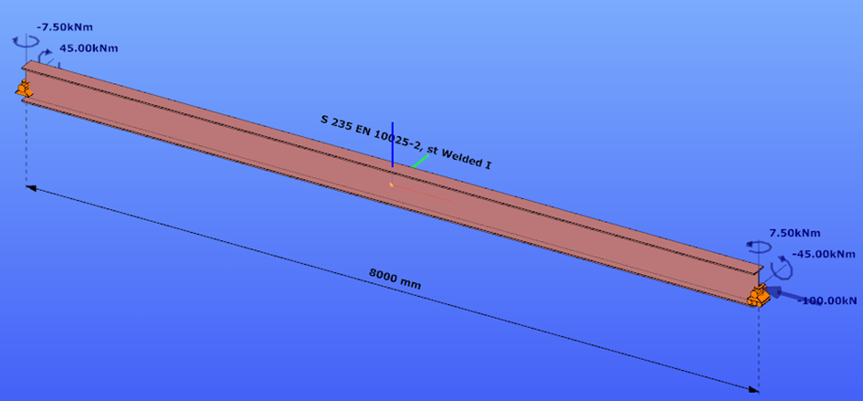
This verification example studies a simple fork supported beam member with welded section (flanges: 200-12 and 100-12; web: 400-8) subjected to bending about major axis. Constant bending moment due to concentrated end moments and triangular moment distribution from concentrated transverse force is examined for both orientations of the I-section. Critical moment and force of the member is calculated by hand and by the Consteel software using both 7 DOF beam finite element model and Superbeam function.
Geometry
Normal orientation – wide flange in compression
Constant bending moment distribution
Triangular bending moment distribution – load on upper flange
Triangular bending moment distribution – load on bottom flange
Reverse orientation – narrow flange in compression
Constant bending moment distribution
Triangular bending moment distribution – load on upper flange
Triangular bending moment distribution – load on bottom flange
Calculation by hand
Factors to be used for analitical approximation formulae of elastic critical moment are taken from G. Sedlacek, J. Naumes: Excerpt from the Background Document to EN 1993-1-1 Flexural buckling and lateral buckling on a common basis: Stability assessments according to Eurocode 3 CEN / TC250 / SC3 / N1639E – rev2
Normal orientation – wide flange in compression
Constant bending moment distribution
Reverse orientation – narrow flange in compression
Computation by Consteel
Version nr: Consteel 15 build 1722
Normal orientation – wide flange in compression
Constant bending moment distribution
- 7 DOF beam element
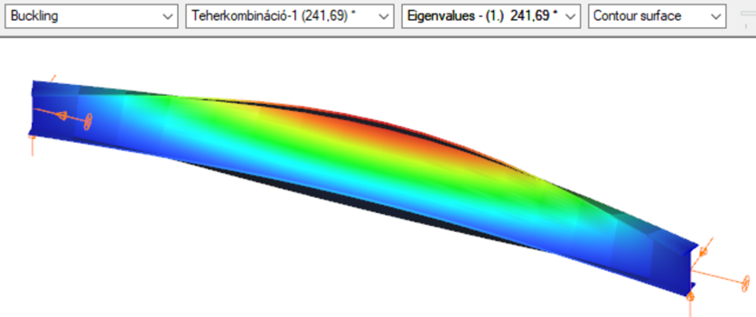
First buckling eigenvalue of the member which was computed by the Consteel software using the 7 DOF beam finite element model (n=25). The eigenshape shows lateral torsional buckling.
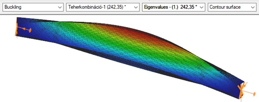
Superbeam
First buckling eigenvalue of the member which was computed by the Consteel software using the Superbeam function (δ=25).
Introduction
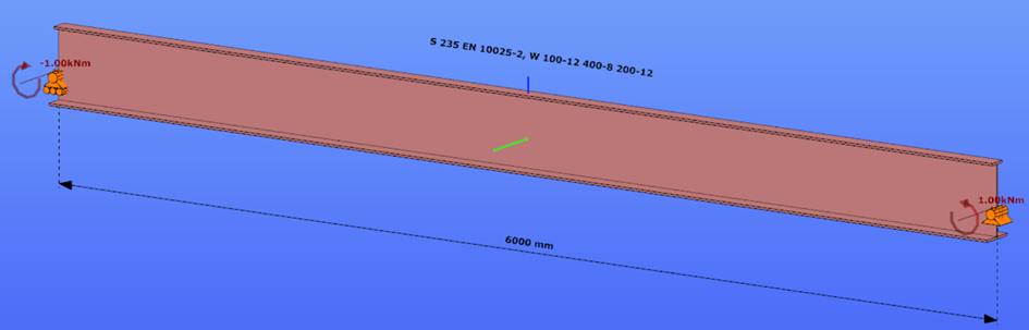
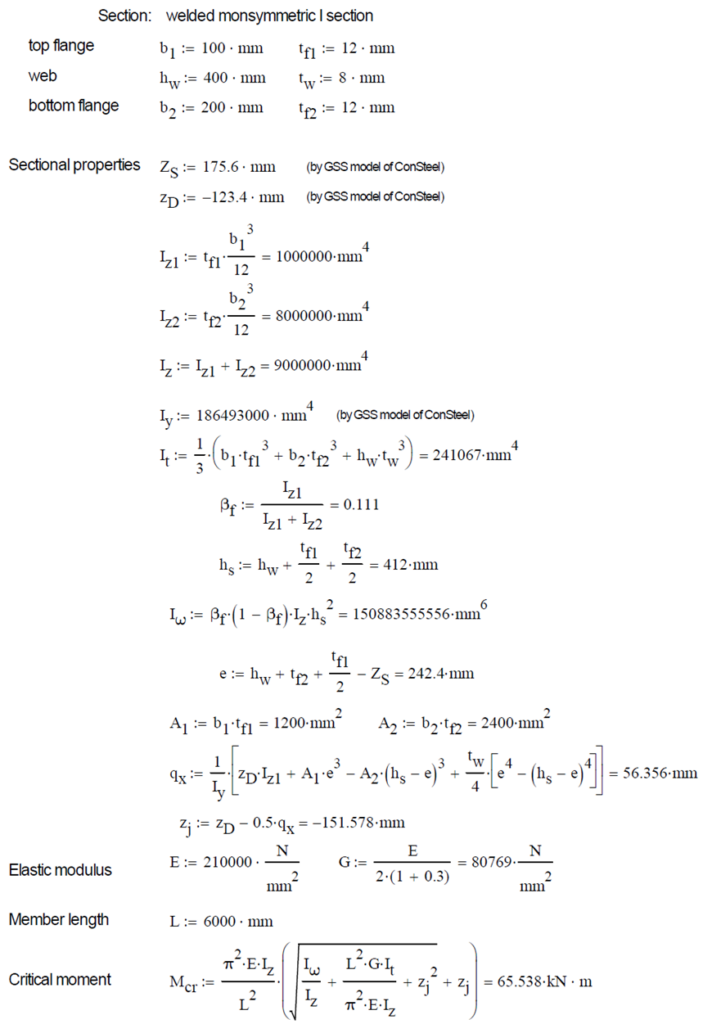
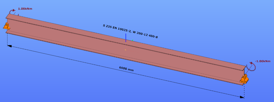
This verification example studies a simple fork supported beam member with welded section (flanges: 200-12; web: 400-8) subjected to bending about major axis. Constant bending moment due to concentrated end moments and triangular moment dsitribution from concentrated transverse force is examined. Critical moment and force of the member is calculated by hand and by the Consteel software using both 7 DOF beam finite element model and Superbeam function.
Geometry
Constant bending moment distribution
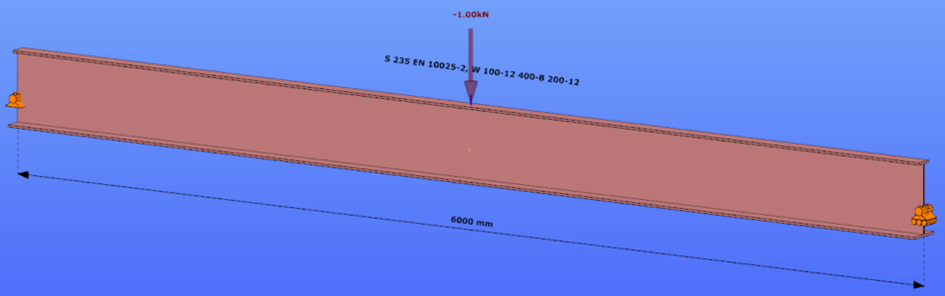
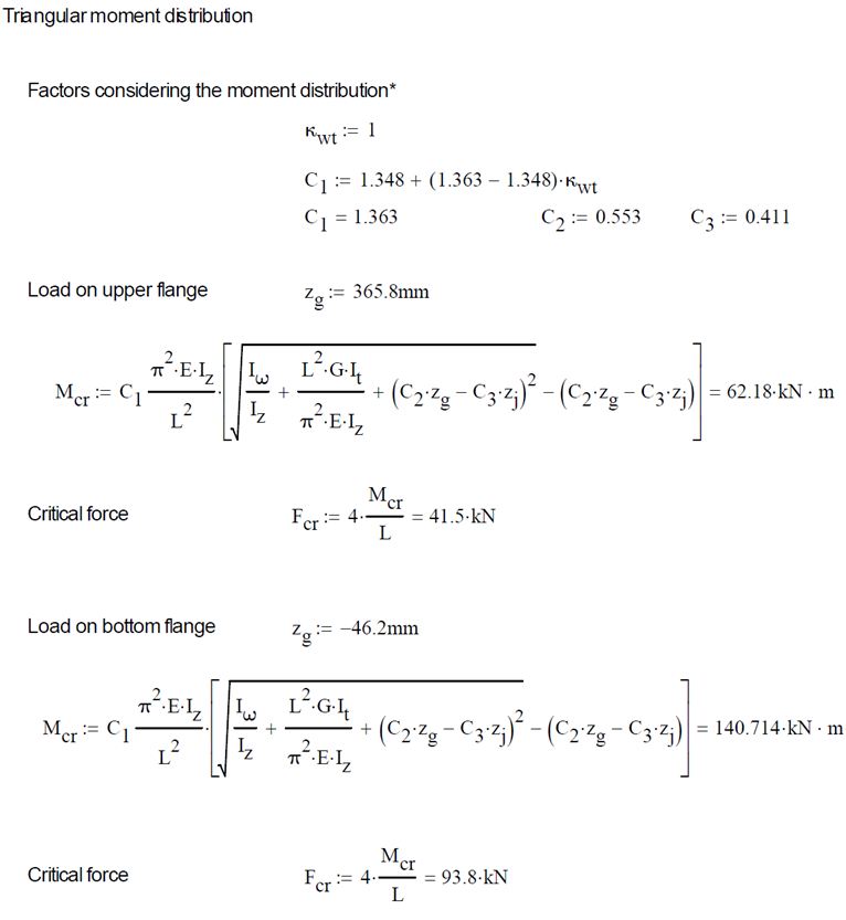
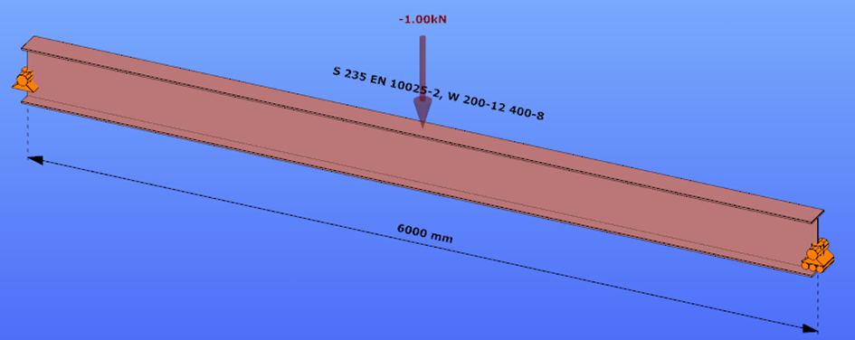
Triangular bending moment distribution – load on upper flange
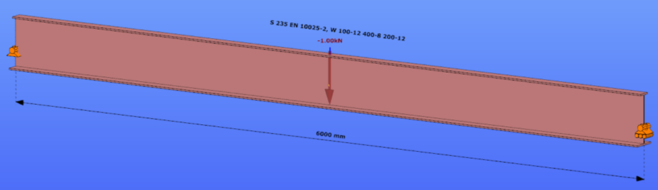
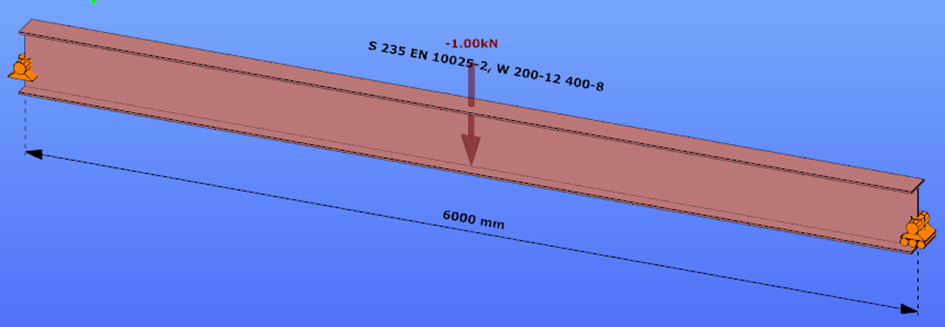
Triangular bending moment distribution – load on bottom flange
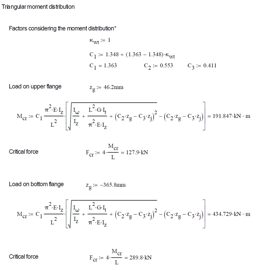
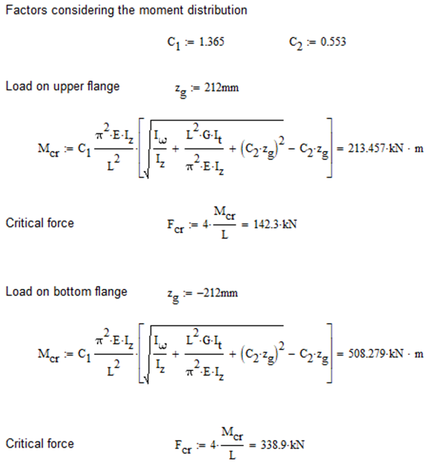
Calculation by hand
Constant bending moment distribution

Triangular bending moment distribution
Computation by Consteel
Version nr: Consteel 15 build 1722
Constant bending moment distribution
7 DOF beam element
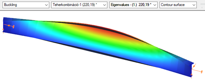
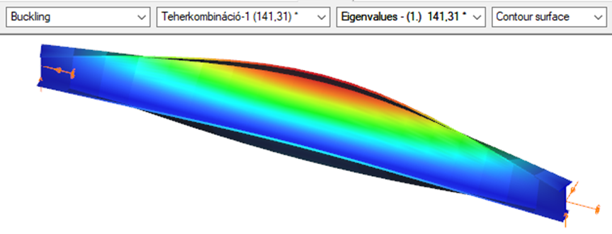
First buckling eigenvalue of the member which was computed by the Consteel software using the 7 DOF beam finite element model (n=16). The eigenshape shows lateral torsional buckling.
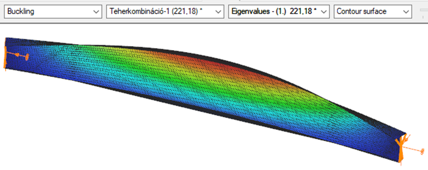
Superbeam
First buckling eigenvalue of the member which was computed by the Consteel software using the Superbeam function (δ=25).
Triangular bending moment distribution – load on upper flange
7 DOF beam element
First buckling eigenvalue of the member which was computed by the Consteel software using the 7 DOF beam finite element model (n=16).
Superbeam
First buckling eigenvalue of the member which was computed by the Consteel software using the Superbeam function (δ=25).

Triangular bending moment distribution – load on bottom flange
(more…)Introduction
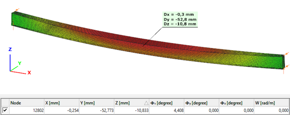
This verification example studies a simple fork supported beam member with welded section equivalent to IPE360 (flanges: 170-12,7; web: 347-8) subjected to biaxial bending due to concentrated end moments and compression due to axial force. Second order deformations of the middle cross-section of the member are calculated by hand and by the ConSteel software using both 7DOF beam and shell finite elements and Superbeam function. In addition to the verification, the difference between modelling with 6DOF and 7DOF elements is demonstrated.
Geometry
Calculation by hand
The first order and the simple amplified (P-δ) deformations can be analitically calculated by the well known formulas. The calculation of the second order deformations considering true, three-dimensional behaviour of the beam is however so complicated that there are only approximate analitical formulas available for hand calculation. The formula below can be found in Chen, W. and Atsuta, T.: Theory of Beam-Columns, Vol. 2: Space behavior and design, McGRAW-HILL 1977, p. 192

Computation by Consteel
Version nr: Consteel 15 build 1722
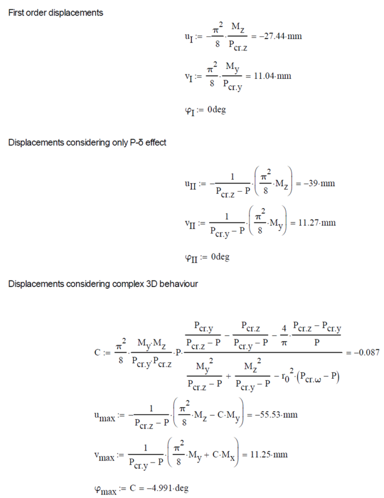
First order
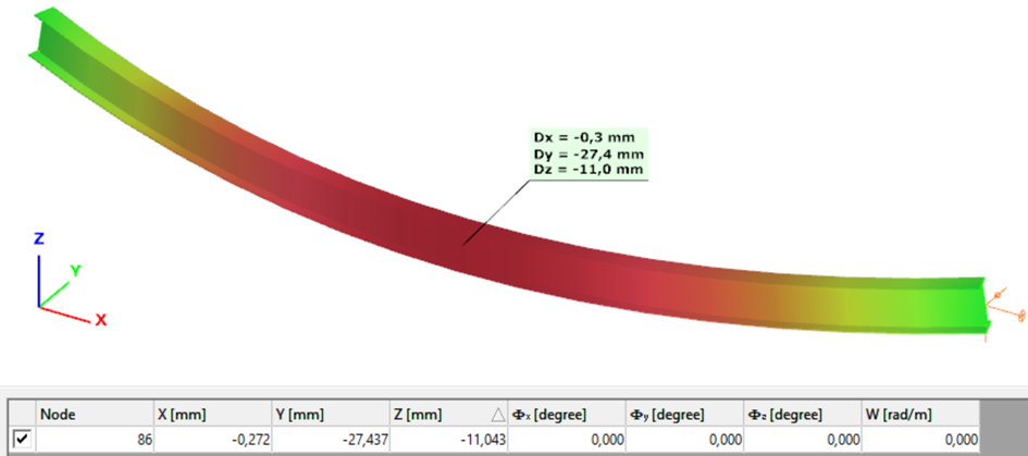
Second order – 6DOF beam element
The second order deformation of the member which was computed by the ConSteel software. It is visible that there is no torsion, only increments of the lateral displacements due to P-δ effect:
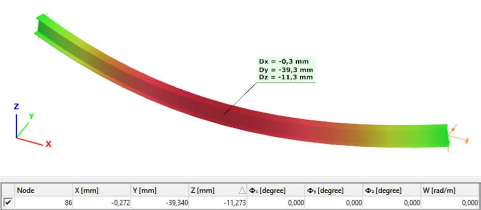
Second order – 7DOF beam element
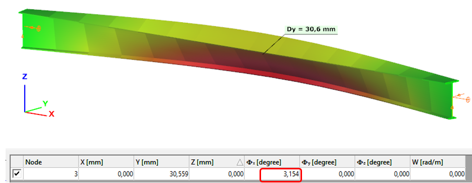
The second order deformation of the member which was computed by the ConSteel software using the 7DOF beam finite element model (n=16). It is visible that there is torsion and further increment in the lateral displacement (Dy):
Second order – Shell finite element
The second order deformation of the member which was computed by the ConSteel software using the shell finite element model (δ=25mm):
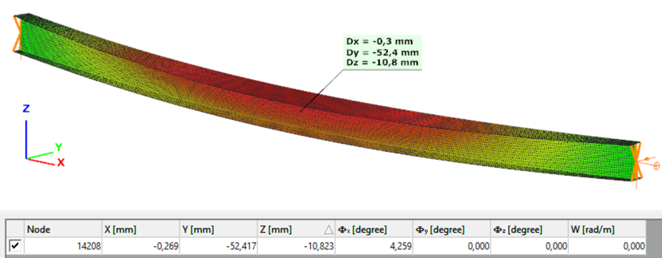
Second order – Superbeam
The second order deformation of the member which was computed by the ConSteel software using the Superbeam model (δ=25mm):
Introduction
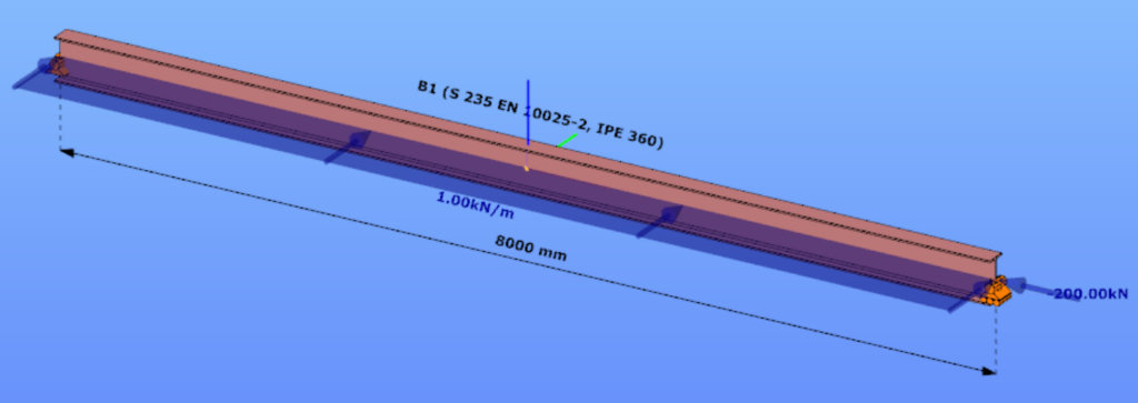
This verification example studies a simple fork supported beam member with IPE 360 section subjected to axial force and bending about the minor axis due to lateral, distributed force. The second order bending moment and the maximum axial compressive stress of the member is calculated by hand and by the Consteel software using the 7DOF beam finite elements.
Geometry
Calculation by hand

Computation by Consteel
Version nr: Consteel 15 build 1488
7DOF beam element The second order bending moment diagram of the member which was computed by the Consteel software using the 7DOF beam finite element model:
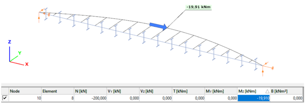
Normal stress in the middle cross-section:
Introduction
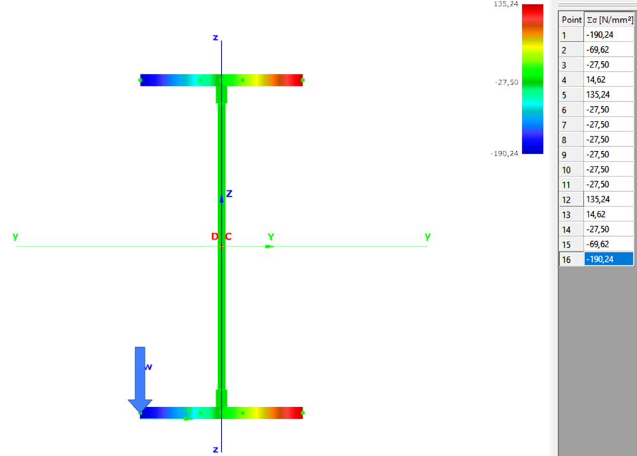
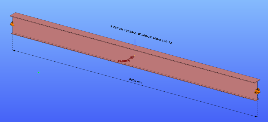
Our verification examples are created to be able to compare hand calculation results with Consteel anaysis results with using either 7DOF beam or shell finite elements. This example is a member of mono-symmetric I- section loaded with transverse concentrated load.
Geometry
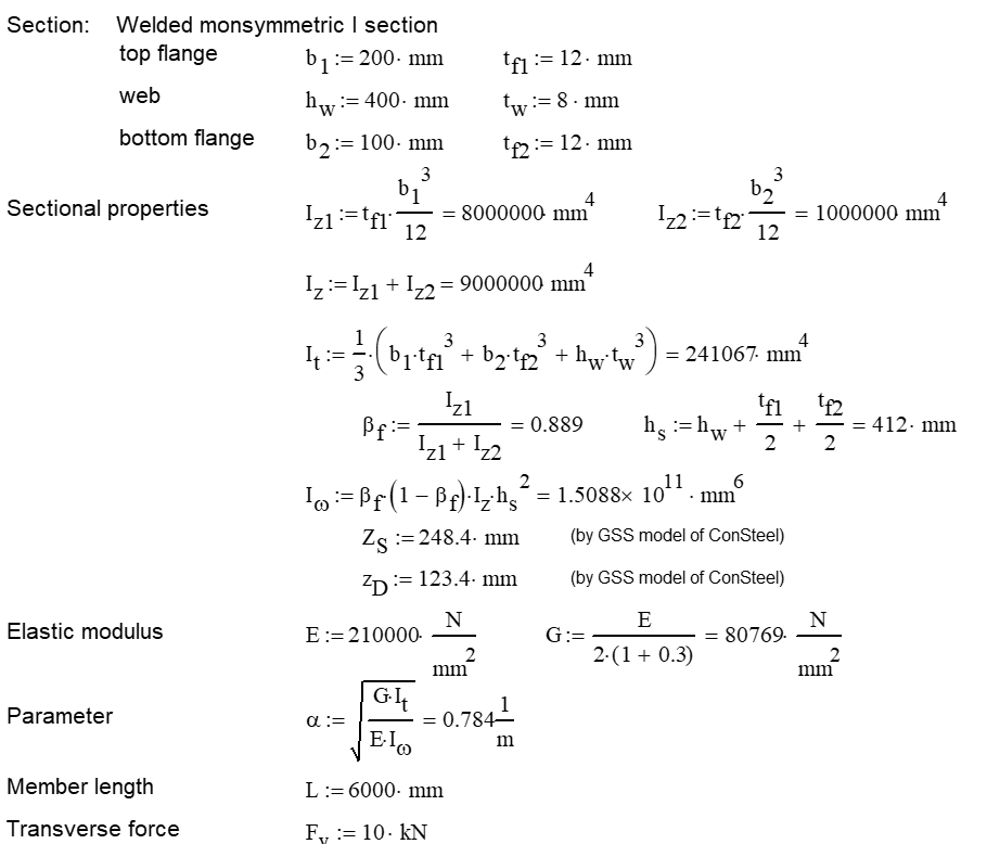
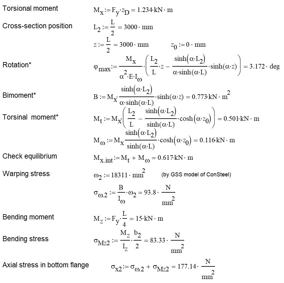
Calculation by hand
Computation by Consteel
Version nr: Consteel 15 build 1488
- 7DOF beam element
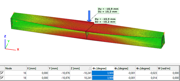
Deformation of the member with the numerical value of the maximum rotation (self-weight is neglected):
Introduction
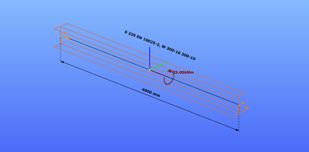
Our verification examples are created to be able to compare hand calculation results with Consteel anaysis results with using either 7DOF beam or shell finite elements including Superbeam function. This example is a member in torsion loaded with concentrated torque.
Geometry
Calculation by hand


Computation by Consteel
Version nr: Consteel 15 build 1488
- 7DOF beam element
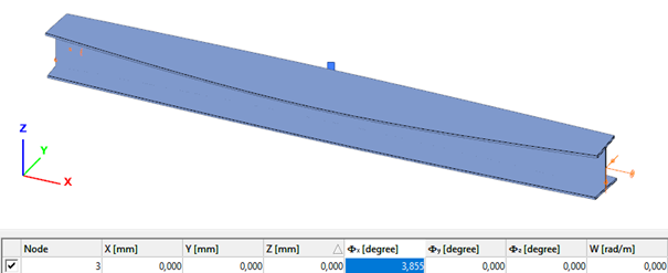
Deformation of the member due to concentrated twist moment:
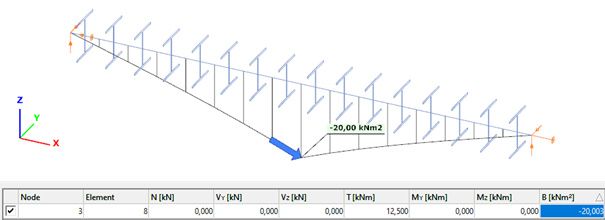
Bimoment of the member due to concentrated twist moment:
Warping normal stress in the middle cross-section:
- Shell FE model
Maximum deformation of the middle cross-section:
Civil engineering software in general use the traditional beam-type deformation representation where the section is shown on the deformation of the reference line. In Consteel 15 we use an advanced method for deformation representation which makes it smooth and realistic. The analysis results are the same, but with the improved visualisation the real 3D behavior of the structure can be better seen.
gate