Designing a lattice girder
The design of the bars of a truss (lattice girder) structure does not require any special theoretical knowledge: normally, the truss bars are designed as compressed and/or tensioned bars, neglecting bending moments and shear forces. The dimensioning of compression bars is nowadays carried out using a model-based computer procedure. For details, see the knowledge base material Design of columns against buckling. Here, only the determination of the deflection length of the compressed bars is presented.
The most important parameter for the dimensioning of a compressed bar is the slenderness:
$$\overline{\lambda}=\sqrt\frac{Af_y}{N_{cr}}$$
where
$$N_{cr}=\frac{\pi^2El}{(kL)^2}$$
where the buckling length factor k is recommended by EN1993-1-1 to facilitate manual calculations:
| Type of the bar | Direction of buckling | k |
|---|---|---|
| chord | – in-plane – out-of-plane | 0.9 0.9 |
| bracing | – in-plane – out-of-plane | 0.9 1.0 |
Software using model-based computational methods (e.g. Consteel software) determines the elastic critical force Ncr directly by finite element numerical methods, taking into account the behaviour of the entire lattice girder, instead of the above conservative formula. The following example is intended to illustrate the relationship between the manual design procedure proposed by the standard and the results of the modern model-based numerical procedure.
- Let the structural model of the lattice girder under consideration be the Consteel model shown in Figure 1.
- Let the load shown correspond to the design load combination of the girder.
- Determine the deflection length of the most stressed compressed chord member using finite element numerical stability analysis.
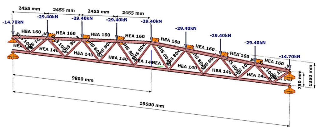
(Consteel software)
Relationship between procedures
The steps of the calculation are:
Buckling stability analysis
The stability analysis of the elastic model shows the governing buckling mode of the lattice structure and the corresponding elastic critical load factor αcr (Figure 2).
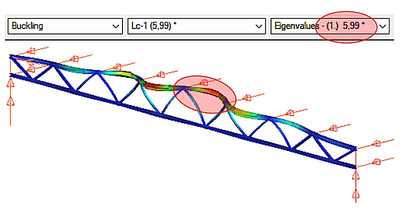
We can see that the upper chord of the perfectly elastic model is deflected laterally under load. The load that causes this elastic buckling is the critical load, whose value is given by the product of the design load and the critical load factor αcr=5.99.
gateThe evolution of compressed bar (column) design
One of the characteristic features of steel structures made of bars (e.g. lattice girders) is the compressed bar. We speak of a compressed bar when the structural element, which usually has a straight axis, is loaded by a compressive force P applied centrally (Figure 1).
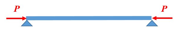
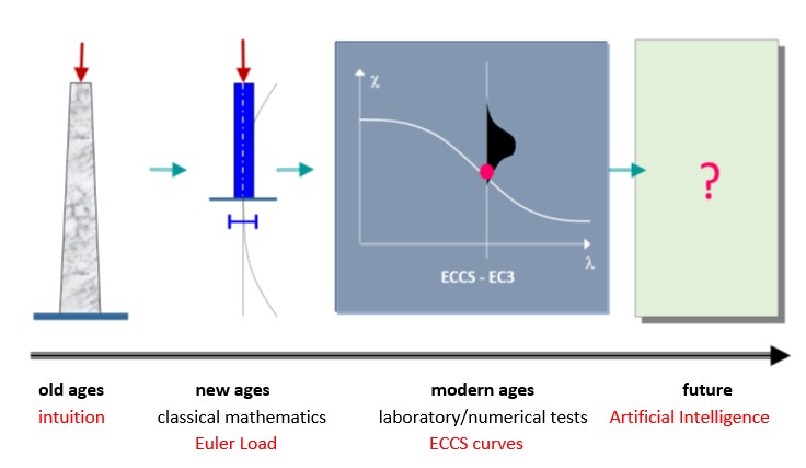
Figure 2 illustrates the evolution of compressed bar (column) design. In the beginning (in the old days), master builders determined the load-bearing capacity of compressed columns of different materials and sizes on the basis of the experience accumulated over the centuries, passed down from master to apprentice. A significant change was brought about by the application of classical mathematical differential analysis to engineering. The Swiss mathematician and physicist Euler (1707-1783) solved the problem of the deflection of a compressed elastic line, which could be applied to the solution of the elastic compressed bar (Euler’s force). In the following centuries, engineers recognised that Euler’s force only gave an acceptable approximation to the real load capacity of a compressed bar in certain cases (mainly for large slender bars). Many solutions for the bearing capacity of a compressed bar were developed that were more advanced than the Euler formula, but it was not until the huge structural engineering boom following World War II that significant changes were made. Compression bar experiments were carried out in every major structural laboratory in the world, and a database of over two thousand experiments was compiled from the results. The load capacity of the pressure bar was given by a formula based on the database, using the method of mathematical statistics.
This methodology is still dominant today: ‘the dimensioning of the compressed bar has become a political issue for the steel construction profession…’. Understanding the principle of compressed bar design is therefore essential for the structural engineer.
The right side of the Figure 2 also contains a hint for the future. At the level of scientific research, it is already present that the load capacity of a real compressed column can be determined by mathematical-mechanical simulation. Indeed, in the near future, databases that go beyond anything we know today can be created using supercomputers. On the basis of such a gigantic database, artificial intelligence could, at least in principle, supersede existing engineering knowledge and methodology. But the reality is that structural engineering is not one of the pull sectors (such as the defense or automotive industries), so this new shift in design theory is certainly a long way off.
In the following, the Euler force and the experimentally based standard design formula, which are of major importance to structural steel engineering today, are discussed in detail.
Buckling strength of the ideal columns: the Euler force
Assume that the hinged compressed column shown in the Figure 3 has the following properties:
- perfectly straight,
- its material is perfectly linearly elastic,
- centrally compressed.
Under the above conditions, perform the compressed column experiment using Consteel software: run the Linear Buckling Analysis (LBA) calculation. The result is illustrated in Figure 3.
gateDid you know that you could use Consteel to perform local and distortional buckling checks for cold-formed members?
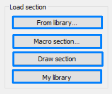
First, sections must be loaded into the model. To load cold-formed sections, you can choose from four options: From library, Macro section, Draw section, or My library.
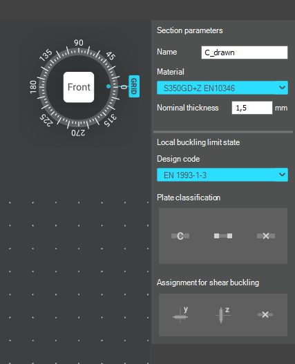
After the first-order and buckling analyses are completed, you can proceed to the Ultimate limit state check settings and enable the steel design cross-section and buckling checks. At the bottom of the steel design section, there is an option to Consider the supplementary rules from EN 1993-1-3 for the design of cold-formed sections. This checkbox must be selected if you want to design cold-formed sections.
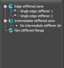
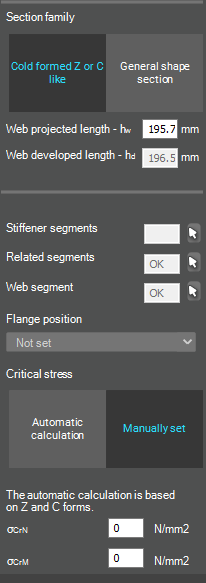
When the calculation is finished, by opening the Section module, we can review all the properties of the Effective section of the elastic plate segment model. By opening each plate element, we can verify the length, effective length, thickness, effective thickness, slenderness, and reduction factor separately. In addition, the properties of the stiffeners can also be verified: area, moment of inertia, lateral spring stiffness, critical stress, reduction factor, compressive stress, reduced effective area, and reduced thickness.
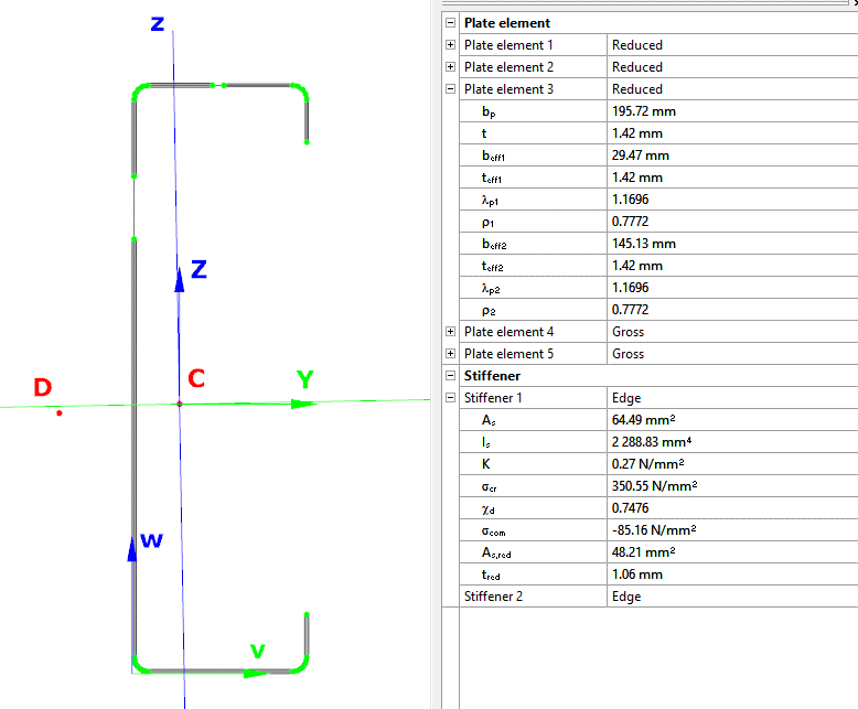
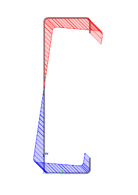
Similarly, the stresses can also be checked from the Properties tab. In the colored figure or diagram view, all the calculated stresses can be seen together with their resultants.
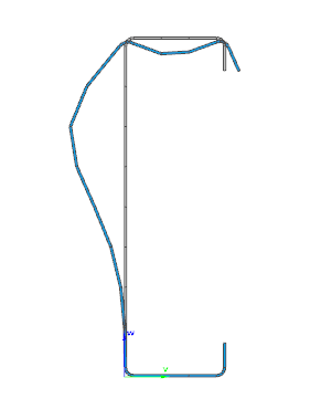
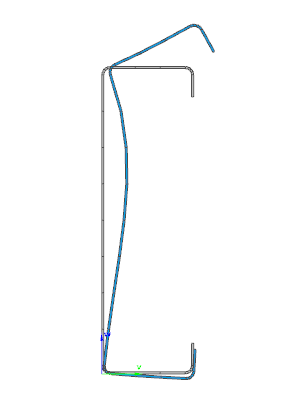
Consteel automatically takes into account the effect of distortional buckling when calculating the effective sections of cold-formed thin-walled sections.
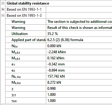
Moving on to the Standard resistance tab in the Section module, all calculated results can be verified, not only the dominant one. By opening the Global stability resistance check, we can see that, since we enabled the option to consider the supplementary rules from EN 1993-1-3 for the design of cold-formed sections, results are available both according to EN 1993-1-1 and according to EN 1993-1-3.
Download the example model and try it!
Download modelIf you haven’t tried Consteel yet, request a trial for free!
Try Consteel for freeThis paper discusses a combination of best practices and procedures from recent work in Europe and the US, providing rational and economical calculations addressing the complexities associated with frame design using nonprismatic members. Recommendations are provided in the context of US design practice. A primary objective is to achieve maximum simplicity, transparency, and design speed while facilitating rigor of the underlying calculations. The paper provides several focused examples illustrating the recommended design verification procedures.
Click the button below to download and read the full article.
GATEThe practical use of the ‘General method’ of EN 1993-1-1 6.3.4 for the buckling design of global structural models is still a challenging issue requiring several problems to solve. In this paper we propose a fully developed methodology presenting solutions for the application topics such as the suitable FE model, specific modeling issues to capture the true 3D behavior of the members and the whole model and the final evaluation of the design parameters. The presented methodology consistently uses a unique model for the evaluation of all analysis and design parameters and results and yields a fully automatic design process controlled solely by the properly created structural model.
Click the button bellow to download and read the full article.
gateWarehouse building example for Overall Imperfection Method in Consteel

Watch our user guide about How to use the Overall Imperfection Method to learn more.
gateOverall Imperfection Method in Consteel
The Overall Imperfection Method is an alternative way to carry out the buckling design for a structural member. With this method the buckling phenomenon is considered on the effect side of the equation, instead of on the resistance side, compared to the general method and the member check method. In the following video we explain the theoretical background for this calculation. After that we present application examples starting with the simplest ones, all the way to the most general case in a real-world building structure, showcasing the several extra capabilities and advantages of the Overall Imperfection Method.
Check out our user guide to learn more!
gateConsteel 14 is a powerful analysis and design software for structural engineers. Watch our video how to get started with Consteel.
Contents
- Set design parameters
- Perform cross section check
- Examine the design results in the Section Module
- Stability design according to the general method
- Member check – stability design for members
- Serviceability check
Part 2 – Imperfection factors
The Eurocode EN 1993-1-1 offers basically two methods for the buckling verification of members:
(1) based on buckling reduction factors (buckling curves) and
(2) based on equivalent geometrical imperfections.
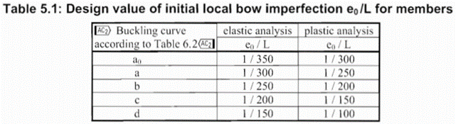
In the first part of this article, we reviewed the utilization difference and showed the relationship between the two methods. It was concluded that the method of chapters 6.3.1 (reduction factor) and 5.3.2 (11) (buckling mode based equivalent imperfection) are consistent at the load level equal to the buckling resistance of the member, so when the member utilization is 100%. The basic result of the procedure in 5.3.2 (11) is the amplitude (largest deflection value) of the equivalent geometrical imperfection. However, the Eurocode gives another simpler alternative for the calculation of this amplitude for compressed members in section 5.3.2(3) b) in Table 5.1, where the amplitude of an initial bow is defined as a portion of the member length for each buckling curves (Fig. 1.). We use the first column (“elastic analysis”) including smaller amplitude values.
It is an obvious expectation that these two standard procedures should yield at least similar results for the same problem. However, this is by far not the case in general.
In order to show the significance of the imperfection amplitudes this part is dealing with these two calculation methods, the variation of their values and the effect on the buckling utilization.
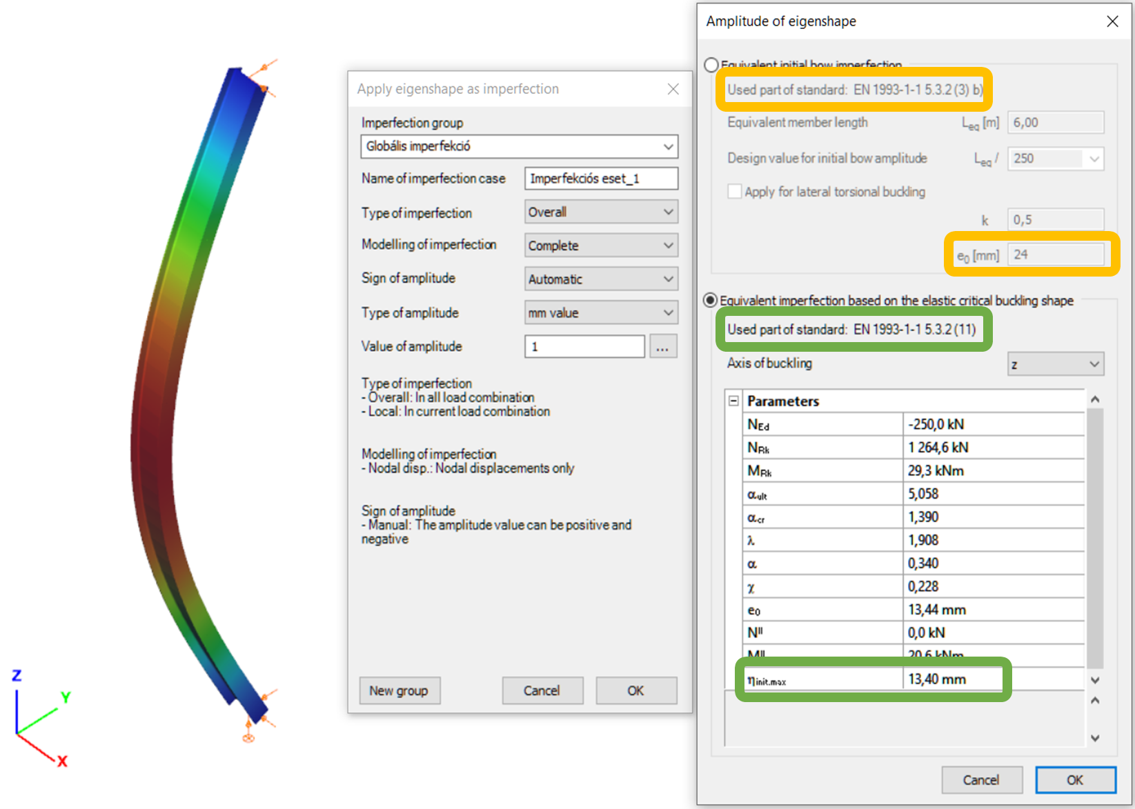
Let’s see again the simple example of Part 1: a simply supported, compressed column with a Class 2 cross-section (plastic resistance calculation allowed). The column is 6 meters high and has an IPE300 cross-section made of S235 steel. The two methods are implemented into Consteel and on Figure 2. it can be seen, that the two values for the amplitude of the geometrical imperfection is very different – e0 = 24 mm by the 5.3.2(3) b) Table 5.1 (L/250) and e0 = 13,4 mm by the 5.3.2 (11) (same as in Part 1).
Introduction
There are different ways to evaluate the stability of a structure. It is important to know the differences between those methods and the limits of applicability but it is also important to recognize the equalities in pure cases.
Methods of stability design
In Eurocode 1993-1-1, and so in Consteel, there are 3 methods to verify the stability of a model:
- Imperfection approach (described in Section 5.2 and 5.3)
The structural model is subjected to appropriate geometrical imperfections and after completing a second order analysis, only the cross section resistances need to be checked
- Isolated member approach ( described in section 6.3.1, 6.3.2 and 6.3.3)
The method is based on two essential simplifications:
- Structural member isolation: The relevant member is isolated from the global structural model by applying special boundary conditions (supports, restraints or loads) at the connection points which are taken into account in the calculation of the buckling resistance
- Buckling mode separation: The buckling of the member is calculated separately for the pure modes: flexural buckling for pure compression and lateral-torsional buckling for pure bending. The two effects are connected by applying special interaction factors.
- General method (described in section 6.3.4)
The basic idea behind the general method is that it no longer isolates members and separates the pure buckling modes, but considers the complex system of forces in the member and evaluates the appropriate compound buckling modes. The method offers the possibility to provide solutions where the isolated member approach is not entirely appropriate:
-The general method is applicable not only for single, isolated members, but also for sub frames or complete structural models where the governing buckling mode involves the complete frame.
-The general method can examine irregular structural members such as tapered members, haunched members, and built up members.
-The general method is applicable for any irregular load and support system where separation into the pure buckling modes is not possible.
Implementation of different approaches in Consteel
Isolated member approach is basically the reduction factor method and it can be performed in Member checks function in Consteel where it is possible to define the design parameters (e.g. effective length) by hand.
In Global checksfunction, cross-section and global buckling checks can be executed automatically according to the General method which does not require the direct introduction of effective lengths and other parameters depending on the distribution and combination of stresses along the member.
However, in pure cases (pure compression, or pure bending), buckling length calculated from general method can be equated with isolated member approach. In the following, a “how to” example will be shown on a pure compression column:
How can I get the buckling length of a certain member?
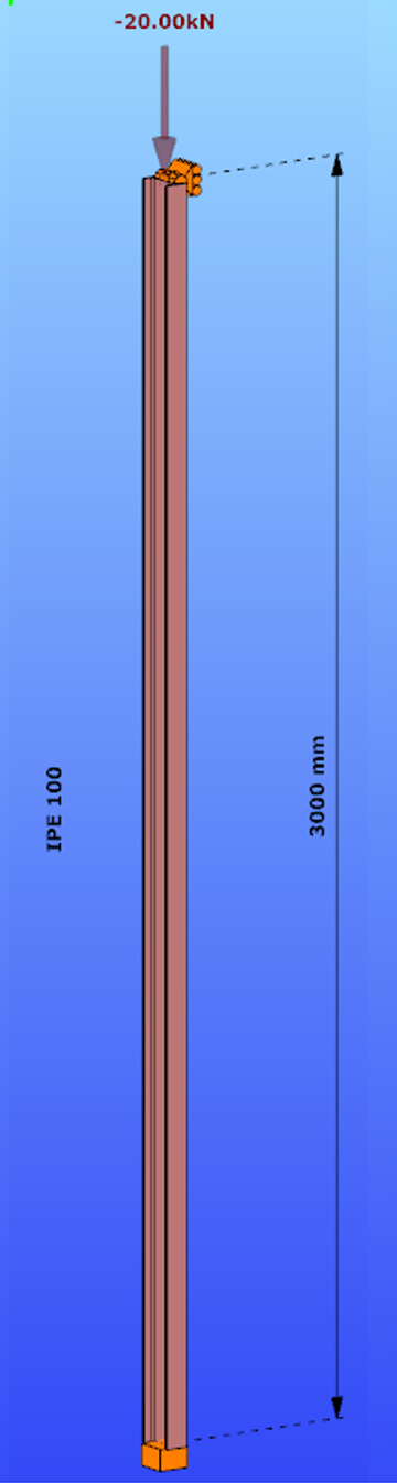
Parameters:
- Section: IPE100
- Material: S235
Main inertia around axes:
- Iy = 1708644 mm4
- Iz = 158056 mm4
Supports:
- x,y,zz on the top
- fixed on the bottom
Load: NED = 20 kN
Both the Isolated member approach and the General method require to calculate the slenderness value of the member. In case of the first method this is done through the use of buckling lengths. By using the General Method, the slenderness is calculated as the ratio of two amplifiying factors.
For the calculation of the equivalent buckling length we will need the first amplifier only, called critical elastic factor or alpha critical factor, obtained through a numerical analysis called linear buckling analysis.
Determination of alpha critical factor with buckling analysis:
Alpha critical factor: Minimum amplifier for the design loads to reach the elastic critical resistance of the structural component with regards to lateral buckling.
gate