In this article, we aim to answer the question: Why are there two different procedures for exporting connections to IDEA StatiCa? Let’s explore the difference between using the Connection interface and Checkbot export.
IDEA StatiCa Connection
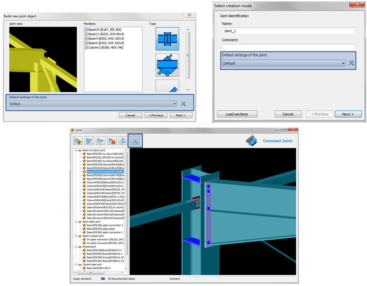
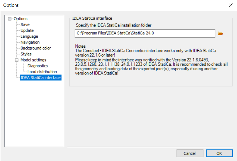
In order to use the IDEA StatiCa Connection link, please make sure that the program is installed and that the folder location is specified in the IDEA StatiCa Interface ‘Options menu‘.
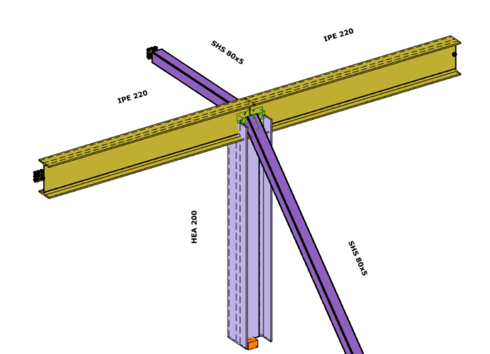
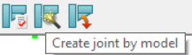
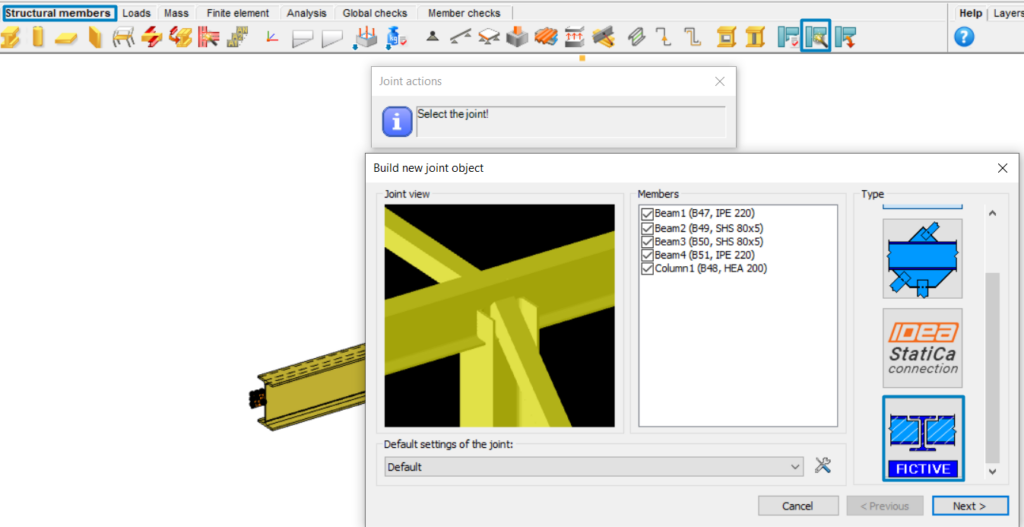
The conversion starts on the Structural Members tab, using the ‘Create Joint by Model‘ function. After selecting the appropriate intersection between members, a new window will appear.
If the ‘IDEA StatiCa Connection’ type is selected, the IDEA StatiCa application will launch automatically, and the selected connection will be transferred.
Using this method and placing the joints into the Consteel model (possible in multiple positions with similar geometry), a direct connection is established between the two programs. This means that geometry (cross sections, materials) and internal forces (according to all combinations of locations where the joint is placed) are taken directly from Consteel.
IDEA StatiCa Checkbot
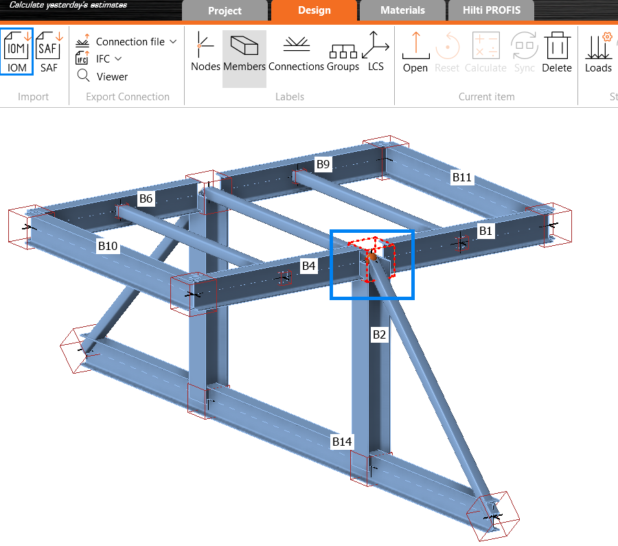
The IDEA StatiCa Checkbot export can be accessed from the ‘File menu’ by selecting it from the ‘Exports section’. Users must define a location where the entire model will be exported in .xml format. This file can later be imported into IDEA StatiCa Checkbot using the IOM (IDEA Open Model) import option.
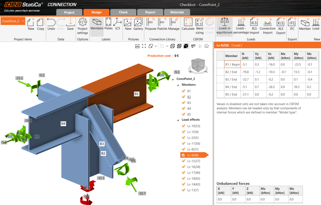
The full 3D model is imported using this method, and all joints can be analyzed individually within the IDEA StatiCa. A list of all imported items will appear in IDEA, each marked with a status such as ‘Checked’ or ‘Not Checked’. The imported members can be visualized in 3D, along with the applied loads.
The conversion supports materials, cross-sections, and load combination management. The internal forces resulting from the Consteel analysis for ULS combinations are available in IDEA StatiCa. This approach also ensures that the internal coordinate systems for all internal forces are preserved accurately.
All connections present in the imported model can be exported to IDEA StatiCa Connection, where joint design is carried out. You can choose to export a single connection or select multiple connections and save them in one file, allowing you to design the connection or print reports for all modeled connections at once.
Connections designed in Checkbot can only be considered in the global analysis phase in Consteel if the calculated stiffness is manually introduced at the release ends.
When to choose the direct link to IDEA StatiCa Connection?
Use direct link IDEA StatiCa Connection when you want to jump directly to the connection design in IDEA. Since the joint can be placed in multiple locations within the Consteel model, all internal forces from all combinations and all positions where the joint is placed will be taken into account.
A key advantage is that if you’re still working on your 3D model and changes occur, there’s no need to regenerate the link, simply update and verify the changes directly in IDEA StatiCa.
When to use IDEA StatiCa Checkbot Export?
Use Checkbot export when your structure contains many irregular or complex joints.For instance, if the bars in the connections do not intersect at a single point due to eccentricities or lack of space, you can merge them into one connection using Checkbot.

Conclusion
In summary, from the perspective of model updates and quicker access, using the direct connection via IDEA StatiCa Connection is generally the better choice, especially if the integrated Consteel Joint doesn’t provide enough flexibility for joint creation.
IDEA StatiCa Checkbot export offers significant advantages in terms of automated member recognition, possibility to merge joints, accurate assignment of internal forces, and efficient bulk joint analysis. It eliminates the need to manually verify force directions or coordinate systems, streamlining the workflow, especially for larger or more complex structures.
The main limitation of Checkbot export is that it establishes a one-way connection: every time the Consteel model changes, a new export is required in order to stay updated with the changes. Therefore, the choice between methods should depend on the nature of your project, if the model is expected to change frequently, the direct connection is more suitable. However, if you’re working with the final geometry and need to verify complex joints, the Checkbot export is the better option.
If you’ve ever wondered why there are so many joint types available when using the ‘Create Joint by Model’ function in Consteel, and when each type should be used, this article provides clear explanations directly from the developers.
Introduction
The process starts by selecting intersecting members using the ‘Create Joint by Model’ option under the Structural Members tab. It’s important that at least two members intersect so that a connection can be defined. Once selected, a window appears with a list of available joint types on the right. The list is dynamic and depends on the selected members. For instance, if the joint does not meet Eurocode standards, Consteel Joint connection types will not be displayed.
Consteel Joint
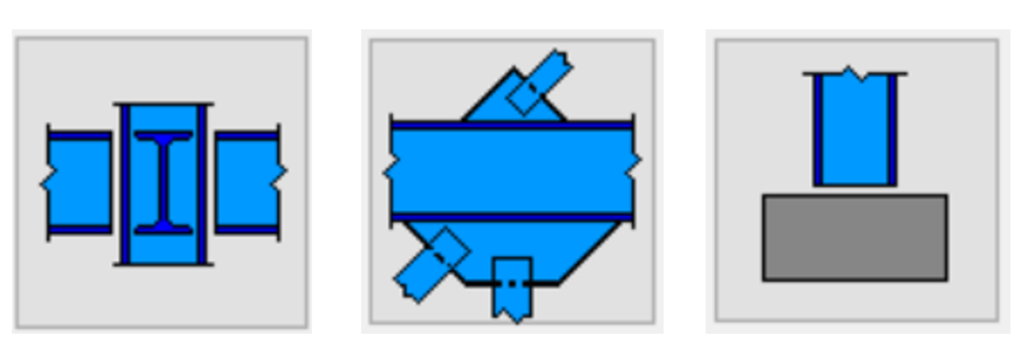
Consteel Joints are ideal for standard, Eurocode-compliant connection designs. When using the same ‘Create Joint by Model’ feature, depending on the selected elements, users may see multiple Consteel joint types. These can include connections like beam-to-beam joints with or without a main element, bracing connections that require the user to select the primary structural element, or column base joints, which can also be accessed via the spread footing tool.
Fictive Joint
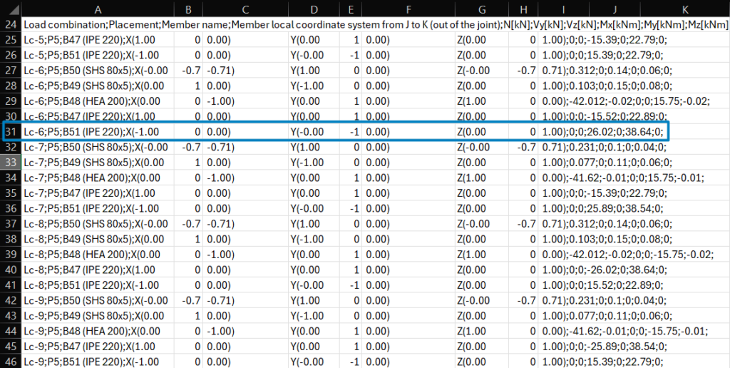
The Fictive Joint is particularly useful in collaborative design workflows where multiple teams or companies contribute to the structural design or when engineers decide to design the connections in their traditional way, using, for instance, handmade Excel spreadsheets. In such cases, specific joints may be designed externally, but all the necessary data is collected from the Consteel model and can be exported to a .csv file, Excel-compatibile format. This typically includes information such as placement, member names, local coordinate directions from J to K, internal forces and moments according to all analyzed load combinations.
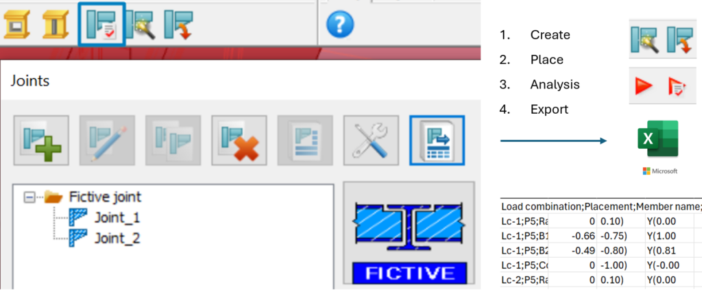
Using Fictive Joint, users can easily place the required joints in the model, categorize them according to type, and export all necessary data into a .csv file, Excel-compatibile format. It is important to note that data can only be collected after the Fictive Joints have been placed and the analysis has been run.
The Fictive Joint collects internal forces from each position where it is placed, streamlining communication with external design teams. If the structure is modified, it updates automatically after reanalysis, saving time and avoiding redundant work.
Make sure to export the .csv file after the final changes have been made.
Why choose Consteel Joint?
One of the biggest advantages of Consteel Joint is its full integration within the software. There’s no need to install additional plugins or manage separate licenses. The tool automatically uses all the modeled data—such as geometry and applied loads—making the process straightforward and efficient, accounting for all internal forces directly from the model, where it is placed. Another key benefit is that when joints are designed and placed directly in the model, their stiffness can be included in the overall 3D structural analysis. This results in more accurate and realistic calculations.
When to use Fictive Joints instead?
However, it’s important to note that Consteel Joints are only applicable for standard connection types. For special joints, where Consteel cannot perform the design, the Fictive Joint offers a flexible and practical solution for identifying, organizing, and sharing the necessary information with others.
Conclusion
In summary, Consteel Joints offers a powerful, integrated solution for standard connection design, while Fictive Joint is an essential tool for managing custom or externally designed connections. Understanding the purpose and capabilities of each will help you streamline your workflow and collaborate more effectively within complex design projects.
Did you know that you could use Consteel to calculate rotational stiffness for bolted column/beam moment bearing connections?
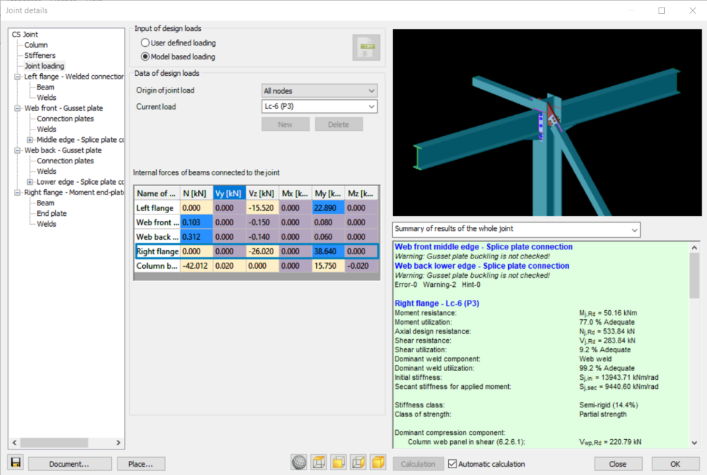
This capability is implemented through the Joint module, where connection behavior is evaluated in accordance with Eurocode EN 1993-1-8. The software does not treat joints as idealized (purely pinned or rigid), but allows the engineer to consider semi-rigid behavior by calculating the actual rotational stiffness based on connection components such as bolts, end plates, welds, and stiffeners.
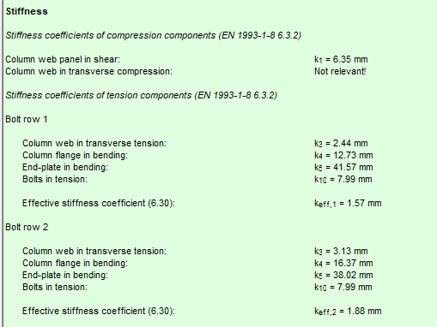
In practical terms, the rotational stiffness is derived from the component method, where the stiffness contribution of each tension and compression component is taken into account. This enables a more realistic representation of the joint response, especially for moment-resisting beam-to-column connections where stiffness significantly influences global structural behavior.
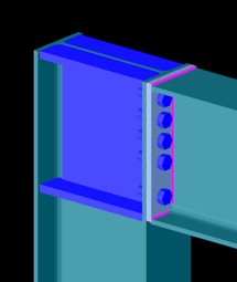
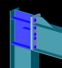
Bolted connection
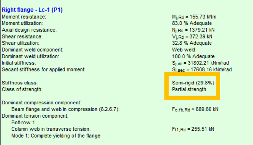
In this case, the connection exhibits relatively low rotational stiffness compared to a fully rigid joint. The flexibility is primarily governed by bolt deformation and end plate bending. Such connections are typically classified as semi-rigid and partial strength. They allow noticeable rotation under moment, which can be beneficial for redistribution of internal forces but must be considered in global analysis.
Bolted connection
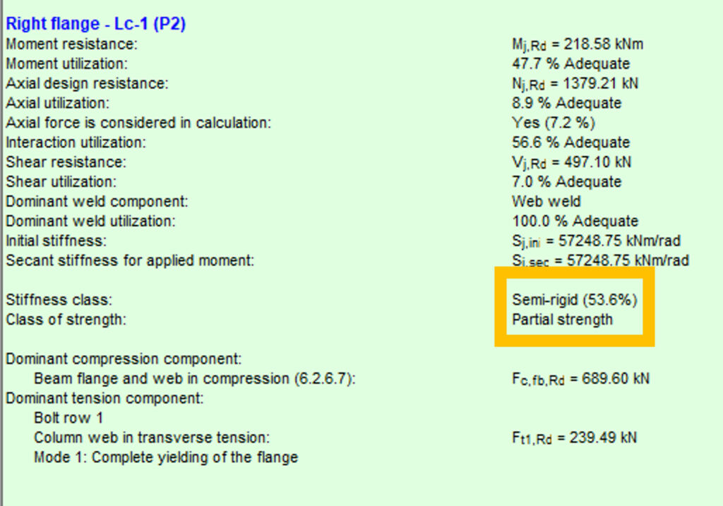
This configuration shows a higher stiffness due to improved component arrangement, such as thicker end plates, larger bolt diameters, or additional stiffening. Although still semi-rigid, the connection provides significantly more resistance to rotation. This intermediate behavior often results in a more efficient structural system by balancing stiffness and material usage.

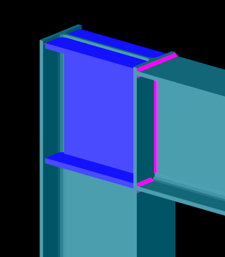
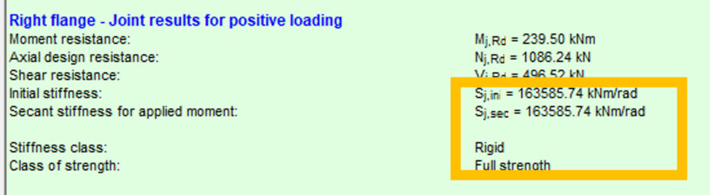
Welded connection
The welded joint behaves as a rigid connection with full strength. Rotational stiffness is high enough that joint deformation has negligible influence on the global structural response. In Consteel, this is reflected by a stiffness value approaching the rigid classification limit defined by the standard. Such connections are typically used where continuity and moment transfer must be ensured without significant rotation.
Using the Joint module, these behaviors can be modeled and evaluated through a structured workflow:
- Joint creation: Define the connection either manually or based on the global structural model using automatic recognition.
- Connection configuration: Assign geometry, cross-sections, bolt layouts, welds, and optional stiffeners.
- Loading definition: Apply either user-defined internal forces or import them directly from the global analysis.
- Analysis: The software evaluates moment resistance, shear resistance, and both initial and secant rotational stiffness using Eurocode-based procedures.
- Integration: The calculated stiffness can be applied back to the global model, enabling second-order effects and realistic force distribution.
Considering rotational stiffness leads to more accurate structural models. Instead of assuming ideal boundary conditions, the engineer can:
- Reduce conservatism in member design
- Capture redistribution effects in frames
- Optimize connection detailing
- Improve overall structural efficiency
This approach is particularly important in steel frames where joint flexibility can significantly affect deflections, internal forces, and stability.
Download the example model and try it!
Download modelIf you haven’t tried Consteel yet, request a trial for free!
Try Consteel for freeDid you know that you could use Consteel to consider connection stiffness for global analysis?
One of Consteel’s unique strengths is its ability to integrate joint modeling and calculation directly into the global analysis.
The Joint module performs all analyses in line with the standard procedures of Eurocode 3 Part 1-8, covering almost the entire scope of the code. This ensures results that are both reliable and fully compliant, across a wide range of connection types such as: Moment connections, Shear connections, Hollow section connections.
Modern structural design increasingly considers the mechanical interaction between the global model and its joints — whether rigid, semi-rigid, or pinned.
If you’d like to dive deeper into how semi-rigid joints influence structural behavior and stiffness classification, check out our detailed article: Semi-rigid joints in modeling of structures.
This integrated approach leads to results that are both more realistic and more economical, but it also requires more sophisticated modeling. Consteel makes this process straightforward:
- Joints can be created manually or automatically based on the model geometry.
- The create joint by model function examines member positions and cross-sections, then offers suitable joint types.
- Once defined, the joint can be placed into the global model, and its connection stiffness can be included in the global analysis.
- After placement, the joint is always rechecked against the latest analysis results.
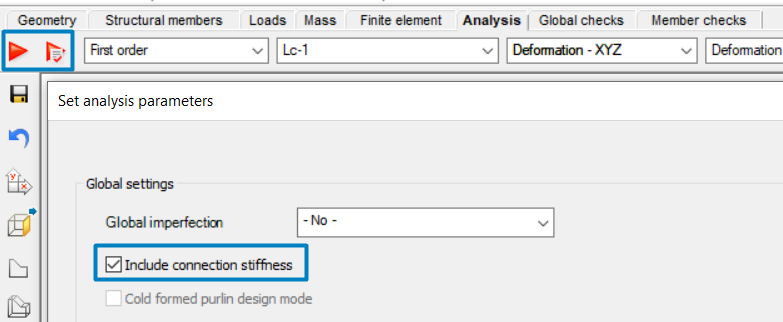
In order to consider the connection stiffness of the placed joint, open the analysis parameters, tick the Include connection stiffness checkbox, and rerun the analysis.
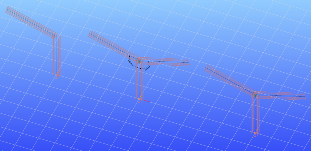
Let’s explore how the behavior of a simple frame changes under different connection assumptions:
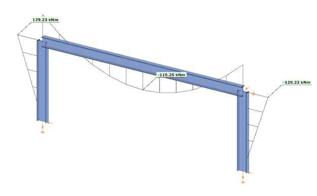
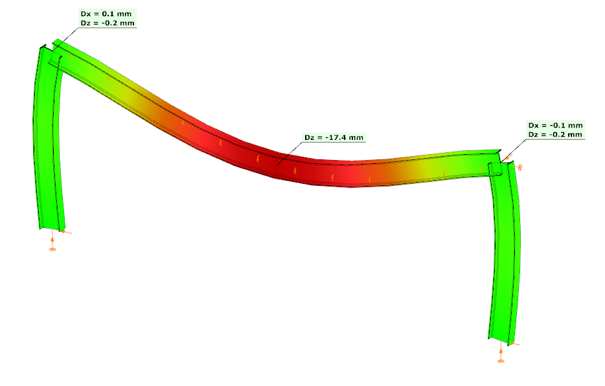
In the first case, where no actual connection stiffness was considered and the members were assumed to have continuous rigid ends, the results showed a bending moment (My) of 129.23 kNm at the column upper end and 115.25 kNm at the beam midspan. The corresponding deflection in the beam’s midspan (z-direction) was –17.4 mm.
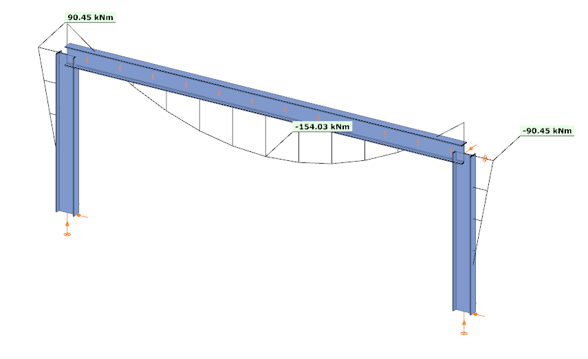
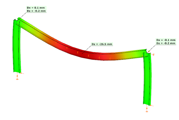
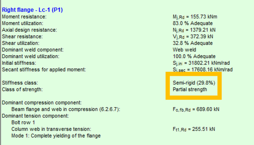
In the second case, the connections were modeled with their actual semi-rigid stiffness of 29.8% and partial strength. Here, the bending moment at the column upper end decreased to 90.45 kNm, while the beam midspan moment increased to 154.03 kNm. The beam midspan deflection reached –26.5 mm, representing an increase of 52% compared to the rigid assumption.

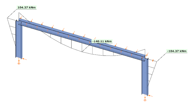
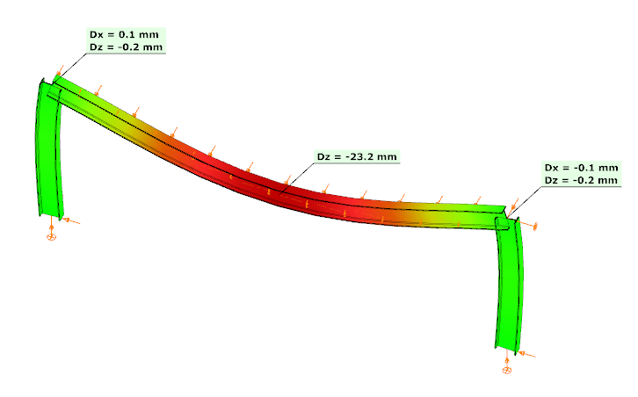
In the third case, with a higher semi-rigid stiffness of 53.6% and partial strength, the results balanced between the two extremes: the column end moment was 104.37 kNm, the beam midspan moment was 140.11 kNm, and the midspan deflection was –23.2 mm. This corresponds to an increase of 33% in deflection compared to the rigid assumption.

These examples clearly demonstrate how connection stiffness significantly influences global structural behavior. Assuming rigid connections may underestimate beam deflections and distort moment distribution, while considering realistic semi-rigid stiffness, provides a more accurate representation of structural performance.
Download the example model and try it!
Download modelIf you haven’t tried Consteel yet, request a trial for free!
Try Consteel for freeConsteel 14 is a powerful analysis and design software for structural engineers. Watch our video how to get started with Consteel.
Contents
- Build joint model based on the global model
- Bolted moment end-plate connection design
- Base plate connection design
- Apply connection stiffness in analysis
Read our tips and tricks about Choosing the orientation of a symmetric joint for more information.
Version: CS14.1000
Click the button below to download the model.
gateIntroduction
The effects of the behaviour of the joints on the distribution of internal forces and moments within a structure, and on the overall deformations of the structure, should generally be taken into account, but where these effects are sufficiently small they may be neglected.
Classification
In the case of elastic analysis, joints should be classified according to their rotational stiffness. The joints should have sufficient strength to transmit the forces and moments acting at the joints resulting from the analysis. A joint may be classified as rigid, pinned or semi-rigid, according to its rotational stiffness, by comparing its initial rotational stiffness Sj,ini with the classification boundaries given in EN1993-1-8 5.2.2.5. In the case of a semi-rigid joint, the rotational stiffness Sj corresponding to the bending moment MEd should generally be used in the analysis.
Calculation of joint stiffness
Consteel Joint calculates the Sj,ini initial stiffness of the joint, the Sj,sec secant stiffness for the actual loading and determines the classes of stiffness and strength (last one for plastic analysis).
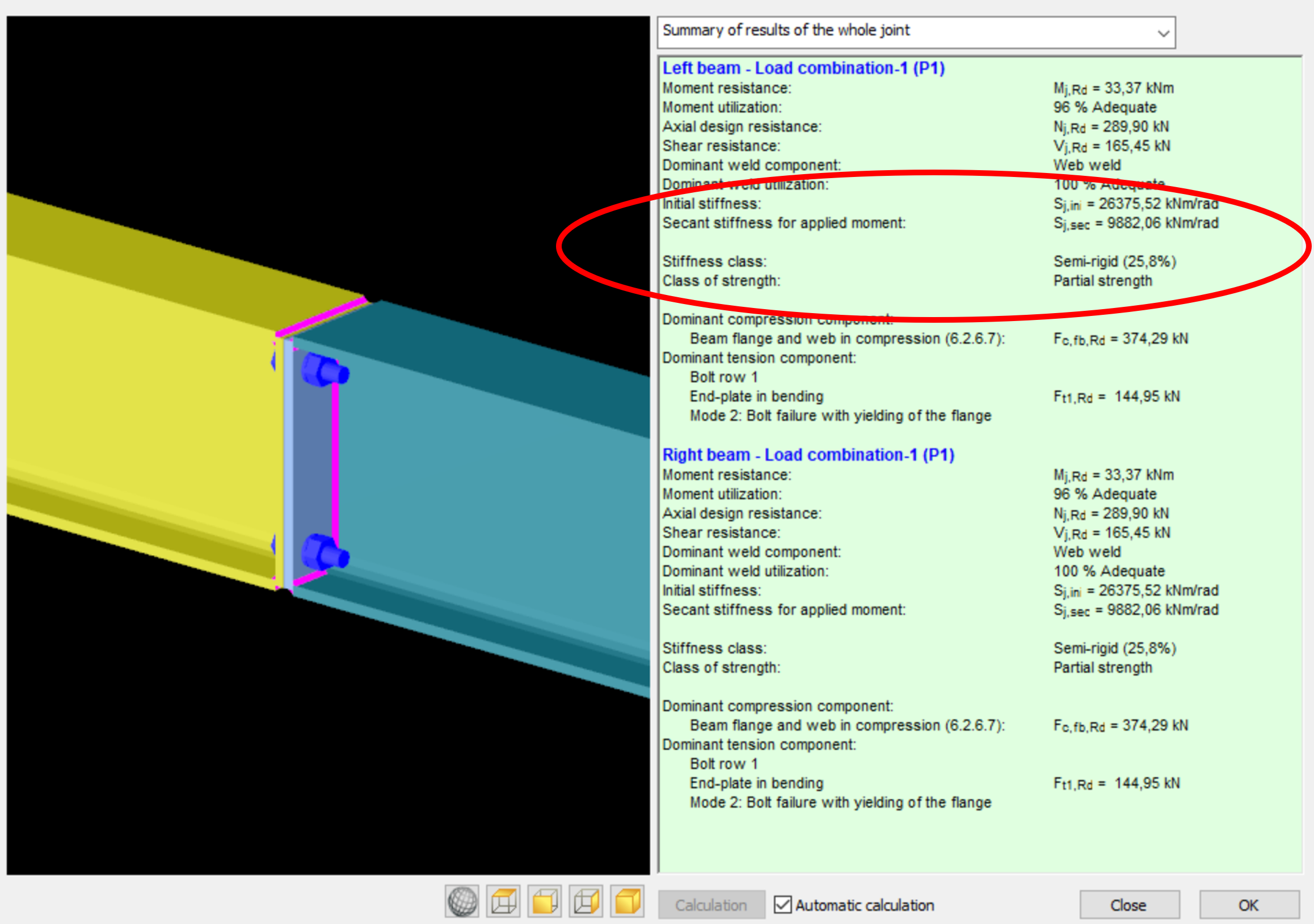
Sj,sec is equal to Sj,ini when MEd does not exceed 2/3*MjRd (EC3-1-8 5.1.2. (3) ), otherwise it is calculated.
Automatic consideration of connection stiffness
gateIntroduction
Joint orientaion can be chosen by the graphical display of the Place joint on the model function.
How it works
If there is only one option how to place a joint e.g. a single beam connected to a column, the orientation of the joint on the graphical display has no effect on the orientation of the placed joint.
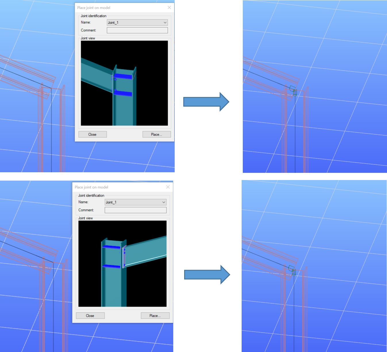
IF:
- There is more than one option on the placement and
- The geometry of the connected members are completely the same
the orientation of the joint on the graphical display will determine the orientaion of the placed joint.
Please see below an example for two different orientations of the same joint. In the first row of pictures the joint is placed in a way that the longer connection plate with the bolts outside the beam flanges is on the right side (‘Right flange’ on the picture). You can see in Consteel Joint that the higher (152 kNm) moment acts on the right side.
In the second row, the same joint is placed with opposite orientation – the long connection plate on the left side. It is visible that the 152 kNm is now on the other side (the one with the shorter plate and bolts inside the flanges).
gateIntroduction
When you create a new joint either manually or by model, certain parameters are set to a default value e.g. weld sizes, method of weld design, bolt material and diameters, stiffener plate properties etc…
When you’re working on a large model, or simply want to design more joints in Consteel Joint, setting these default parameters one by one (e.g. if you have a specified palette of bolts or plate material) at each joints would take a lot of time. In this case, creating a new, user defined default setting can be very helpful, and can save you time.
How it works
The default joint settings can be modified at the Default joint settings dialog. It can be opened either when creating a new joint (manually or by model) or from Joints dialog.