This overview delves into Consteel’s solution, offering an alternative approach to calculating effective cross-sectional properties and reshaping conventional methodologies in structural analysis and design.
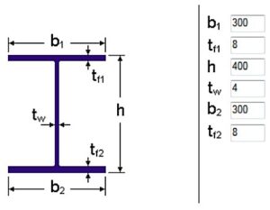
Determine the strength utilization of a double symmetric welded I cross-section with 384×4 web and 300×8 flanges, if the internal forces on the cross-section are NEd=500kN compressive force and My,Ed=100kNm bending moment. The material grade of the cross section is S235.
Calculation of cross-sectional properties
First, take the cross-section data (symmetric welded I-section), from which the Consteel software generates the EPS (and GSS) (see Online Manual/10.1.1 The EPS model) cross-section model (Fig. 1).
If the cross-section is class 4, the effective model is determined by the assumed normal stress distribution. According to EC3-1-1, the EPS model of a class 4 cross-section can be defined in two ways :
– method A: based on pure stress conditions,
– method B: based on complex stress condition.
In order to compare the results, the cross-section properties will be calculated by method A at first and then by method B.
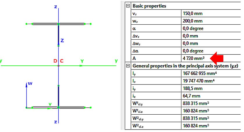
Cross-sectional properties by method A
- pure compression NEd (Fig. 2):
Aeff=4720mm2
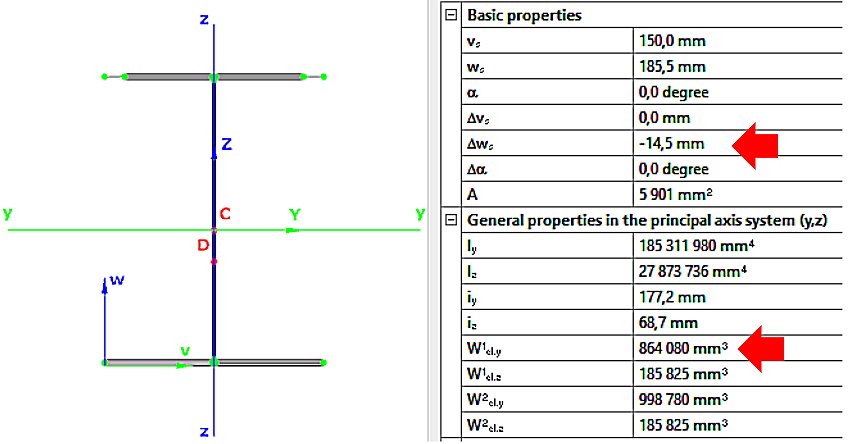
- pure bending My,Ed (Fig. 3):
Weff,y,min=864080mm3
ez=14.5mm
Cross-sectional properties by method B
GATEIn Consteel, the calculation of cross sectional interaction resistance for Class 3 and 4 sections is executed with the modified Formula 6.2 of EN 1993-1-1 with the consideration of warping and altering signs of component resistances. Let’s see how…
Application of EN 1993-1-1 formula 6.2
For calculation of the resistance of a cross section subjected to combination of internal forces and bending moments, EN 1993-1-1 allows the usage -as a conservative approximation- a linear summation of the utilization ratios for each stress resultant, specified in formula 6.2.
$$\frac{N_{Ed}}{N_{Rd}}+\frac{M_{y,Ed}}{M_{y,Rd}}+\frac{M_{z,Ed}}{M_{z,Rd}}\leq 1$$
As Consteel uses the 7DOF finite element and so it is capable of calulcating bimoment, an extended form of the formula is used for interaction resistance calculation to consider the additional effect.
$$\frac{N_{Ed}}{N_{Rd}}+\frac{M_{y,Ed}}{M_{y,Rd}}+\frac{M_{z,Ed}}{M_{z,Rd}}+\frac{B_{Ed}}{B_{Rd}}\leq 1$$
Formula 6.2 ignores the fact that not every component results the highest stress at the same critical point of the cross-section.
In order to moderate this conservatism of the formula, Consteel applies a modified method for class 3 and 4 sections. Instead of calculating the maximal ratio for every force component using the minimal section moduli (W), Consteel finds the most critical point of the cross-section first (based on the sum of different normal stress components) and calculates the component ratios using the W values determined for this critical point. Summation is done with considering the sign of the stresses caused by the components corresponding to the sign of the dominant stress in the critical point.
(For class 1 and 2 sections, the complex plastic stress distribution cannot be determined by the software. The Formula 6.2 is used with the extension of bimoments to calculate interaction resistance, but no modification with altering signs is applied)
Example
Let’s see an example for better explanation.
GATEDid you know that you could use Consteel to perform local and distortional buckling checks for cold-formed members?
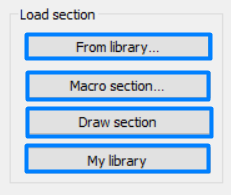
First, sections must be loaded into the model. To load cold-formed sections, you can choose from four options: From library, Macro section, Draw section, or My library.
After the first-order and buckling analyses are completed, you can proceed to the Ultimate limit state check settings and enable the steel design cross-section and buckling checks. At the bottom of the steel design section, there is an option to Consider the supplementary rules from EN 1993-1-3 for the design of cold-formed sections. This checkbox must be selected if you want to design cold-formed sections.
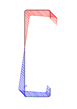
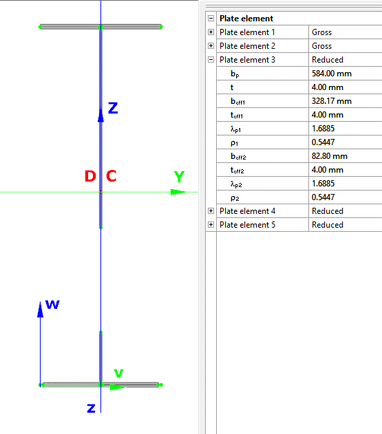
When the calculation is finished, by opening the Section module, we can review all the properties of the Effective section of the elastic plate segment model. By opening each plate element, we can verify the length, effective length, thickness, effective thickness, slenderness, and reduction factor separately. In addition, the properties of the stiffeners can also be verified: area, moment of inertia, lateral spring stiffness, critical stress, reduction factor, compressive stress, reduced effective area, and reduced thickness.
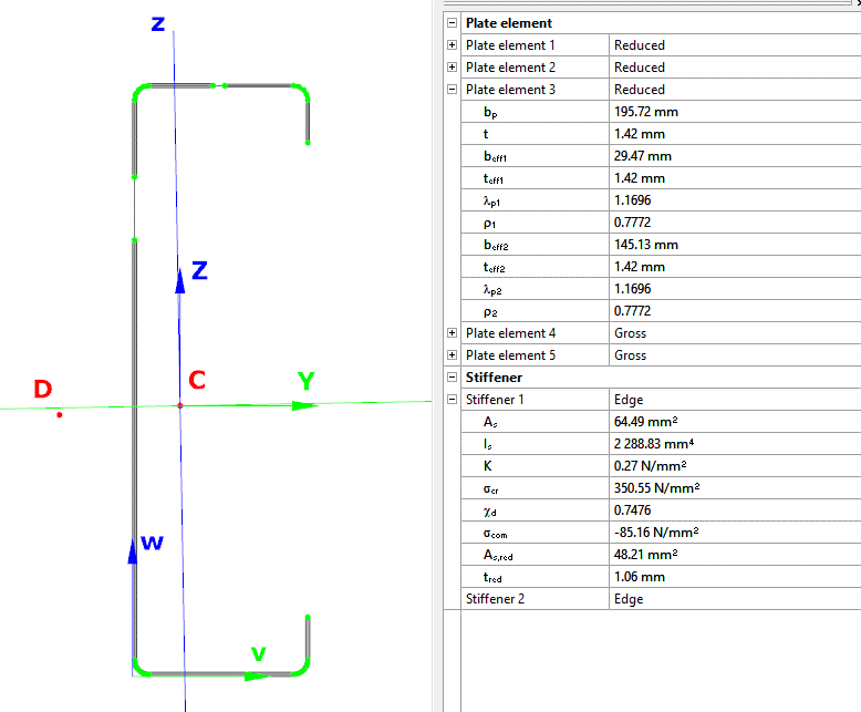
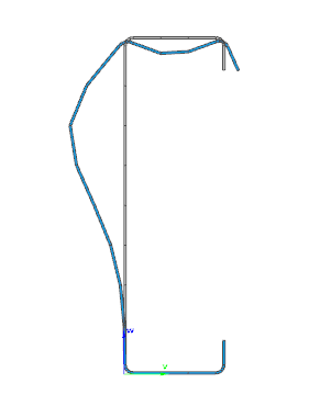
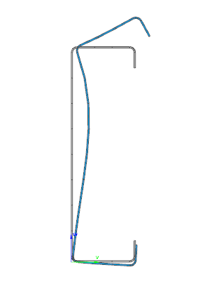
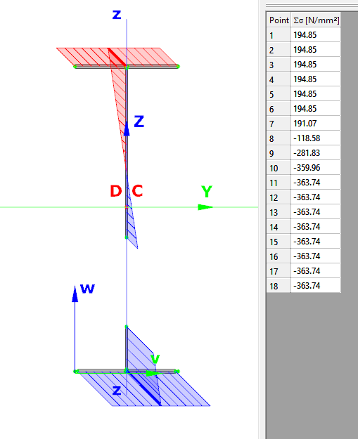
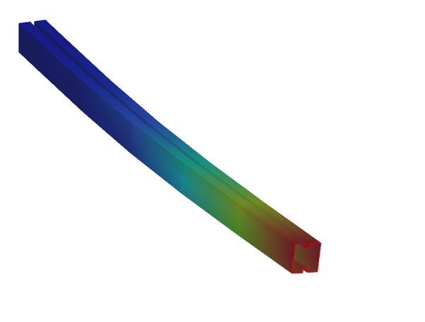
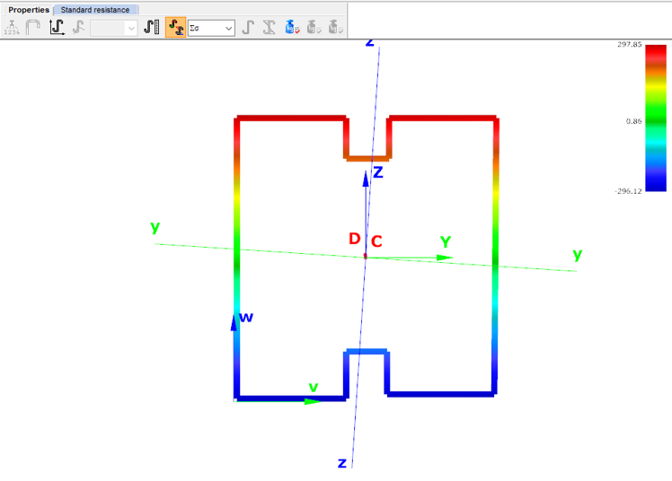
Similarly, the stresses can also be checked from the Properties tab. In the colored figure or diagram view, all the calculated stresses can be seen together with their resultants.
Consteel automatically takes into account the effect of distortional buckling when calculating the effective sections of cold-formed thin-walled sections.
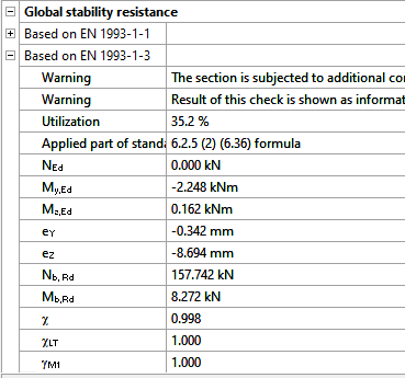
Moving on to the Standard resistance tab in the Section module, all calculated results can be verified, not only the dominant one. By opening the Global stability resistance check, we can see that, since we enabled the option to consider the supplementary rules from EN 1993-1-3 for the design of cold-formed sections, results are available both according to EN 1993-1-1 and according to EN 1993-1-3.
Download the example model and try it!
Download modelIf you haven’t tried Consteel yet, request a trial for free!
Try Consteel for freeDid you know that you could use Consteel to calculate effective cross-section properties for Class 4 sections?
The classification of cross-sections is used to understand how local buckling affects the strength and rotation capacity of structural members. As stated in Eurocode 3 (EN 1993-3-3, Section 5.5), this classification helps determine whether a cross-section can reach its full resistance or if its behavior is limited by local instability.
Class 4 cross-sections are those in which local buckling occurs before the material reaches the yield stress in one or more parts. Because of this, their resistance must be calculated using effective section properties that take into account the reduction caused by local buckling.
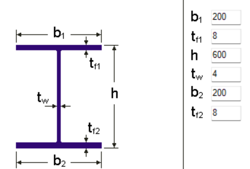
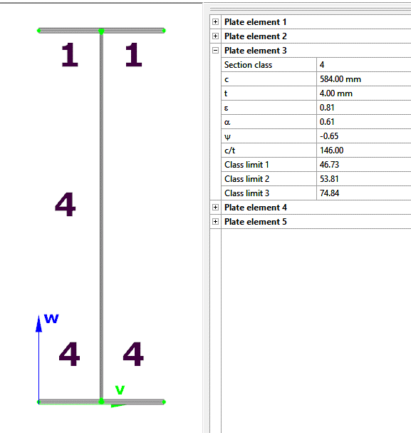
Typical Class 4 sections are characterized by slender elements with high width-to-thickness ratios. These commonly include thin webs or flanges, hollow sections (RHS/CHS) with slender walls, thin-walled cold-formed profiles such as C- or L-sections, and welded I-sections with slender webs. In this example, we consider a welded I-section with the following geometric parameters:
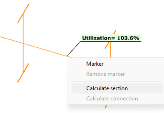
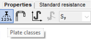
In Consteel, we can then see the section classification from the Global Checks tab. After selecting the investigated section either in the model or from the table and clicking on the Calculate Section option, and then choosing the Plate Classes in the Properties tab.
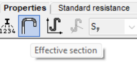
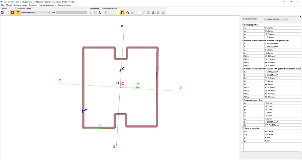
The effective section properties can then be viewed using the second option in the Properties tab.
In addition, stresses can be visualized by clicking on the Stresses icon. They can be represented either as a colored figure or as a 3D diagram.
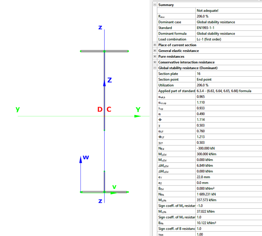
For Class 4 sections, the Standard Resistance tab in the section module provides a complete assessment for the selected loading case.
The section module performs all necessary calculations according to the Eurocode (EN 1993-1-1 and relevant parts of EN 1993-1-5), including general elastic resistance, pure case resistance, conservative interaction checks, and web buckling analysis.
All resistances are calculated using the effective section properties to account for local buckling, and the module identifies the dominant case to ensure all relevant checks are covered.
Download the example model and try it!
Download modelIf you haven’t tried Consteel yet, request a trial for free!
Try Consteel for freeDid you know that you could use Consteel to draw a user-defined cross section and calculate its section properties?
In our previous article, we showed how predefined macro geometries make modelling fast and efficient. Later, we demonstrated how Consteel evaluates local and distortional buckling according to EN 1993-1-3.
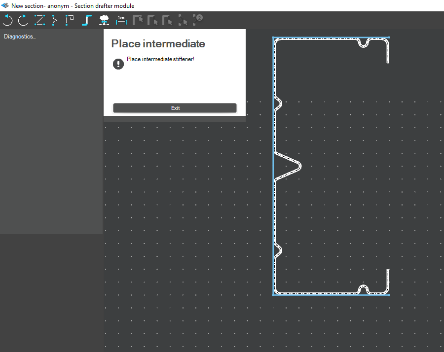
This article focuses on the most flexible solution within this workflow: creating your own cross-section from scratch using the Section drafter module.
For line member modelling, the cross-section must first be loaded into the model. Besides using standard library profiles or macro sections, you can also choose the Draw Section option. This function is especially useful when a special geometry is required that cannot be reproduced with predefined macros, for example manufacturer-specific shapes, research sections, welded thin-walled members, or prototype geometries.
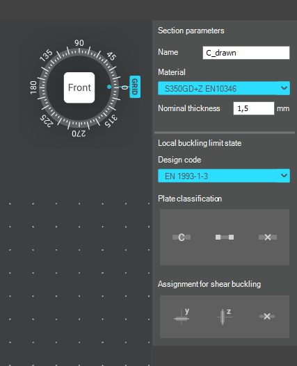
The Section drafter can be started from the Section Administration dialog by pressing the Draw section button. After launching the function, you need to select the section type, material quality and assign a name.
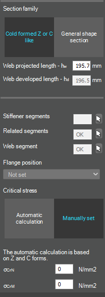
Two types of cross-sections are available: Cold formed section and General thin-walled section. This selection is not only geometric but also analytical.
Cold-formed sections are drawn with a single reference line and uniform thickness. During the calculation, Consteel automatically considers distortional buckling effects according to EN 1993-1-3. These sections can later be used in purlin line objects if they are defined as Z- or C-like shapes.
General thin-walled sections allow different thicknesses along the contour and closed geometries. They are typically used for welded or fabricated sheet sections. In this case, strength, local and global stability checks are available, but distortional buckling evaluation is not included.
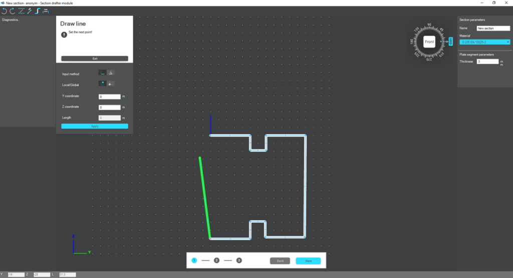
The drawing environment provides full control over geometry. Plate segments can be defined by coordinate input or by graphical selection. Cartesian or polar coordinates can be used, in local or global systems. Roundings are generated automatically between segments and can be modified later. The nominal thickness is also specified at this stage.
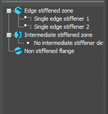
For cold-formed sections, stiffeners can be inserted using predefined macros, making it easier to model edge or intermediate stiffeners. However, these become structurally effective only after they are properly defined in the final phase of the section creation process.
Once the geometry is complete, the required design parameters must be specified. For cold-formed sections, this includes the manufacturing type, thickness tolerance category and buckling curves. These inputs influence the calculated design wall thickness and stability verification. In the next step, the program evaluates the classification of each plate segment and determines the effective widths used in resistance calculations.
If stiffeners are present, they must be defined explicitly. When the section is identified as Z- or C-like, Consteel can automatically determine the critical stress of the stiffeners in accordance with EN 1993-1-3. This ensures that distortional buckling and stiffener interaction are properly considered during design.
After saving the section, it can be assigned to line members just like any library or macro profile. Following structural analysis, steel design checks can be performed. As shown in our article on buckling checks, the Section module allows detailed review of effective cross-sectional properties, reduction factors, slenderness values and stiffener behaviour. Consteel automatically accounts for distortional buckling when the supplementary rules of EN 1993-1-3 are enabled.
By combining library, macro, and user-defined sections, Consteel provides a complete workflow: fast modelling with macros, precise verification through buckling checks, and full flexibility with custom cross-sections.
Download the example model and try it!
Download modelIf you haven’t tried Consteel yet, request a trial for free!
Try Consteel for freeDid you know that you could use Consteel to include in your model a wide range of cold-formed macro sections?
For line member modelling, the cross-section must first be loaded into the model. In Consteel, there are four options to do this, either starting from the Section Administrator or directly during beam or column modelling: From Library, Macro Section, Draw Section, or My Library.
Cold-formed sections can be created using any of these four methods. Standard cold-formed cross-sections can simply be selected from the library. However, if a special cold-formed section is needed, it can be created via Macro Sections, including: RHS, CHS, L profile, Z shape, C shape, Sigma section, Zeta section, Hat section with stiffeners, double C section, double Sigma section, and double user-defined sections.
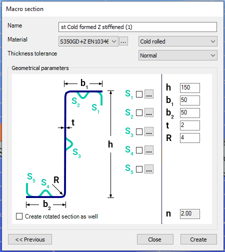
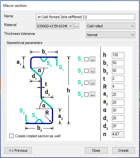
Macro sections are easy to create because the essential geometric characteristics are predefined, and the parameters can be modified intuitively. It is also possible to add profile stiffeners. Flange and web stiffeners can be configured in various forms, including single and double options. These defined stiffeners are included in the structural evaluation of distortional buckling, according to EN 1993-1-3.
The thickness tolerance category must be specified. This determines the design wall thickness for the section. In practice, macros follow the commonly applied tolerance categories used for coated steel sheet products.
If you want to use a double section, make sure to load into the model first the section that you want to duplicate.
For very special or unique sections, the Draw Section function can be used. This allows users to create fully custom cross-sections when standard or macro shapes are insufficient, by manually sketching the geometry.
Sections can be defined as cold-formed or general thin-walled, which determines how they are analyzed: cold-formed sections have uniform thickness and account for distortional buckling, while general thin-walled sections allow varied thicknesses and closed shapes, typically for welded or fabricated profiles.
This approach is especially useful for modelling unique shapes, prototypes, or as-built sections, giving full control over every segment to accurately capture geometries that standard libraries or macros cannot reproduce.
Download the example model and try it!
Download modelIf you haven’t tried Consteel yet, request a trial for free!
Try Consteel for freeIntroduction
It is essential for the effective work of the design engineers to have a model which is easy to overview. In Consteel there are several functions to achieve that such as layers and portions, and also Member coloring by cross-section.
How it works
The color of the displayed objects is now determined by the object style settings in Options.
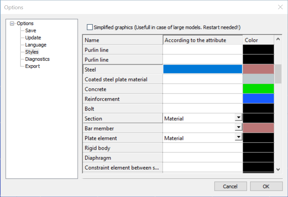
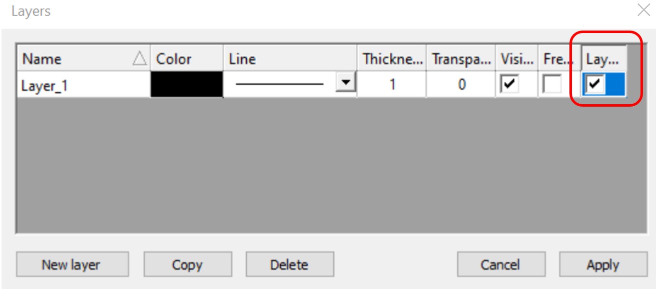
Layer color can overwrite these settings if the Layer style cell is checked on Layers dialog.
In the case of beam type members, it is also possible to set the color of the object according to the section it has defined. Coloring by member can be set with Object color setting dialog in the right bottom corner:
gate