Is a single dominant vibration mode sufficient, or should multiple vibration modes be considered in seismic analysis?
Steel portal frames are frequently used in industrial and logistics buildings as primary load-bearing structures. Their seismic behavior is strongly influenced by the stiffness of the roof diaphragm and by the interaction between the main portal frames and secondary structural subsystems such as endwalls.
In seismic design, engineers often assume that the global response of such buildings can be represented by a single dominant vibration mode. This assumption is valid when the roof diaphragm is sufficiently rigid and the first transverse mode mobilizes most of the structural mass. However, when the diaphragm is flexible or when different structural parts participate in different vibration modes, higher modes may also contribute to the seismic response.
This article investigates how the choice between a single-mode and a multi-modal approach affects the seismic design of steel halls modeled in Consteel. Through a comparative example, the study demonstrates the implications of different modal combination techniques and discusses how reliable internal forces can be obtained while maintaining compatibility with stability verification procedures according to EN 1993-1-1.
Case with a Rigid Roof Diaphragm
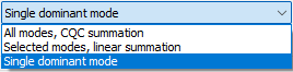
Single dominant mode
If a building is designed with a sufficiently rigid roof diaphragm, a single transverse vibration mode is typically able to mobilize close to 90% of the total participating mass. In such cases, the Single dominant mode method is an efficient and preferred design method.
A rigid roof diaphragm can be achieved by:
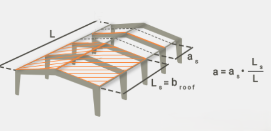
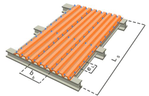
- Using an adequate trapezoidal steel deck, modeled in Consteel either
- as a Shear Field with a high shear stiffness parameter (“S” value), or
- by introducing equivalent dummy roof bracing diagonals with rod diameters calibrated to reproduce the diaphragm shear stiffness.
- Alternatively, real bracing elements may be added along the sidewall columns or from the eaves to the ridge along the building length.
Case without a Rigid Roof Diaphragm
If a rigid diaphragm is intentionally not assumed, a single vibration mode will generally not represent the full seismic response in the transverse direction.
Single dominant mode
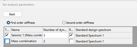
A dynamic eigenvalue analysis is first performed to determine the natural vibration modes of the structure. In Consteel, this analysis calculates the eigenfrequencies and corresponding mode shapes based on the structural stiffness and mass distribution, considering both the elastic stiffness and second-order geometric stiffness of the structure. The first three vibration modes are then evaluated for their mass participation in the transverse direction.
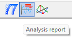
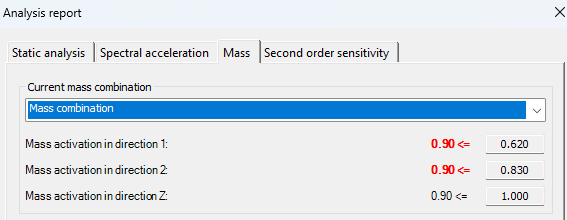
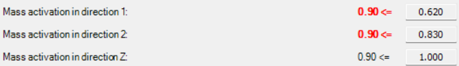
After the calculation, the mass participation for each principal direction (X, Y, and Z) can be viewed in the Analysis tab under the Analysis report, in the Mass section. In the examined case:
gateIntroduction
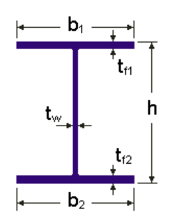
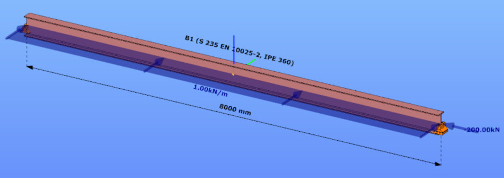
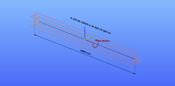
This verification example studies a simple fork supported beam member with IPE 360 section subjected to axial force and bending about the minor axis due to lateral, distributed force. The second order bending moment and the maximum axial compressive stress of the member is calculated by hand and by the Consteel software using the 7DOF beam finite elements.
Geometry
Calculation by hand

Computation by Consteel
Version nr: Consteel 15 build 1488
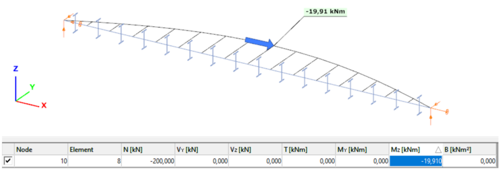
7DOF beam element The second order bending moment diagram of the member which was computed by the Consteel software using the 7DOF beam finite element model:
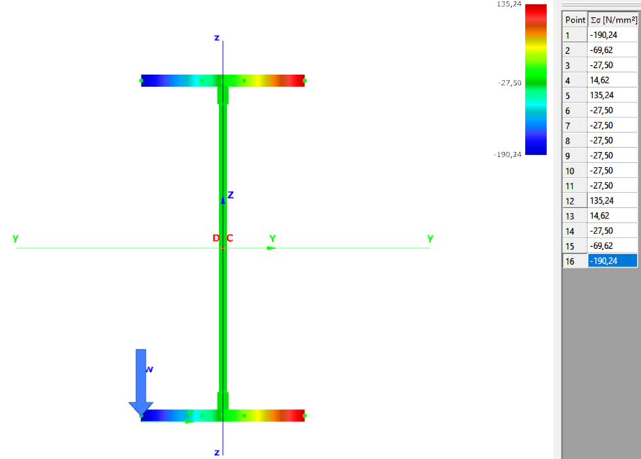
Normal stress in the middle cross-section:
Introduction
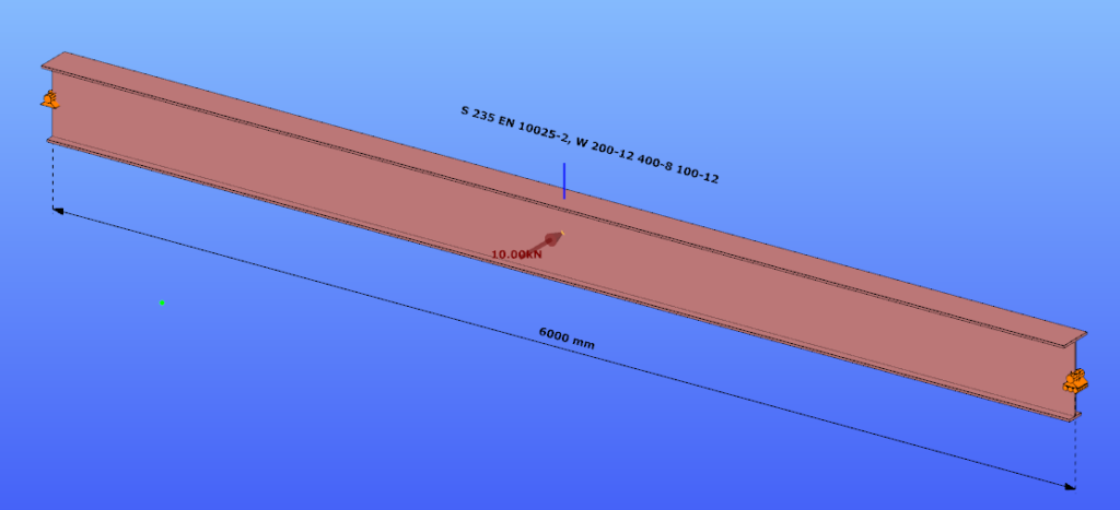
Our verification examples are created to be able to compare hand calculation results with Consteel anaysis results with using either 7DOF beam or shell finite elements. This example is a member of mono-symmetric I- section loaded with transverse concentrated load.
Geometry
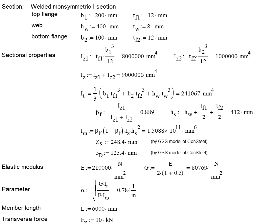
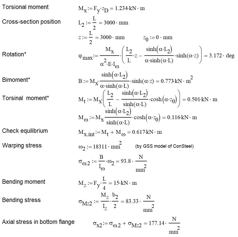
Calculation by hand
Computation by Consteel
Version nr: Consteel 15 build 1488
- 7DOF beam element
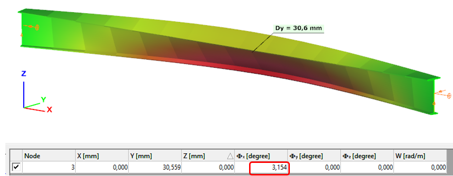
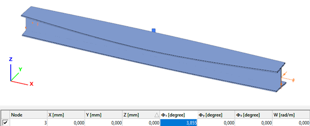
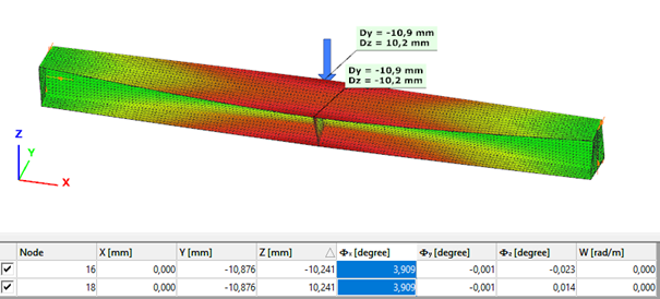
Deformation of the member with the numerical value of the maximum rotation (self-weight is neglected):
Introduction
Our verification examples are created to be able to compare hand calculation results with Consteel anaysis results with using either 7DOF beam or shell finite elements including Superbeam function. This example is a member in torsion loaded with concentrated torque.
Geometry
Calculation by hand


Computation by Consteel
Version nr: Consteel 15 build 1488
- 7DOF beam element
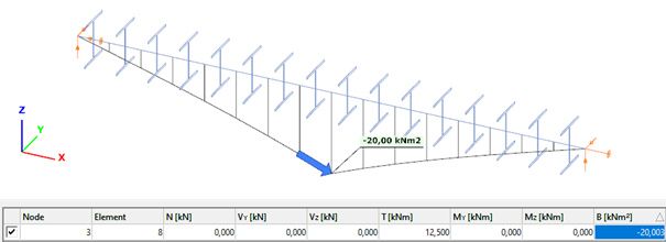
Deformation of the member due to concentrated twist moment:
Bimoment of the member due to concentrated twist moment:
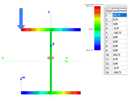
Warping normal stress in the middle cross-section:
- Shell FE model
Maximum deformation of the middle cross-section:
Introduction of Consteel Superbeam
In general, Consteel uses 7 DOF beam elements for finite element analysis of steel structures which are adequate for most everyday design situations. It is also capable of using shell elements in order to get more precise results in cases where beam finite elements are not sufficient enough. With the new Superbeam function it is now possible to examine structural parts with the accuracy of shell elements but with the ease of using a beam element concerning definition, modification, model handling, etc. In practice, it means that 7DOF beams can be switched to shell elements (and back) at any stage of the design process.
Validation
The validation program aims to verify the full mechanical behavior of the Superbeam switched to and analyzed as shell elements within a structural model composed of 7DOF beam elements. The validation of the analysis of the shell finite elements was done before and it is clear that in the case of correctly set boundary conditions the results are the same as the beam model provided that the local web buckling effect is avoided because it can not be modeled with beam-theory. Therefore the accuracy of the mechanical behavior of the Superbeam basically depends on two major factors:
- 1. the automatic shell modeling and mesh of the Superbeam
- When transforming a beam model in the structural analysis to shell model, several automatic transformations are done with the model objects (loads, supports, connected elements etc.) in order to yield a consistent mechanical model.
- 2. the mechanical consistency of the connections of Superbeam at the boundary to 7DOF nodes
- To satisfy the mechanical consistency at the connecting nodes the Superbeam uses automatically set constraint elements at both ends. They ensure the compatibility of the complete displacement field (translations, rotations, and warping) with the adjacent 7DOF beam finite element node or with the 7DOF point support.
The validation studies prove that the beam analysis model is mechanically equivalent to the shell analysis model within the Superbeam by comparing the results of the two models. It is shown that
- in the case of models where the local plate-like specific behavior is not relevant (thick plates in the cross-secions) the results are the same
- in the case of models where the local plate-like specific behavior is relevant (thin plates in the cross-secions) the results can be different only because of this plate-like behavior (local buckling, cross-section distortion) while the isolated beam-like behavior is the same
Part 1
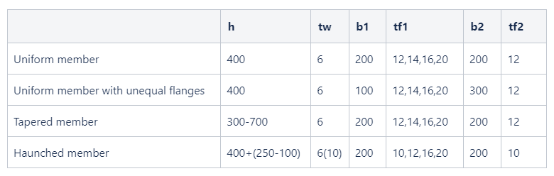
In this first part of the validation, we examined simply supported beams of welded I-sections with several different profile geometries. The full length of the beams was changed to Superbeam shell and so the consistency of results of both the shell elements and the constraints could be analyzed.
Structural models and analysis
In every case, the beam was first calculated with 7 DOF beam finite elements, after with Superbeam shell elements, and finally also as a full shell model with the same finite element sizes as the Superbeam shell. In full shell models, we applied rigid bodies along the edge of the web.
Linear buckling analysis was executed in order to compare the first buckling eigenvalues.
Our expectation was that the two kinds of shell models would produce very similar results which are by nature somewhat less favorable than the 7 DOF beam results, meaning that alfa critical values should be lower when using shell elements. To be able to compare the results related to global (lateral-torsional) buckling, the effect of local buckling of the web was to be avoided as much as possible so the examples were chosen accordingly.
Geometry