Are you looking to elevate your structural design process? Do you want to automate repetitive tasks and explore more creative solutions? Our new Introduction to Parametric Design training is designed to bridge the gap between traditional structural engineering and cutting-edge parametric design methodologies.
This training is tailored for both
- Consteel users who have heard about parametric design and Grasshopper but haven’t had the opportunity to dive in, and
- Grasshopper users looking to apply their skills specifically to structural engineering with Consteel.
Expand your design possibilities
Our training uniquely combines the strengths of multiple platforms:
- Rhino with Grasshopper: The industry-standard environment for parametric modeling
- Pangolin: Our custom plugin that bridges Grasshopper with structural engineering workflows
- Consteel’s Descript: Our powerful in-built scripting environment
By understanding how these tools work together, you’ll develop a comprehensive toolkit that spans from conceptual design through detailed structural analysis.
The training provides a balanced approach to both environments, ensuring you can leverage the full potential of parametric design in your work:
1. Foundation skills
- Navigate Rhino and Grasshopper’s interface specifically for parametric design
- Master Consteel’s Descript environment for streamlined scripting
2. Cross-platform workflows
- Connect Grasshopper and Consteel through live scripting
- Build a simple beam example to understand the fundamentals
3. Real-world applications
- Create a parametric transmission tower model—from wireframe geometry to full analysis
- Design and investigate a hall structure with a canopy
- Interpret Consteel results within Grasshopper for iterative refinement
4. Optimization techniques
- Compare optimization approaches in both Grasshopper and Descript
- Focus on section optimization for a simple truss design
- Learn practical methods for evaluating multiple design solutions
Why parametric design matters?
In today’s competitive environment, parametric design has become an essential approach for forward-thinking engineers and designers. The efficiency gained through automating repetitive tasks allows professionals to dedicate more time to creative problem-solving and innovative thinking.
Parametric methodologies enable teams to quickly evaluate multiple design alternatives, leading to more thorough exploration of possibilities that might otherwise remain undiscovered. Engineers can fine-tune their designs with unprecedented precision, optimizing for crucial factors like performance, cost-effectiveness, and sustainability benchmarks.
Perhaps most importantly, parametric design fosters improved collaboration by creating standardized workflows that enhance communication between architects and engineers, breaking down traditional silos that have historically limited interdisciplinary innovation. As structural engineering continues to evolve, these parametric approaches increasingly represent not just a competitive advantage but a fundamental shift in how we conceptualize and execute complex structural projects.
Ready to transform your design process?
This training represents an investment in skills that are becoming increasingly essential in modern structural engineering. Whether you’re looking to stay competitive in the industry or simply curious about expanding your capabilities, our Introduction to Parametric Design training provides the perfect foundation.
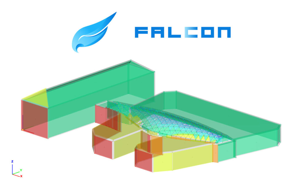
More about the trainingWe are excited to unveil the first version of our long-term development project: the FALCON plugin, a comprehensive wind load generator tool based on fluid-dynamics simulation. Let us know if you would like to participate in the testing.
We are about to release the first version of our wind load generator plugin
FALCON (Fluid-dynamics Aided Loads in Consteel) is a universal load-generation tool supported by fluid dynamics simulation, with the first integration to be released with the Consteel 18 release, in late Autumn 2024. It aims to provide structural engineers with the ability to determine realistic wind loads for any building type, comparable to standards.
Instead of creating a comprehensive simulation tool, that requires considerable expertise in fluid dynamics, we focus on the interpretation of the results. This approach builds on the logic of engineers’ wind load assessment and gives users more flexibility to apply their insights.
Free beta version
The FALCON plugin will be introduced in Consteel 18 in a free beta version, available for preliminary testing and use. Following a fine-tuning phase in collaboration with our dedicated users, the final version will be released next year.
Registration is required to use the beta version of FALCON.
We will involve you in testing
In pursuing our mission, to comprehensively reform the way structural design is done, we are committed to researching and implementing state-of-the-art methods of structural design, and always keeping an eye on the latest technological changes, while also placing great emphasis on fostering cooperation and the spirit of community.
That’s why we are launching an exciting new initiative that we want you to be part of.
We want to involve our users in testing and calibrating the beta version of the FALCON wind load generation plugin. This way, based on feedback and joint reflection, we can develop the final version, a tool that best suits your needs.
FALCON beta community testing/calibration
It’s worth taking part because:
- you have exclusive access to the beta version of the FALCON wind load generation plugin
- you can use FALCON for free during the testing period
- you can be the first to try out the new features
- you can be a member of a supportive professional community
- sharing your experiences and opinions is appreciated
- you will be part of the development of a new wind simulation tool
- you get discounts for active participation
The FALCON beta community testing process
- Registration for the FALCON beta community testing: from September 2024 – April 2025 onwards
- FALCON beta release: end of the Autumn 2024
- FALCON plugin demonstration webinar
- Online workshop sessions
- Roundtable discussion (last workshop session)
- FALCON training
- FALCON plugin release: Spring 2025
Discounts for cooperation
We also show our gratitude to test participants by offering them various discounts, depending on the intensity of their cooperation. You will be able to buy the FALCON wind load generator plugin with up to 50% discount and even participate in the related training courses for free.
Shape the future with us! By participating you can directly influence development. Share your opinions and suggestions with us, so we can shape the direction of Consteel’s development together!
Interested in this opportunity? If so, fill in our short application form. We will then contact you shortly with further details. There is no commitment at this stage. Don’t miss this opportunity, let’s make Consteel even better together!
JoinGot a question? Feel free to contact us at info@consteelsoftware.com. For further information about participating, see our Conditions of participation information.
Since we entered in the world of parametric design with our Grasshopper plugin Pangolin, we have observed numerous remarkable projects characterized by significant geometrical and structural intricacy. However, these projects are so unique that it is hard to effectively transfer the experiences and standardize certain parts of the parametric design workflow, particularly within design firms employing numerous structural engineers. But what happens in the case of modular or pre-engineered buildings? One of our customers has the answer. Let us delve into the details and then watch the accompanying video for a practical demonstration.
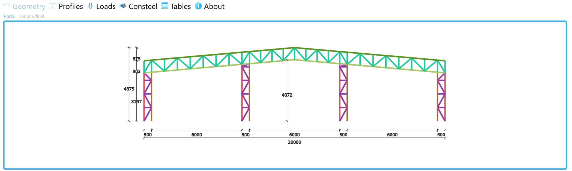
When one begins to implement parametric methodologies in design, it is essential to start with the end in mind, formulating a well-defined goal to minimize the number of parameters required. Mexi Steel, a designer and manufacturer of cold-formed steel buildings, had such a clear objective: a tool that could, based on their expertise, internal capabilities, and solutions, swiftly generate a mechanically accurate Consteel model according to a set of variables, with all potential loads evaluated in various cases and combinations. This tool should assist structural engineers in decision-making by providing precise material lists (beams and bolts) derived from the Consteel model results during the concept design phase, thus facilitating more accurate quotations. In collaboration with our local distributor, REFLEX Software, the first version of this tool was developed within approximately two months in 2022. The tool delineates the primary steps of the design workflow and offers a sequential user interface with multiple tabs.
First, the geometry at the portal level must be defined in 2D by specifying a few global or general dimensions of the building and providing information regarding the columns and rafters. Once the portal frame is generated and the loads are quickly evaluated, it becomes possible to examine the standalone portal and predesign the cross sections.
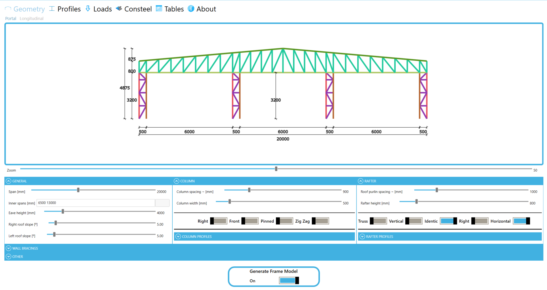
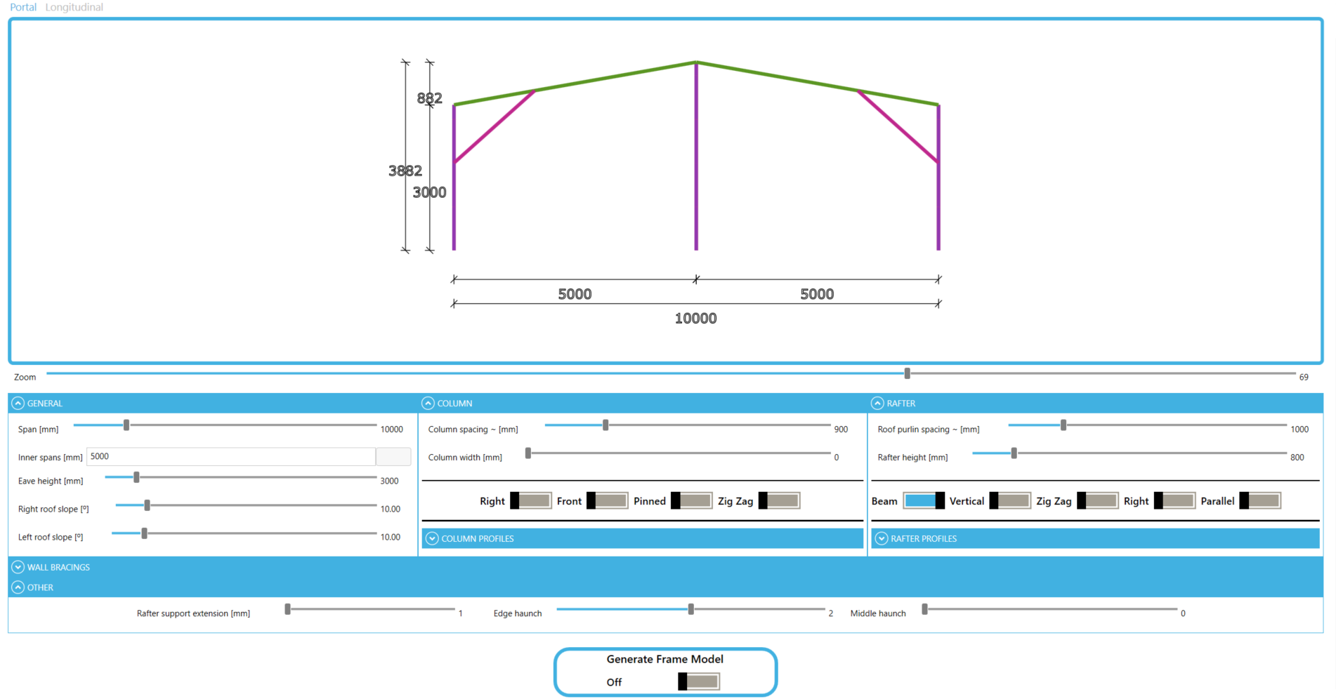
The next step involves defining the parameters in the perpendicular or longitudinal direction. When the portal frame is a truss, it consists of several members, and all translations of the main axis as well as rotations of the cross sections are considered using link elements in Consteel.
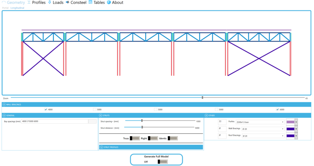
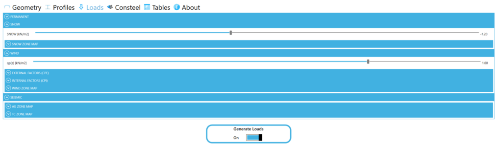
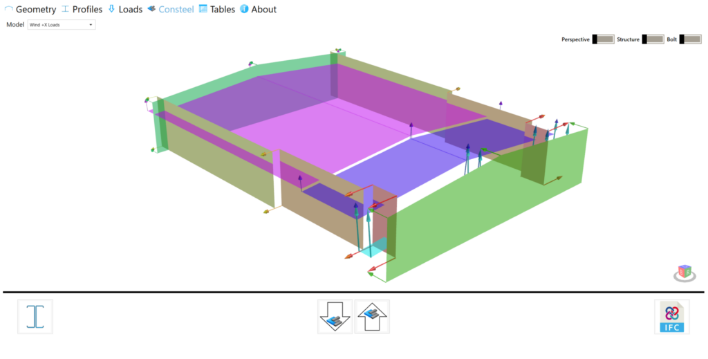
As a potential step, there is a posibility to expand the cross-section library, with typical cold-formed sections which can be manufactured by our customer. Then, as an essential step, all the load parameters have to be defined to obtain the desired ready-to-run Consteel model with all the mechanical objects, supports, loads etc.
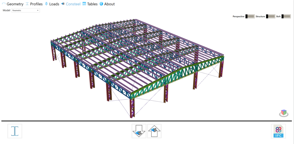
Following the initial successful collaboration, the second version of the tool, developed this year, includes the capability to retrieve available analysis and design results from Consteel. This enhancement allows the tool to prepare data sheets that include material lists for both beams and bolts, as well as internal forces, thereby facilitating the joint design process.
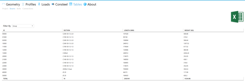
All the tables can later be exported to Excel sheets, while the structure itself can be exported to an IFC model. These functionalities were developed using a range of exceptional third-party plugins, with Pangolin being the primary tool for creating the actual structural model. Additionally, HumanUI was employed to create a smooth user interface that can be effectively utilized even without specific Grasshopper knowledge.
We believe this project serves as a prime example of harnessing not only Pangolin’s inherent potential but also a wide range of open-source applications within the Rhino/Grasshopper community. However, achieving such successful outcome requires an investment of mainly time to delve into computational design. Even with just one dedicated individual, remarkable results can be achieved, thereby expanding the toolbox of an entire team. Consequently, we eagerly anticipate the emergence of more similar projects in the modular, product-based segment of the construction industry.
Every year, different strategies are influencing how Consteel‘s features are developed. In 2023, our primary focus is on one key subject: making the software easier to use. Accordingly, almost all of our new developments aim to increase usability across our software. Novelties include practical functions for efficient model manipulation, easy modification, and providing clear information not only in Consteel but also in Descript and in our cloud-based platform, Steelspace too. The new features are summarized here below.
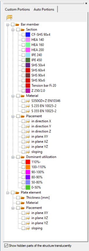
Automatic model portions
The existing model portion function is an easy way to handle larger models and it’s been used by all of our customers during their workflow for years. Studying the created model portions made it clear that there are some common categories used for portioning the structural models which are used very frequently by our users. Based on that, we have developed a new, automatic model portioning function beside the manual model portion. This feature creates automatic model portions grouping the members by the following categories: cross-section, material, placement, and utilization for bar members; and thickness, material, and placement for plate elements. The auto portions are always updated reflecting the actual state of the model and can be used together with the manually created custom portions.
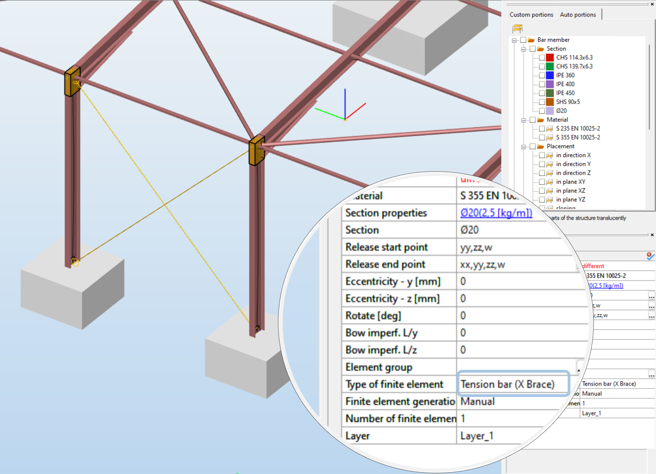
X Bracing members
The tension-only members are usually used for bracing purposes arranged in X shape. The specific nonlinear behaviour of these pairs of members can cause troubles in the linear calculations (first order analysis, linear buckling or vibration analysis) while it can be handled in other analysis types using some nonlinear solution technique. The new development allows the user to set the finite element type of these members to X Brace, which handles the problematic analysis types with the usual linearization technique and automatically leaves these members out from the second order matrix compilation.
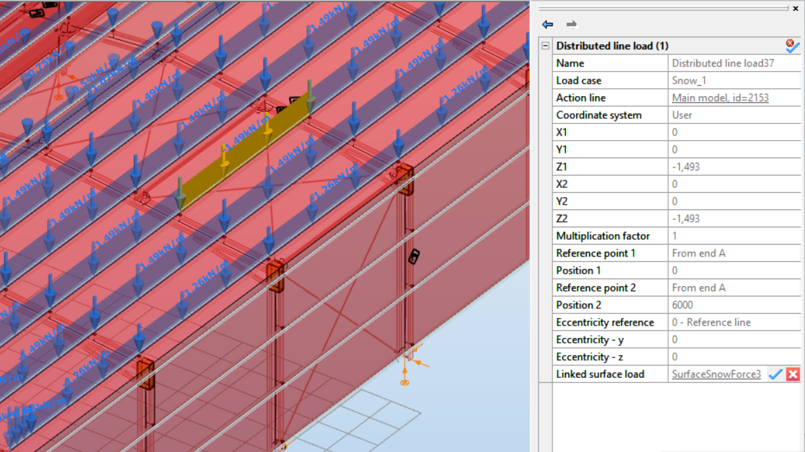
Load transfer surface improvements
The use of load transfer surface is an easy and efficient way to distribute surface loads to bar members. But since it is not a real mechanical process, the distribution can not always yield the expected solution (for instance can not consider the stiffness of the surface). To handle this problem we have modified the basic operation of the load transfer surface allowing the user to edit the properties of the generated line loads once unlinked from the surface load. The automatic update (regeneration of the line loads) function can also be controlled by the user.
Extended and unified design results
Sometimes, you may need a quick review of the calculation results, while other situations may call for a more in-depth examination. In order to satisfy both requirements, we have completely reworked the handling and visualization of the design results. Firstly, the ULS and SLS design checks are unified in terms of execution and result display. Accordingly, all the dominant design results can be instantly accessed considering any limit states. On the other hand, all the utilizations from all load combinations are saved and shown for more detailed investigation of the structural adequacy.
New environment for software interactions
Reacting to the ever-growing demand for interaction possibilities between software, we have developed a new concept to operate as the background for all of our interfaces. The SDK-based environment creates the possibility to translate the external models to a general format (smadsteel) compatible with Consteel and Steelspace also. As a first step on our way with this methodology, a plugin for Axis VM structural analysis software is developed. Axis VM models can be converted to smadsteel format and then opened in Consteel. The conversion is extended to mechanical objects (supports, releases, etc.), loads and load combinations as well, not only geometry and sectional properties. The environment includes tools for cross-section and material conversion at different levels, and a comprehensive report of the import including visualization of the problematic objects in the model.
Descript language developments
As our built-in script environment is used more and more often, new development needs constantly arise during applications in different areas. These needs usually require new elements and improvements in the scripting language to cover the required functionalities. The novelties include new commands such as custom cold-formed cross-section creation, object referencing queries, and more, plus expanded capabilities in object creation, manipulation, and querying, all designed to empower your civil engineering projects with unmatched versatility and efficiency.
Improvements for efficient modeling (user requests)
In response to direct requests from our valued customers, this version also incorporates several enhancements aimed at further improving Consteel’s usability:
- hiding of selected objects
- separation of copy and move functions
- bulk material modification for steel cross-sections
- highlighted start and end points for structural members
- quick select by property directly from the property tree by double-click
- structural member selection from analysis and design result tables
Detailed model comparison
A model undergoes numerous modifications during the design process. Thanks to previous Consteel innovations, we can now preserve important milestones and decision points related to changes in the form of model version histories. Building upon this foundation, we have further enhanced the capability to compare versions in model histories. The new functionality allows users to customize the comparison process, focusing solely on objects and attributes that are relevant. The comparison results vividly illustrate parameter differences, highlighting the designated objects and attributes. Within the user interface, elements such as the selection tab and object property display have been redesigned to facilitate easy access to the differences in data between both versions during the comparison.
Introducing the Clipping Plane feature in Steelspace
Discover more about your model! With the latest enhancement in the cloud-based Consteel model viewer, Steelspace, we’re introducing a powerful feature – the clipping plane. This innovative tool allows you to create a clipping plane object, representing a plane that clips away parts of the geometry within a specific viewport.
Improved collaboration management
Effective collaboration is often key to accelerating work, particularly in the structural design phase of larger projects. In recognition of this, we’ve taken steps to enhance collaboration within Consteel and improve the Model version history feature. With our latest development, you can grant access customized with different permission levels to your model to multiple engineers or team members. In this, case more engineers can save new versions into the model history of the same project where the versions include now the creator as well.
Watch our comprehensive guide on the new version
In this comprehensive video, we walk you through a step-by-step workflow guide, demonstrating how to leverage Consteel 17 to its full potential.
Explore the new features for free
Download the new version now!
DownloadIf you are new to Consteel, you can explore the new features easily. After the release of Consteel 17, the new developments will be automatically available in our free trial version.
Our users who use our software with online protection will automatically have access to the latest version after installation. Consteel users with USB dongle protection will receive the necessary information to upgrade when the new version is released. For any problems with the update, please contact our support team.
The ordinary practice of structural design is based on the use of many empirically introduced safety factors and statistical approaches, considering / applying different standards. As a result, the geometrical model of the buildings and the loads acting on them can often differ significantly from reality because of these simplifications, especially if the geometry of the structure is freeform, which is practically impossible to accurately model and analyse with standard tools.
Detaching from reality can be a legitimate concern for a structural designer which amplifies when it comes to wind load evaluation. Thoughtfully, but structural engineers must be able to respond to the needs of today’s architecture. This is why computational fluid dynamics (CFD) simulation methods are increasingly appearing as an alternative solution for the challenges of non-conventional geometries between the conservative solutions offered by the standards and the experimental way, using wind tunnel tests. For this purpose OpenFOAM as a CFD engine offers a wide range of solutions. Although, for these type of simulations a proper environment is essential, where one can easily define all the necessary parameters to setup a flexible simulation case. This led us to begin the implementation of these solutions into our platforms based on our research in the topic. This lead to a new functionality, where one can define the simulation parameters conveniently, using OpenFOAM as the engine without a comprehensive knowledge regarding its use.
Design code interpretations in the case of free-form structures
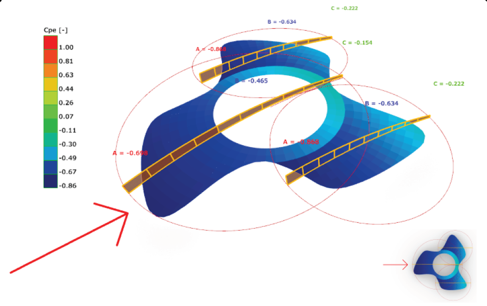
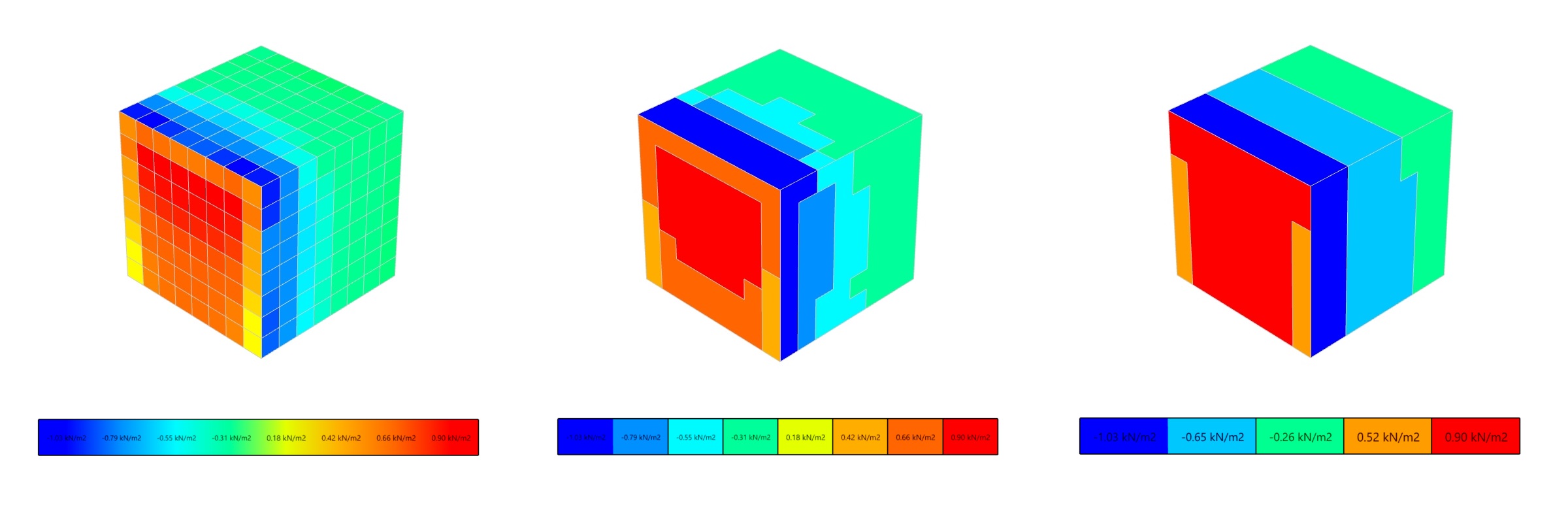
The effect of the wind acting on a structure can be calculated from the average wind speed and the fluctuating wind speed generated by the turbulence around the building. EN-1991-1-4 defines the wind-generated effects as simplified surface pressures for the calculation of wind loads acting on structures, considering the shape of the structure, its location, the roughness of the terrain, etc. Thus, the wind loads can be considered as a quasi-static external pressure equal to the effect of the turbulent wind with maximum speed. Then the effective surface pressure (or suction), can be determined as the result of the product of the peak pressure (at “z” height above the ground) and the pressure coefficients belonging to the building, according to the design codes, which are covering only a few regular shapers: flat roofs, different pitched roofs, vaulted roofs, domes, etc.
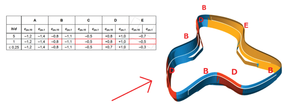
For instance, for the free-form structure below to determine these external pressure coefficients could be really challenging. First of all, due to the relatively low roof slope of the structure, it is difficult to decide whether to consider the roof as a flat roof with curved eaves or as a dome (due that it fits to the surface of a sphere). In the case of a dome, the standard gives 3 characteristic values in a relatively cumbersome way, depending on the eaves height, roof height and diameter of the building. Applying these values to the geometry is highly debatable, especially at the edges.
Similar questions are raised if we try to apply the pressure coefficients on walls which are not regular.
CFD Simulations
Computation Fluid Dynamics is a branch of fluid mechanics that deals with the numerical simulation and analysis of fluid flow and heat transfer phenomena. CFD involves using computer algorithms and numerical methods to solve the governing equations of fluid flow, such as the Navier-Stokes equations, on a discretized domain containing finite element volumes. For these problems OpenFOAM as a toolkit is one of the most suitable.
OpenFOAM contains several applications which can be divide to two main types. Solver-type applications are suitable for solving specific solid or liquid body mechanical problems, while the Utility-type can be used for mesh creation and data management.
To prepare a CFD-based simulation, the following main steps can be identified:
- Preliminary mesh generation processes to create a model suitable both for simulation and load definition
- Define input parameters (wind speed, vp(z) corresponding to the peak value of the wind pressure,wind direction, roughness length z0, boundary conditions, etc.)
- OpenFOAM finite volume mesh generation (define refinements, castellated mesh and snap controls etc.)
- Turbulence model and solver definition (domain initial conditions, run controlling etc.)
The current stage of the development uses only one specific turbulence model, that handles the partial
differential equations of the kinetic energy and the energy distribution rate (k-ε model), with
the solver simpleFoam (SIMPLE = Semi – Implicit Method for Pressure Linked Equations) . In this
scenario, the simulation assumes the following conditions:
- Incompressible, rigid bodies
- Turbulent flow
- No physical time, quasi-static pressure
Our service as a general workflow for wind load evaluation
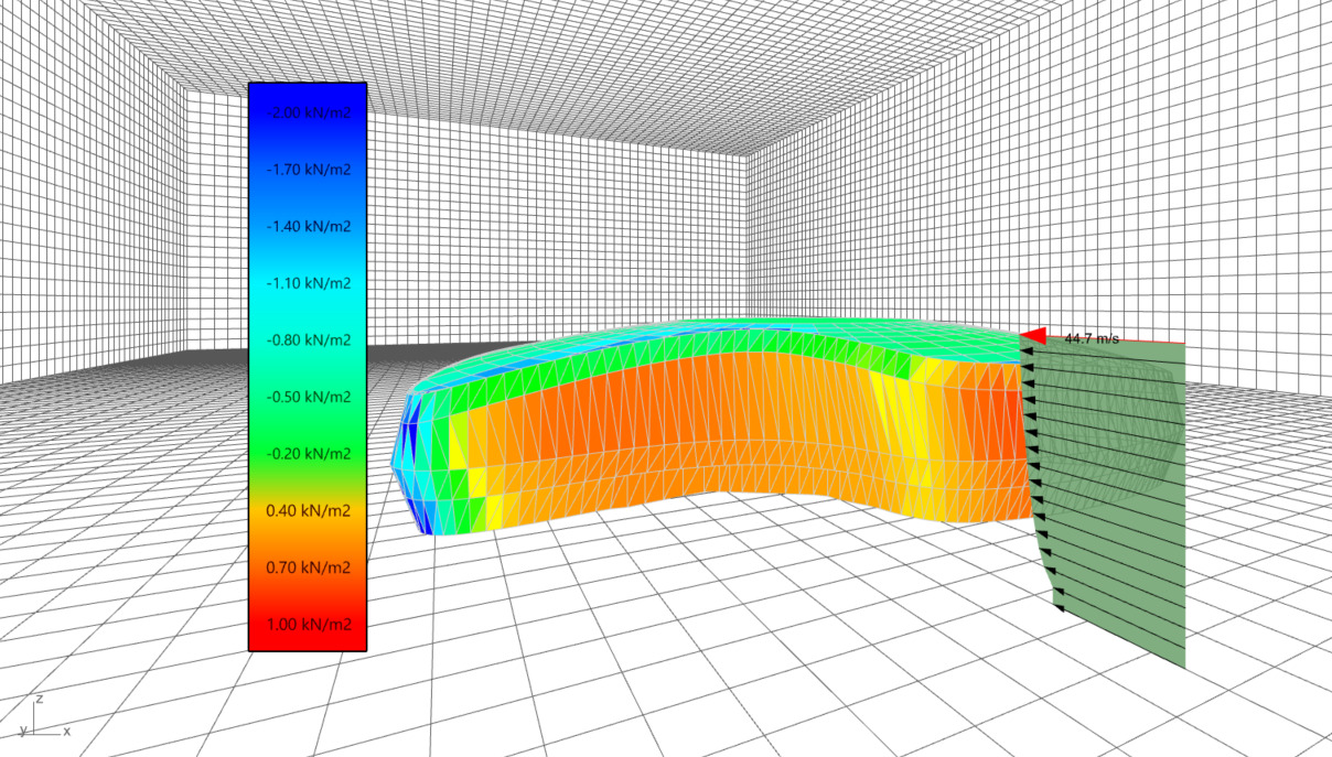
According to the steps we identified above we began the development of a service which as automatically as possible creates a premesh for load assignment and prepares the necessary data for OpenFOAM, which generates a finite volume mesh ( preprocess stage) and performs a simulation ( dataprocess stage) as shown below. For this, beyond the geometrical and meshing information, suchs as the cell size of the desired loads and the refinement, the user should provide only the wind reference base speed, the direction and the terrain category to define a wind profile according to the civil engineering logic (primarily the Eurocode wind profile corresponding to the peak velocity pressure).
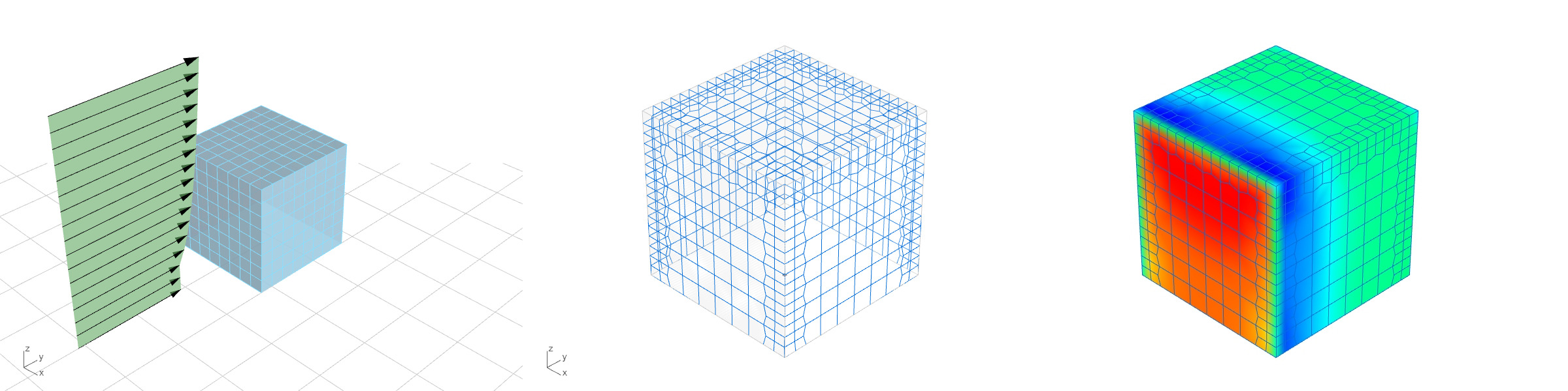
The current development aimed an additional and in the same time the main feature ( postprocess stage) which offers an automated conversion from the resulted pressure values to usable surface loads according to the users preferences. It will be possible to directly assign the simulation results to the premesh, or to apply a zoning logic, similar to the standard.
In conclusion, a serious potential can be observed in the feature, mainly due to its versatility. However, experience shows that although CFD can be used to perform wind load simulations for industrial use, its pertinence is highly dependent on the quality of the input parameters. So a minimal fluid dynamic expertise is still required, but the current state of the development already offers a solution for the structural engineers, in order to create these simulation relatively easily. The service is planned to be implemented in multiple channels using our existing platforms: Consteel (direct desktop use on Consteel models), Steelspace (cloud based use on compatible models) and Grasshopper (use on any models defined in the GH environment for instance with Pangolin) to make it available for as many engineers using different tools as possible.
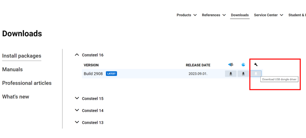
A new driver is available on our website at Downloads for the USB dongles.
A new driver is available on our website at Downloads for the USB dongles. It is compatible with the latest updates of Windows 10 and 11 too. Please download and install it to ensure flawless operation of your dongle! Only users who use Consteel with an USB dongle protection will need this driver.
How to download the new driver?
Log in to your account on our website and click on the USB driver download icon to download the driver. Then you just need to install it to your computer.
Discover an in-depth case study detailing the expansion of a Turda, Romania plasterboard factory, which shows how the expansion led to the construction of nine new structures. This project, which uses a central parametric model, won third place in this year’s The Steel Lion Award 2023 competiton, thanks to its innovative use of Consteel software for steel structural design and Pangolin, the Rhino-Grasshopper plugin for Consteel.
1. Project Info
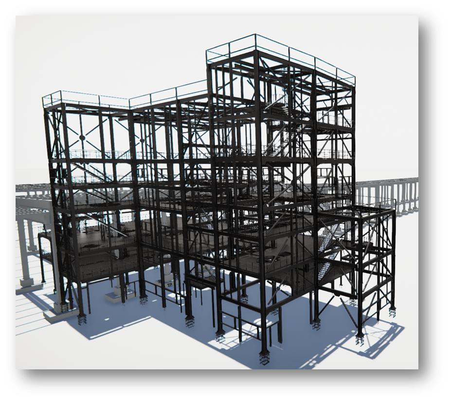
The aim of the project is to expand an existing plasterboard factory in Turda, Romania, resulting in the creation of 9 new structures.
These buildings serve various purposes, from raw material processing to waste storage. The building that monitors and serves the manufacturing process is called the “mill,” constructed from a multi-storey rigid steel frame structure. The maximum frame span is 8 meters, and the total height of the 7-story structure is 28 meters.
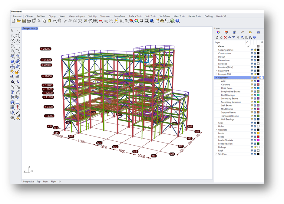
2. Central parametric model
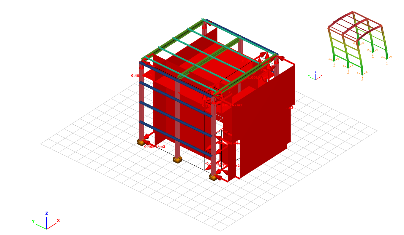
While the geometry of the structure is based on classic shapes that may not necessarily require parametric design methods, our goal was to parameterize and create a central BIM model to keep all data in one place during the project’s design process. This data includes 3D models of the technological equipment, technical data sheets, and plans related to them, along with permanent and live loads, all revisions, architectural plans, and more. Given the data provided, we constructed the geometry, defined the loads, and other relevant information. The resulting structure was a complete wireframe model, and its global static analysis was performed using Consteel.
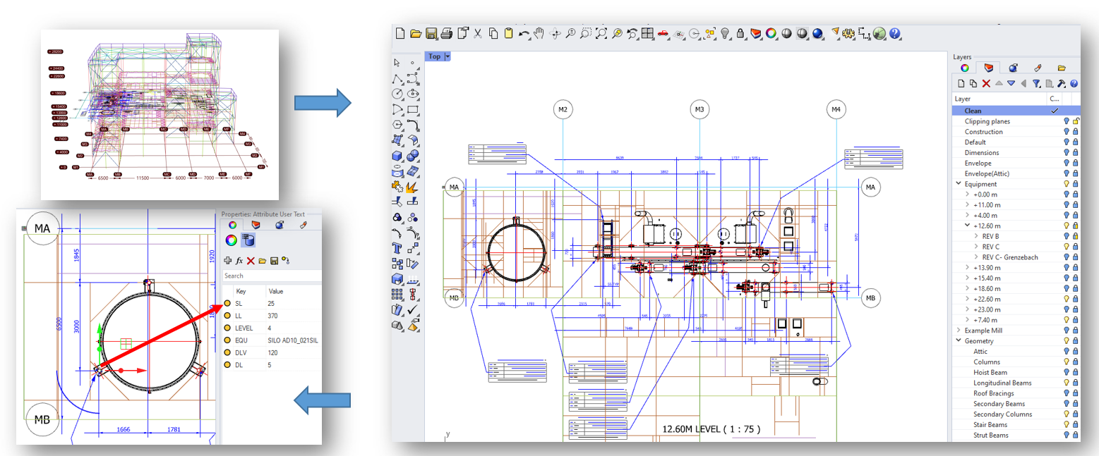
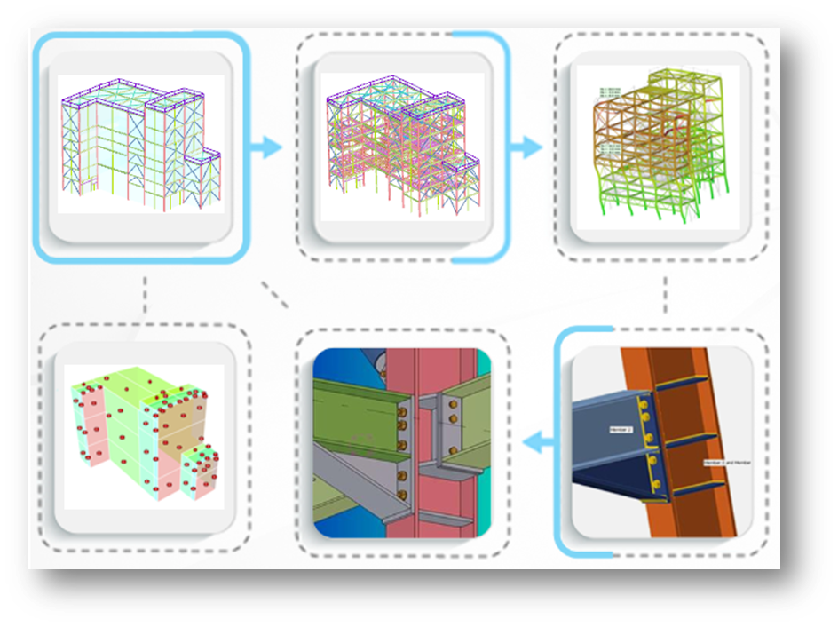
In this way, the centralized model controlled the entire design process from Rhino-Grasshopper interfaces (top-left corner). From here, the complete load evaluation process was coordinated (bottom-left), the construction of the structural model (top-center), the generation of models required for joint calculations (bottom-right) based on the results of the structural analysis (top-right), and ultimately, the whole detail design (bottom-center).
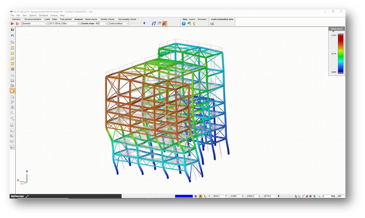
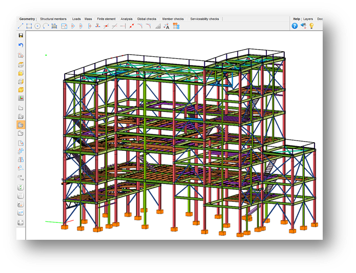
3. Analysis in Consteel
The primary challenge in the design was harmonizing the technology with the structure. Essentially, the design of the technological equipment occurred in parallel with the design of the structure, and the structure had a subordinate role throughout the whole process, necessitating flexibility to adapt to any modifications from the technology side. Within Consteel, we continuously optimized the structure, and utilizing Pangolin’s bidirectional functionality it allowed us to update our centralized model almost instantly. This ensured that the current state was always available, enabling concurrent detailing of the building. Another challenge was that the building was connected to a precast concrete production building. For the affected facades, the ordinary bracing system couldn’t be applied on the first three levels, significantly affecting the structure’s global behavior under horizontal loads. Therefore, it was crucial to consider all structural elements within a global model, in this case, together with the trusses providing the necessary horizontal rigidity.
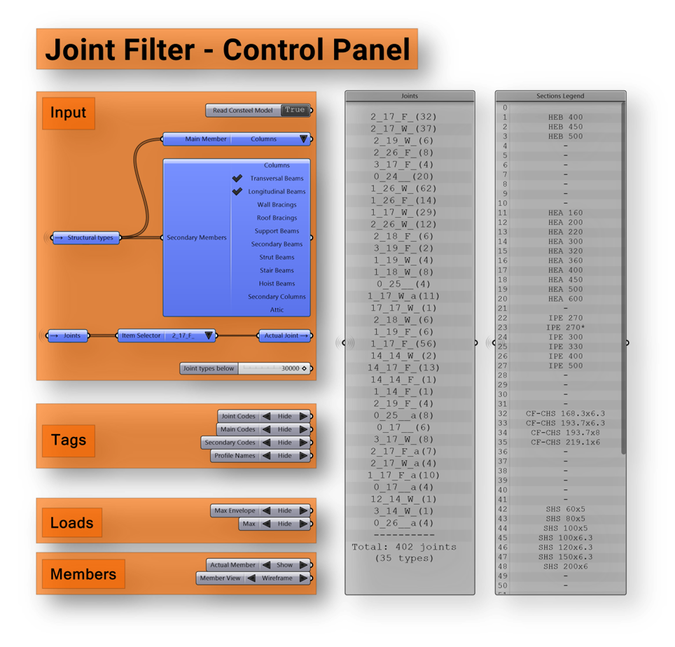
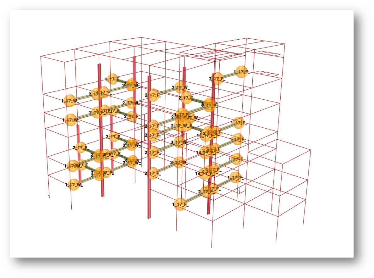
4. Joint Filtering
Following the main structural analysis, we performed joint analysis using the Grasshopper-IdeaStatica compatibility. This allowed us to filter out type joints (e.g., column bases, column-to-beam connections) from the Consteel model, which were then dimensioned for the internal forces collected automatically. These forces, while considering all possible positions for the selected type joints, represented the maximum concurrent and the absolute maximum values. Using predefined Tekla macros, we distributed the dimensioned connections to all positions with the help of Grasshopper. This method enabled the scattering of 2074 joints on the strut beams with a single click. Using this approach, we distributed over 3800 Tekla macros under Grasshopper control.
5. Conclusions
The design process consisted of two main phases. During the conceptual design phase, which served as the basis for the final authorization plans, we began writing scripts based on a parametric central model. We handled this as an internal development, which could also serve as a starting point for similar projects in the future. Thus, by the time we were creating final detailed plans in the second phase, we had a highly flexible tool at our disposal, providing data for structural checks, global and joint dimensioning, detailing, and ultimately for drawings. This workflow proved to be extremely efficient, requiring only one project lead structural engineer and one engineer responsible for script development and usage throughout the roughly two-year design process from the steel structure perspective. Therefore, when everything was considered final, we were able to involve an additional five engineers, and together, we completed the joint dimensioning, the remaining manual detailing, and the manufacturing design in approximately two months.
This month we have shared 4 new example models regarding fire resistance, cold-formed macro sections, user-defined cross sections, and shear stiffness. Models are available for download from the Knowledge Base.
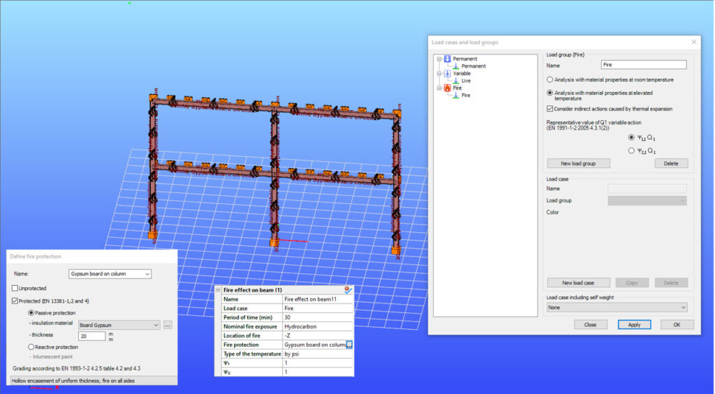
Perform structural analysis at room and elevated temperatures as part of design process for fire resistance
Did you know that you could use Consteel to perform structural analysis at room and elevated temperatures as part of design process for fire resistance?
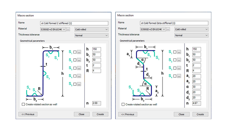
Include in your model a wide range of cold-formed macro sections
Did you know that you could use Consteel to include in your model a wide range of cold-formed macro sections?
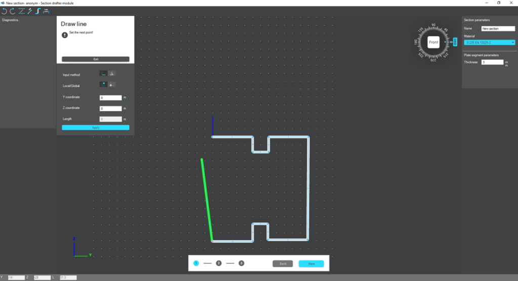
Draw a user-defined cross section and calculate its section properties
Did you know that you could use Consteel to draw a user-defined cross section and calculate its section properties?

Consider the shear stiffness of a steel deck as stabilization for steel members
Did you know that you could use Consteel to consider the shear stiffness of a steel deck as stabilization for steel members?
To see what else the Consteel software can do, check out the features.
From now, it is faster, easier, and more convenient to contact Consteel support, as the application form is now available directly from Consteel. The new development also allows users to send ideas or reach learning materials while working in Consteel. Let’s see this feature more in-depth.
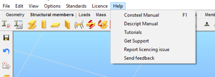
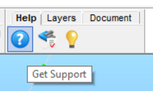
Extended Help menu
We have extended the top Help menu with different options according to your needs. The menu has been divided into two sections, the first includes links to the Online Manual, to the Descript Manual, and to a filtered selection of our Knowledge Base with tutorials and guides. No need to login to our website as it will be done automatically through Consteel if you use it with online protection.
The second section is for support-related requests. The “Get Support” command opens our Support system notification window to ask for help issues regarding Consteel. If you have trouble with licensing then you will need to click on the “Report licensing issue” command. We would like to hear your ideas regarding Consteel as well, so if you have any feedback, click on the “Send feedback” command and share your thoughts with us! Your email address will fill in automatically.
The new Help tab
We have implemented a new “Help” tab for the essential support-related requests into the graphical interface to make posting support issues more convenient.
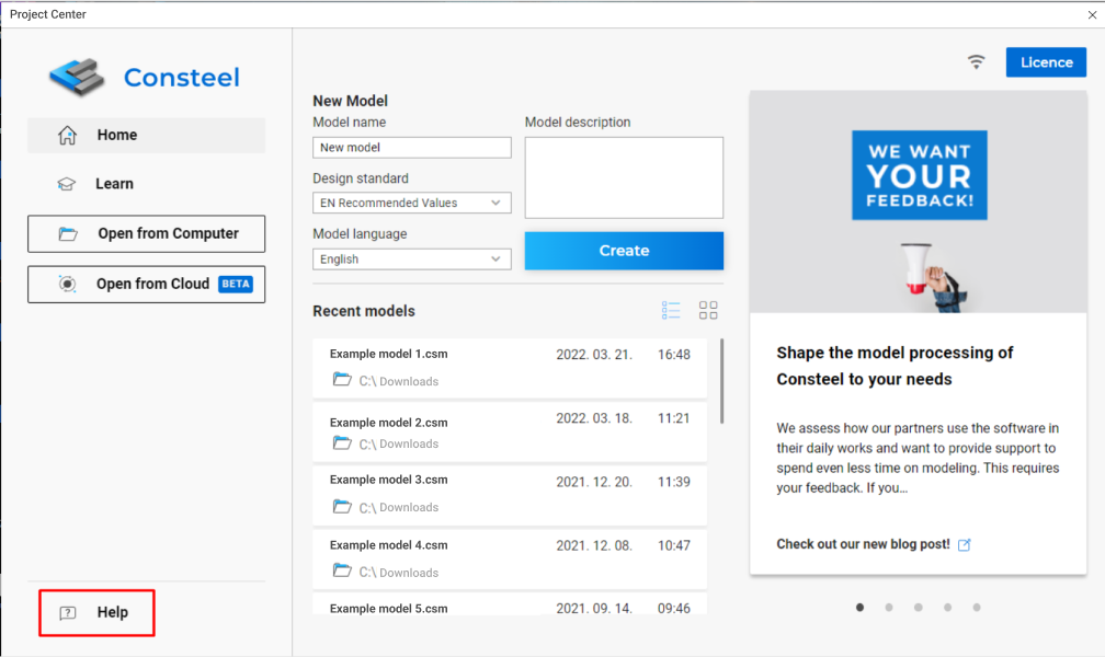
These support options are also available from the left bottom side of the Project Center.
When you open a new support request, report a licensing issue, or request a feature, please add as much information as you can, so we can help you more effectively. If you are facing any issues, attach your Consteel model and screenshots to your request as well. If possible, please always include the version number of the Consteel you are currently using.
We hope you find our development useful. This feature is available for users with Pro or Premium memberships. Feel free to get in touch with us as we only can be better if we hear your feedback.
We assess how our partners use the software in their daily works and want to provide support to spend even less time on modeling. This requires your feedback. If you want to take part in shaping Consteel, fill out our 10-20 minutes questionnaire and be part of our updates.
We would like to better understand how our users use Consteel during modeling and their thoughts about the software’s graphical interface. Your answers will help us to make the development of Consteel better and understand your experience.
The survey should only take 10-20 minutes and available in the following languages: English, German, Spanish, Polish, Greek, Romanian, Hungarian. Filling the survey is voluntary and anonymous.
The survey is closed thank you for your time.