Did you know that you could use Consteel to perform dual analysis with 7DOF beam and/or shell elements?
With two advanced features, Superbeam and Convert members to plates, you can choose the approach that best suits your project needs, whether you’re focused on modeling efficiency or detailed analysis.
The Superbeam function offers a smart, adaptive way to handle structural members. It enables you to model with the simplicity of standard 7DOF beam elements while allowing you to switch to a more detailed shell-based analysis for specific members whenever needed.
Once the structure is modeled using beam elements, you can select how each member is analyzed:
- Using the beam model, which applies Consteel’s proven 7DOF beam elements along with its comprehensive design tools.
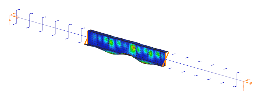
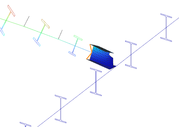
- Or using a shell model, which is automatically generated for selected members. This shell model includes detailing features such as web cutouts and stiffeners, fully integrated into the global analysis model.
This dual approach is fully adaptive. You can continue modifying your model using beam elements and switch between analysis modes as required, offering both speed and precision within the same workflow.
For a complete overview of how to activate and manage Superbeam functionality, refer to the documentation:
Superbeam – Consteel Manual


When you need complete control over geometry and mesh, or when shell analysis alone is not sufficient, Consteel provides the Convert members to plates function. This tool allows you to manually transform selected members into actual plate elements, enabling detailed modeling from the start.
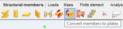
Unlike the automatic conversion used in Superbeam, this method performs a permanent, non-reversible transformation (though undo is available during the session). It supports a wide range of section types, including hot-rolled, cold-formed, and welded profiles.
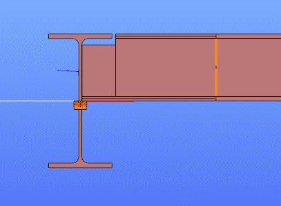
The conversion process preserves and adapts existing connections, eccentricities, loads, and supports. Where needed, rigid bodies and constraint elements are added to maintain structural continuity. These constraints ensure proper transfer of deformations, including warping, between the new plate model and the rest of the structure.
This function is especially useful in cases where precision is critical, such as modeling joints, fabrication-specific details, or complex load interactions.
To learn more, see the full guide here:
Convert Members to Plates – Consteel Manual
Both Superbeam and Convert members to plates serve different purposes, depending on the level of detail and control required in your model:
| Feature | Superbeam | Convert members to plates |
| Workflow | Beam modeling with optional shell analysis | Full plate modeling from the beginning |
| Conversion | Automatic and reversible | Manual and permanent |
| Suitable For | Flexibility in analysis, quick modeling | Full control, high-detail requirements |
| Supported Sections | Welded I and H profiles | Hot-rolled, cold-formed, and welded sections |
| Detailing Support | Cutouts and stiffeners (in shell analysis) | Full geometric detailing, including transitions |
| Design Integration | Integrated with beam-based design tools | Suitable for fabrication-level modeling |
In Superbeam, constraint elements are generated automatically to connect converted shell elements to other members, such as bars. During member-to-shell conversion, these elements link the FE shell nodes to the rest of the model, ensuring accurate deformation transfer.
If the convert members to plate function is applied directly to beam elements, rigid bodies are created at their ends, which is useful for analyzing local behavior but does not transfer warping deformations. If the beam is first converted to a shell and then to plates, hinged rigid edges are placed along the plate boundaries. This arrangement, combined with constraint elements, transfers not only in-plane and out-of-plane deformations but also warping between the shell and the rest of the structure.
Download the example model and try it!
Download modelIf you haven’t tried Consteel yet, request a trial for free!
Try Consteel for freeClick the button bellow to download and read the full article at page 187-195.
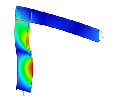
In this paper a numerical study is presented which examines a steel frame with two different finite element programs. Stability failure is more frequent in a lot of cases than strength failure hence it is important to focus on these failure modes: global, in-plane-, out-of-plane -, lateral-torsional- and local buckling. Three models were used with different elements such as shell elements and 7 DOF beam elements. 7 DOF beam elements were used in the first model, shell elements were used in the other two. The first of the shell models gave too much local buckling shapes therefore it was improved with local constraints and that is the third model where global buckling shapes can be examined. There are three different procedures to calculate the resistance: (i) the general method, (ii) the method of the reduction factors, and (iii) the simulation. The analysis results of the different programs and design methods were compared to each other and to the manual calculation based on the Eurocode 3 standards.
gate