Did you know that you could use Consteel to build 3D models with smart link elements which automatically adapt the model when profiles are changed?
Link elements are used to connect members that are not directly joined. In Consteel, three types of link elements are available: Link, Smart Link, and Constraints.
A smart link is a dynamic connection element designed to simplify the management of geometric changes between connected members. It automatically follows the movement, rotation, or profile changes of the primary member it is attached to, while also ensuring that any connected secondary member adapts accordingly.
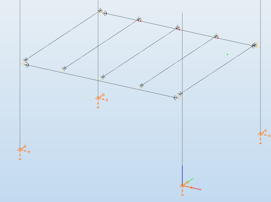
A common application is connecting a main beam to a purlin or other secondary elements, with smart links positioned at specific points. They enable easy attachment of additional members while preserving the defined eccentricity, and automatically adapt to any changes in the main beam’s geometry or profile.
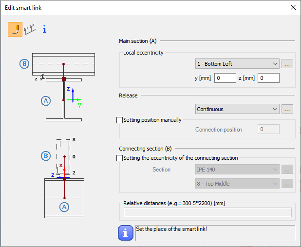
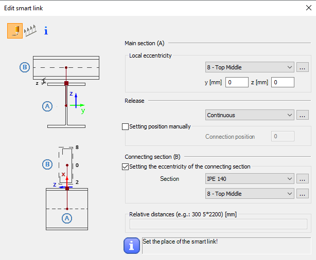
The Smart Link function, located on the Structural Members tab, opens the Edit Smart Link dialog box after activating the command. This allows you to:
- define the eccentricity of the link relative to the main section
- set the connection type in the Release field
The connection position can be specified manually or left to default automatically to the edge of the main member.
Defining the connecting section is optional. When specified, an eccentricity can be assigned, and the program automatically determines the link length based on the section height and reference point.
Smart links can be placed individually by clicking on a member or in groups by specifying distances from the member’s start. Any placement conflicts are indicated by a warning.
By combining associative behavior with precise control, Smart Links support efficient and reliable 3D modeling in Consteel. They help maintain structural intent throughout design changes, reduce manual corrections, and improve overall model consistency.
For workflows where geometry evolves and secondary members must remain accurately connected, Smart Links provide a clear advantage and enable a more resilient and adaptable modeling process.
Download the example model and try it!
Download modelIf you haven’t tried Consteel yet, request a trial for free!
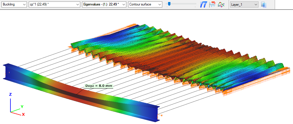
Try Consteel for freeDid you know that you could use Consteel to Consider the shear stiffness of a steel deck as stabilization for steel members?
Download the example model and try it!
Download modelIf you haven’t tried Consteel yet, request a trial for free!
Try Consteel for free
Introduction
Are you wondering how a web opening would influence the lateral-torsional buckling resistance of your beam? Check it precisely with a Consteel Superbeam based analysis
It is often required to let services pass through the web of beams. In such cases the common solution is to provide the required number of opening in the webplate. Such an opening can have a circular or rectangular shape, depending on the amount, size and shape of pipes or ventilation or cable trays.
Beams must be designed to have the required against lateral-torsional buckling. The design procedure defined in Eurocode 3 is based on the evaluation of the critical bending moment value which provides the slenderness value, needed to calculate the reduction factor used for the design verification.
There is no analytical formula provided in the code for beams with web openings. Would the neglection of such cutouts cause a miscalculated and unsafe estimation of the critical moment value?
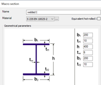
The following demonstration will be made with a 6 meters long simple supported floor beam with a welded section.
Exposed to a linear load of 10 kN/m, the critical bending moment value of the solid web beam can be obtained by performing a Linear Buckling Analysis (LBA) with Consteel.
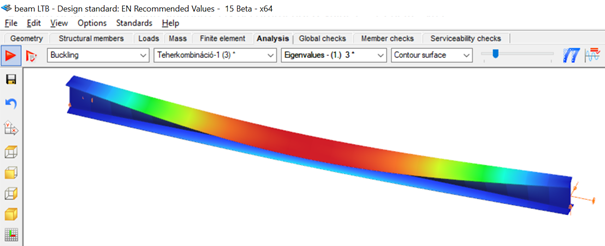
The obtained critical multiplier for the first buckling mode is 3.00 which means that the actually applied load intensity can be multiplied by 3.00 to reach the critical load level. The corresponding critical moment will have the value of Mcr = 3.0 * 47.18 = 141.54 kNm yielding a slenderness of 1.286 (Mpl,Rd = 234.20 kNm) and a lateral-torsional buckling resistance of 0.394 * 234.20 = 92.27 kNm. With this value the actual utilization ratio is at 51%.
How would this value change if a rectangular opening needs to be cut into the web of this beam?
Analytical formula for critical bending moment
By looking to the analytical formula (ENV 1993-1-1 F.4) to calculate the critical moment of double symmetric sections loaded at eccentric load application point it becomes obvious that the section properties having effect on the moment value are Iz, Iw and It.
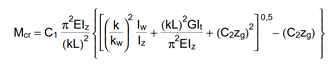
An opening in the web has no effect on the first two values and has very little effect on the last one. As it has been already shown in previous article, the presence of such an opening can have effect on the vertical deflection, but as long as the lateral stiffness of a beam is much lower than it’s strong axis stiffness, the vertical deflections can be neglected when the lateral-torsional buckling resistance is calculated. The usual linear buckling analysis (LBA) performed also by Consteel neglects the pre-buckling deformations.
Therefore one can expect that in general web openings can be disregarded when the critical moment value is calculated.
Analysis with Consteel Superbeam
Beam finite elements cannot natively consider the presence of web openings. In order to obtain the precise analysis result, it is possible to use shell finite elements. The new Superbeam functionality comes as a solution in such cases. Instead of using beam finite elements, let’s use shell elements!
Opening can be positioned easily along the web, either as an individual opening or as a group of openings placed equidistantly. The opening can be rectangular, circular or even hexagonal. Circular openings can be completed with an additional circular ring stiffener.
The rectangular opening for this example can be easily defined with this tool. As there is no need to provide any additional opening on the remaining part of the beam, only the first part which includes the opening will be modelled with shell elements and the rest can still be modelled with beam finite elements. Using this technique, the total degrees of freedom of the model can be kept as low as possible. When using Superbeam, the designer has the choice whether to use beam or shell finite elements, as appropriate.
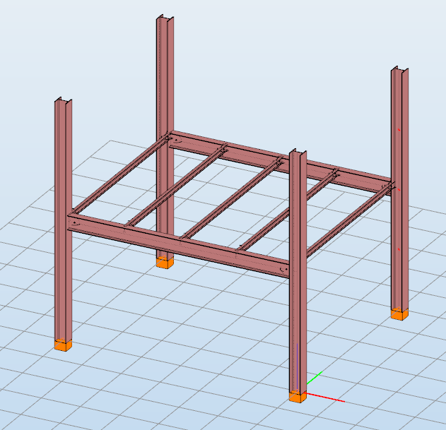
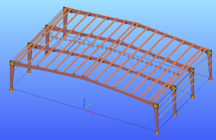
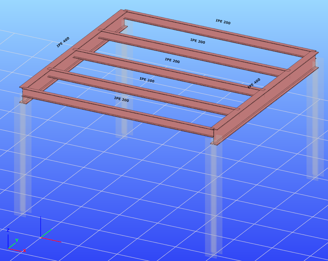
gateExample hall model for trying the smart link feautre in Consteel

Watch our user guide about How to use the smart link feature to learn more.
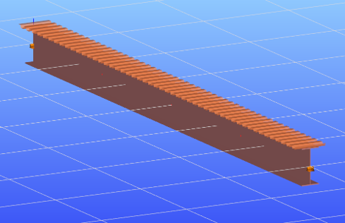
gateExample model for trying the smart link feature in Consteel
Watch our user guide about How to use the smart link feature to learn more.
gateIntroduction
In the last years, freeform architecture became more and more popular. A variety of complex geometric shapes are used for the facades of buildings, which brought the demand of new, innovative tools and solutions for modelling of these structures too. In Consteel we have developed such functions to make the engineers‘ work easier.
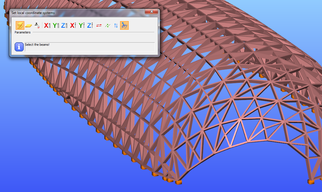
Section orientation
Orientation of the sections is always a problem. We have implemented a tool, with which the rotation of the sections can be done automatically. Sections can be rotated perpendicularly to the surface of the freeform shape of the structure. Z axis will be perpendicular to the surface formed by the connecting beams.
Load transfer surfaces
Covering a freeform structure with load transfer surfaces -like in the picture below-manually, would take a lot of time and effort. Our tool for multiple load transfer surface placement gives you a quick, easy and effective solution for covering your freeforms.
gateIntroduction
The Frame corner wizard is a useful additional function for modelling and analyzing the corner region in order to consider its special behavior.
What is it for
The frame corner zones have usually significantly different behavior than the beam elements connected to each other without significant angle between their reference line. Frame corner wizard recognises the corner regions and applies special methods during modelling, buckling analysis and global checks. Using this function will provide very similar analysis results compared to where the frame is modelled with shell elements.
But in order to that, the topology of the frame corner must be defined by the user. Four different types can be chosen. The 7. DOF displacement is transferred differently in every case. To learn more technical details of the frame corner types, please see our user manual.
How to use it
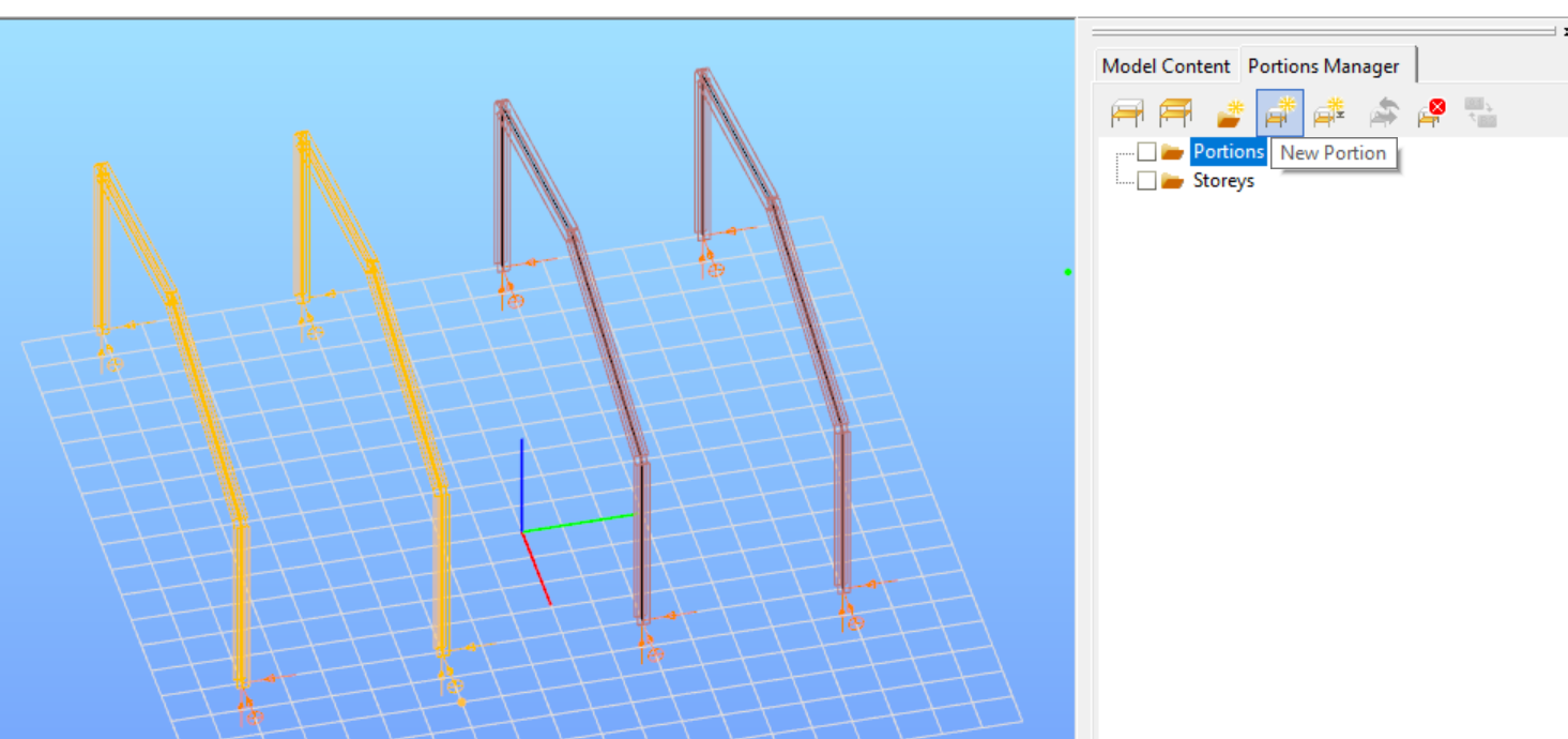
At first define Portions of the model containing all the structural elements you intend to connect with the same type of corner topology.