Consteel Joint vs. Fictive Joint
If you’ve ever wondered why there are so many joint types available when using the 'Create Joint by Model' function in Consteel, and when each type should be used, this article provides clear explanations directly from the developers.
Introduction
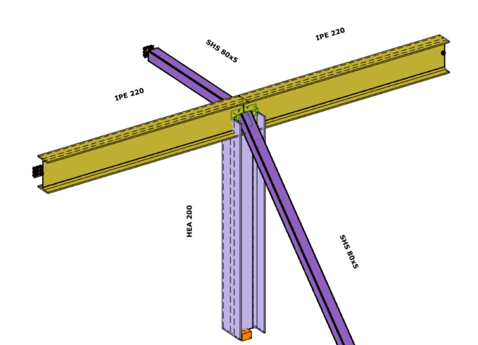
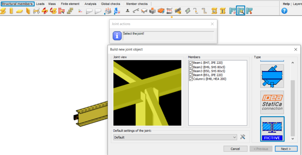
The process starts by selecting intersecting members using the 'Create Joint by Model' option under the Structural Members tab. It’s important that at least two members intersect so that a connection can be defined. Once selected, a window appears with a list of available joint types on the right. The list is dynamic and depends on the selected members. For instance, if the joint does not meet Eurocode standards, Consteel Joint connection types will not be displayed.
Consteel Joint
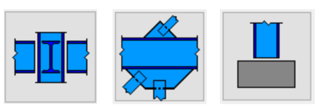
Consteel Joints are ideal for standard, Eurocode-compliant connection designs. When using the same 'Create Joint by Model' feature, depending on the selected elements, users may see multiple Consteel joint types. These can include connections like beam-to-beam joints with or without a main element, bracing connections that require the user to select the primary structural element, or column base joints, which can also be accessed via the spread footing tool.
Fictive Joint
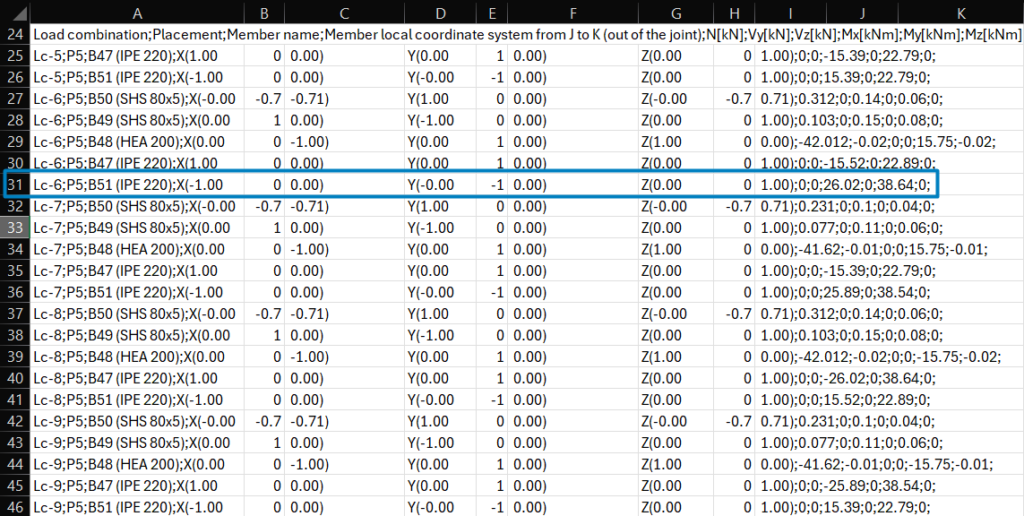
The Fictive Joint is particularly useful in collaborative design workflows where multiple teams or companies contribute to the structural design or when engineers decide to design the connections in their traditional way, using, for instance, handmade Excel spreadsheets. In such cases, specific joints may be designed externally, but all the necessary data is collected from the Consteel model and can be exported to a .csv file, Excel-compatibile format. This typically includes information such as placement, member names, local coordinate directions from J to K, internal forces and moments according to all analyzed load combinations.
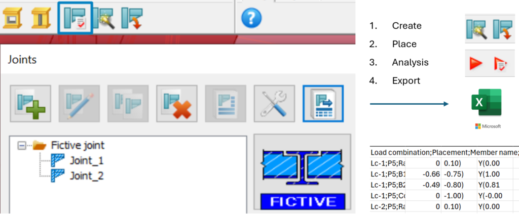
Using Fictive Joint, users can easily place the required joints in the model, categorize them according to type, and export all necessary data into a .csv file, Excel-compatibile format. It is important to note that data can only be collected after the Fictive Joints have been placed and the analysis has been run.
The Fictive Joint collects internal forces from each position where it is placed, streamlining communication with external design teams. If the structure is modified, it updates automatically after reanalysis, saving time and avoiding redundant work.
Make sure to export the .csv file after the final changes have been made.
Why choose Consteel Joint?
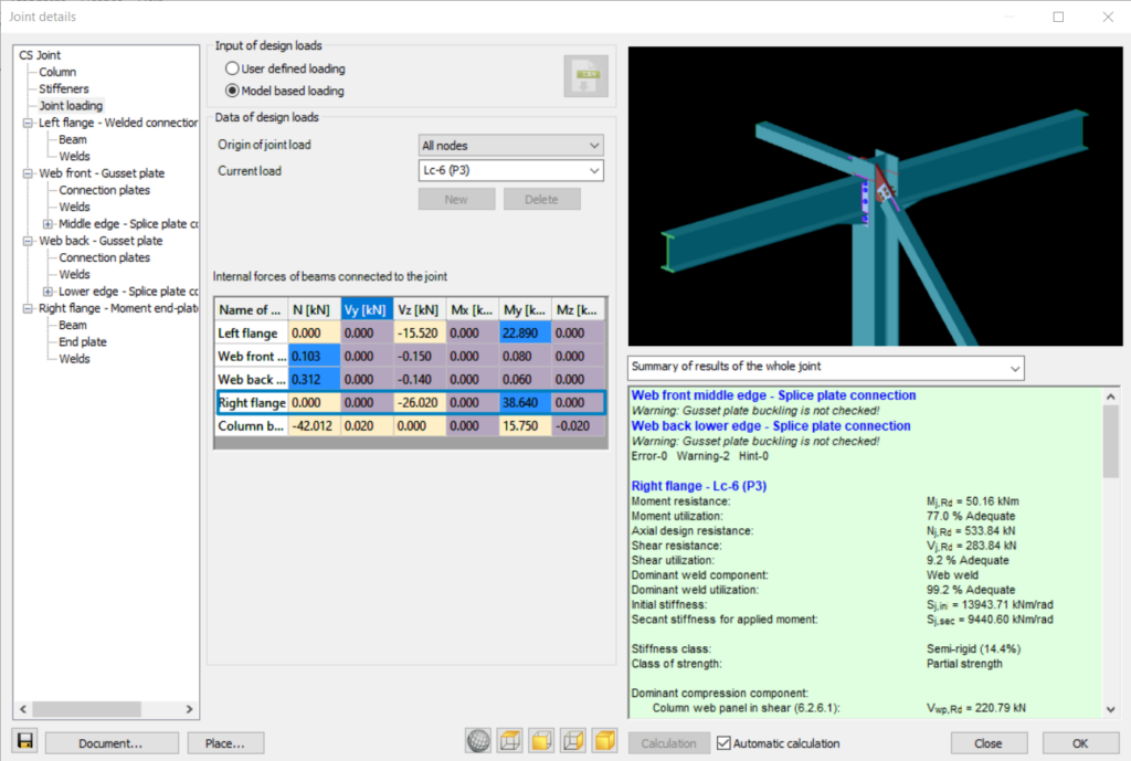
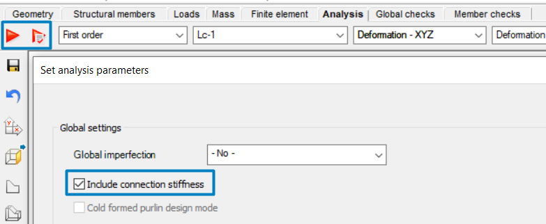
One of the biggest advantages of Consteel Joint is its full integration within the software. There’s no need to install additional plugins or manage separate licenses. The tool automatically uses all the modeled data—such as geometry and applied loads—making the process straightforward and efficient, accounting for all internal forces directly from the model, where it is placed. Another key benefit is that when joints are designed and placed directly in the model, their stiffness can be included in the overall 3D structural analysis. This results in more accurate and realistic calculations.
When to use Fictive Joints instead?
However, it’s important to note that Consteel Joints are only applicable for standard connection types. For special joints, where Consteel cannot perform the design, the Fictive Joint offers a flexible and practical solution for identifying, organizing, and sharing the necessary information with others.
Conclusion
In summary, Consteel Joints offers a powerful, integrated solution for standard connection design, while Fictive Joint is an essential tool for managing custom or externally designed connections. Understanding the purpose and capabilities of each will help you streamline your workflow and collaborate more effectively within complex design projects.