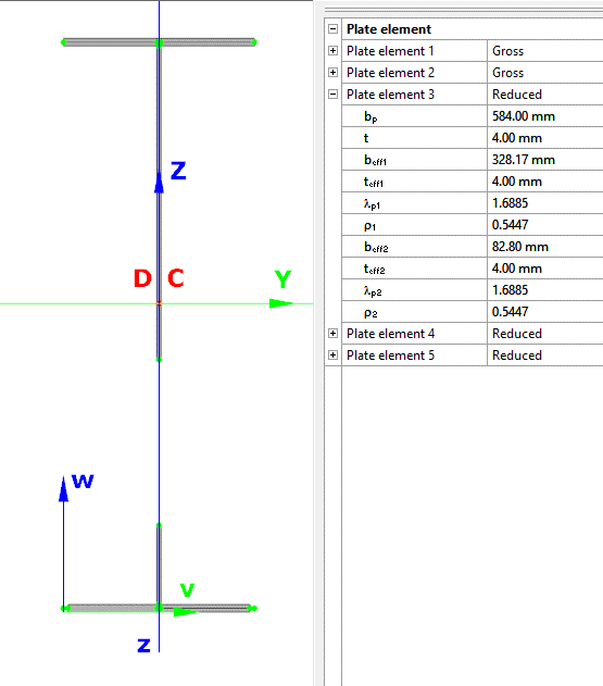
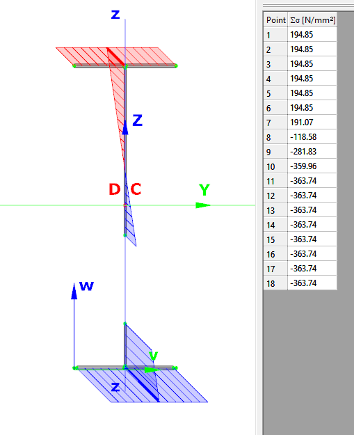
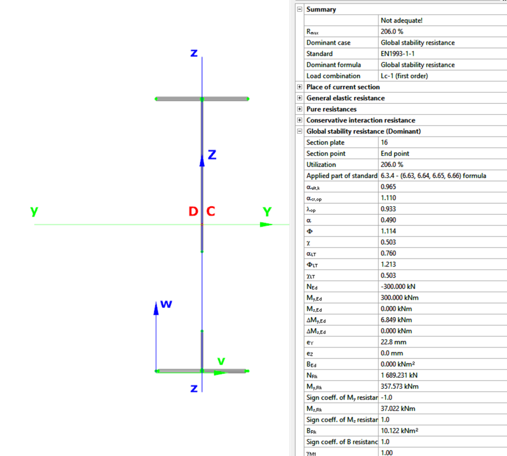
Did you know that you could use Consteel to calculate effective cross-section properties for Class 4 sections?
Download the example model and try it!
Download modelIf you haven’t tried Consteel yet, request a trial for free!
Try Consteel for free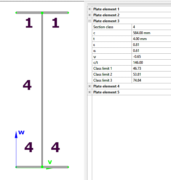
Did you know that you could use Consteel to Consider the shear stiffness of a steel deck as stabilization for steel members?
Download the example model and try it!
Download modelIf you haven’t tried Consteel yet, request a trial for free!
Try Consteel for free
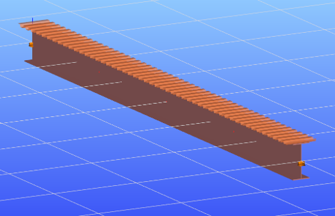
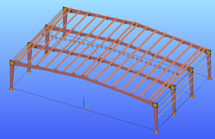
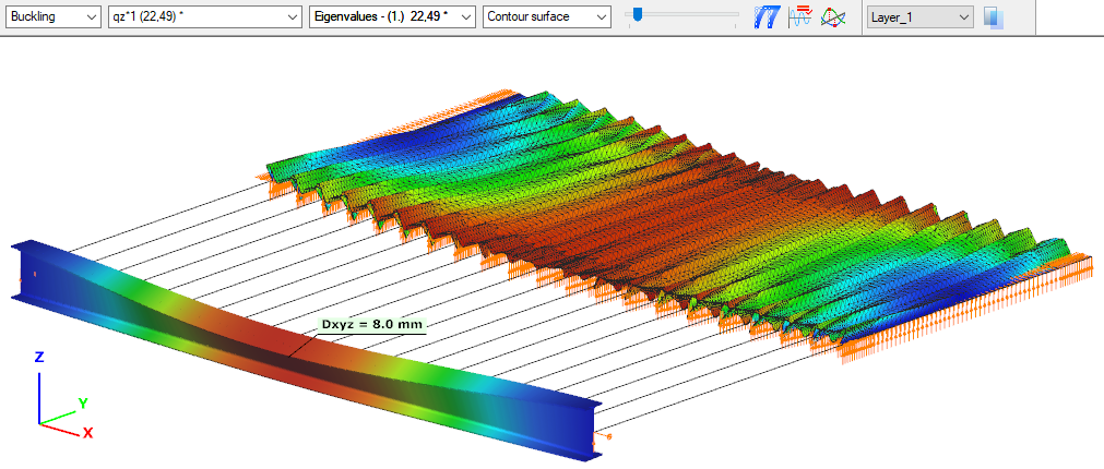
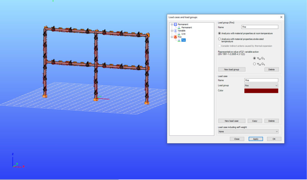
Did you know that you could use Consteel to perform structural analysis at room and elevated temperatures as part of design process for fire resistance?
Download the example model and try it!
Download modelsIf you haven’t tried Consteel yet, request a trial for free!
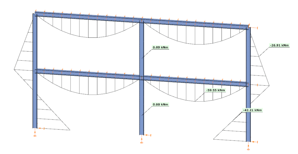
Did you know that you could use Consteel to calculate the elastic critical moment of a member subject to arbitrary loading and boundary conditions?
Calculating the elastic critical moment can quickly become difficult when beams have tapering, unusual restraints, or complex loads. Consteel simplifies the process and gives a quick, accurate result for any situation.
The elastic critical moment for lateral-torsional buckling is the theoretical bending moment at which a beam, free to sway sideways and twist, becomes unstable and buckles elastically, before yielding, representing the absolute upper limit of elastic stability for beam bending. It depends on: cross-section stiffness properties (Iz, Iw), material (E, G), span / buckling length, restraint to lateral displacement and to warping at the restraints, and on the shape of the moment diagram (via factors C1, C2, C3).
For doubly symmetric I- or H-sections with constant cross-section, uniform bending, and classical boundary conditions, the elastic critical moment Mcr can be calculated using the analytical formula:

However, for arbitrary support conditions and loading scenarios, the calculation becomes significantly more complex, and the classical formula is no longer applicable. In such cases, specialized software such as LTBeam or Consteel is required.
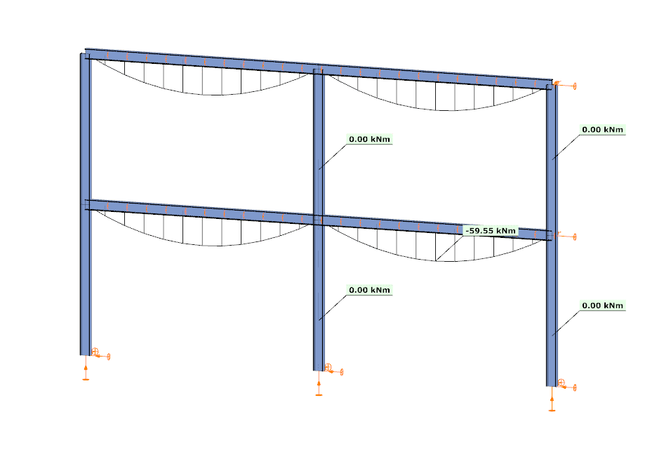
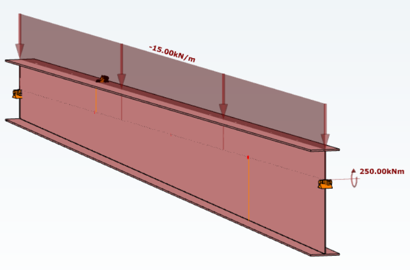
Let’s consider a tapered, welded I-section with pinned supports at both ends and two intermediate restraints, one at the bottom flange and one at the top flange. In addition to the uniform distributed load, a bending moment is applied at one end of the beam.
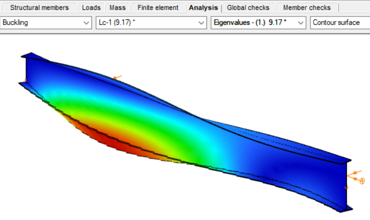
By performing a buckling analysis in the Analysis tab, the buckling shapes and the critical load factor (αcr) can be obtained. The elastic critical bending moment of the beam can be then calculated by multiplying the critical load factor by the maximum bending moment.
Consteel uses seven-degree-of-freedom finite element that fully accounts for tapering effects, torsion, and warping, key components in accurately capturing the true 3D behaviour of steel members. The seventh degree of freedom represents cross-sectional warping, which becomes visible in the buckling shape as the flanges move out of the plane of the cross-section.
Download the example model and try it!
Download modelIf you haven’t tried Consteel yet, request a trial for free!
Try Consteel for freeConsteel offers a range of load combination filtering options, which can be applied based on limit states, load cases, and analysis and design results. By applying different series of filters, designers can streamline their workflow and reduce calculation time.
Filtering options
Filtering is realized through the Load combination set definition window.
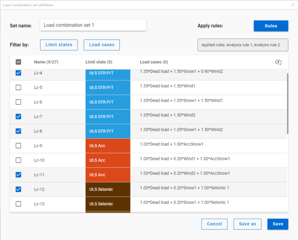
Filtering by limit states and by load cases are handled together with the checkboxes under the Limit states and Load cases buttons.
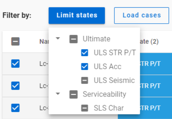
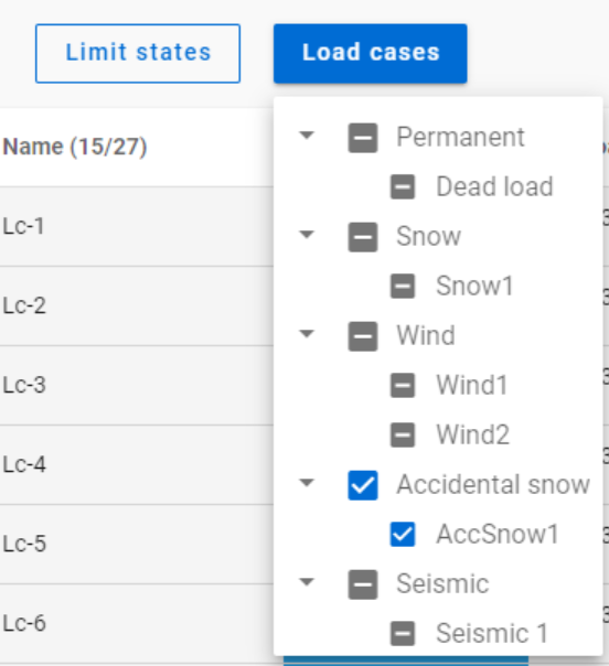
The 3-state checkboxes affect each other as they are not only used for selection but also for indication of the content. They can be manually set only to checked or unchecked. The middle state only appears when other filters are applied.
Filtering by limit states or load cases does not require any calculation results.
Filter by rules, on the other hand,is based on the actual analysis and/or design results. Different types of rules can be applied one by one or at the same time to select the desired load combinations.
When a rule is applied, all the load combinations that are selected on the Load combination set definition dialog- either with filtering by limit states/load cases or checked in manually- are examined at every position the rule indicates. Load combinations that meet the rule’s criteria are selected (remain checked in), while those that do not, become unchecked.
- With analysis rules, load combinations can be selected based on deformations or internal forces at either every finite element node or only at the member ends. This last one is included specifically for connection design. Deformations are checked in SLS combinations, internal forces are checked in ULS combinations only.
- With buckling rules, those ULS load combinations can be selected which have the elastic critical load factor (first buckling eigenvalue) less than the given limit.
- With design rules, load combinations can be selected based on utility ratios checked in every finite element node of the chosen portion. Utilizations are available from several design checks: dominant results and detailed verifications for steel elements such as general elastic cross-section check, pure resistances, interactions and global stability. Only ULS combinations can be filtered with design rules.
Interaction of the different filter types
Filtering by limit states, load cases, and rules can be used together, with rules being applied only to load combinations that are checked in and have the necessary calculation results.
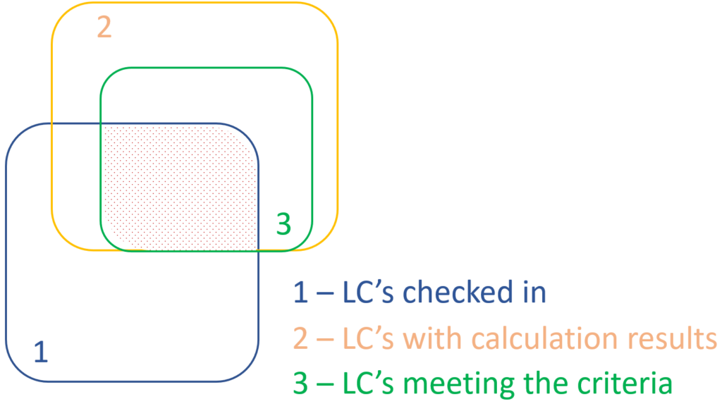
Let’s see an example.
It is a simple 2D frame model, with 27 load combinations of various limit states generated. Analysis and design results are calculated for all load combinations.
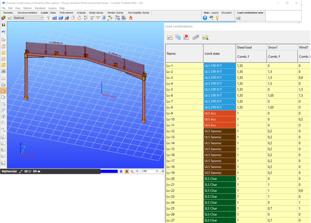
If applying design rule to select only those load combinations which result dominant utilization over 50%,

4 load combinations will be selected (Load combination set 1):
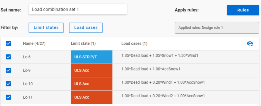
But if ULS Accidental limit state is turned off before applying the same 50% filter,
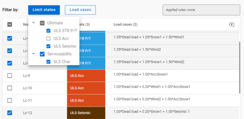
only one load combination is selected (see Load combination set 2).

Application of multiple rules
Applying multiple rules together results in the sum of the lists that would have been created separately.
gateTeil 1: Unterschiede bei der Stabilitätsausnutzung
Der Eurocode EN 1993-1-1 bietet grundsätzlich zwei Verfahren für den Stabilitätsnachweis von Stäben an:
(1) basierend auf Abminderungsfaktoren (Knickkurven) und
(2) basierend auf äquivalenten (eigenformaffinen) geometrischen Imperfektionen.
In diesem Artikel wird untersucht, wie sich diese beiden Methoden in Bezug auf die endgültige Stabauslastung Im Vergleich verhalten. Der Einfachheit halber betrachten wir nur eine einfache zentrisch beanspruchte Druckstütze, die auf Biegeknicken versagt. Für Fall (1) wird Kapitel 6.3.1 verwendet, während für Fall (2) angenommen wird, dass die Imperfektionen die Form der zum ersten Eigenwert gehörenden Knickfigur annehmen, und das entsprechende Kapitel ist 5.3.2 (11).
Offensichtlich sollten diese zwei Standardverfahren die gleiche Ausnutzung für das gleiche Problem ergeben. Dies ist jedoch im Allgemeinen bei weitem nicht der Fall.
GateGewöhnlich zeigt traditionelle baustatische Software die Verformungen von Balken mit ihren Querschnitten auf der verformten Schwerachse. ConSteel 15 dagegen benutzt eine fortschrittliche Methode für Deformationsdarstellungen, die feiner und realistischer ist. Natürlich sind die numerischen Ergebnisse identisch, aber mit der verfeinerten Visualisierung kann das 3D-Verhalten der Balkenstruktur besser erkannt werden.
Comparison of chosen methods for estimation of critical lateral torsional buckling bending moment of web-tapered I-beams. In this article, the elastic critical bending moments of the web-tapered I-beams calculated by the analytical and numerical solutions developed last years by researchers involved in the topic were compared with own calculations carried out with available common tools. The main goal was to verify the accuracy and convergence of the results provided by different modern methods and different finite bar elements 1D with 7 degrees od freedom at the node (7DOF).
Click the button bellow to download and read the full article. (PL)
gateConsteel 14 is a powerful analysis and design software for structural engineers. Watch our video how to get started with Consteel.
Contents
- Set analysis parameters
- Perform first and second order analysis
- Perform buckling analysis
- Analysis results in graphics and in tables
- Results: deformation, internal forces, reactions
This article aims to cover the theoretical background of the shear field stiffness determination methods implemented in Consteel. Modeling with the shear field stiffness based method will also be compared with shell modeling of trapezoidal deckings in Consteel.
Theoretical background
Modeling the shear stiffness of trapezoidal deckings is used to utilize their contribution to stabilizing the main structure. The possibility to consider the shear stiffness of sheetings is implemented at finite element level in Consteel and ensures easy modeling through its application onto beam elements.
Shear panel definitions
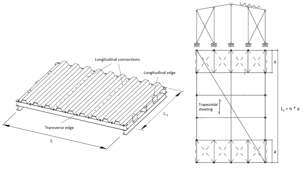
For the discussion let’s establish some basic definitions regarding shear panels.
- Dimensions:
- L [m]: width of the shear field, also the span of the stabilized beam
- Ls [m]: complete length of the shear field parallel to the ribs
- a [m]: effective shear field length for only one connecting beam element
- Stiffnesses:
- Gs [kN/m]: specific shear stiffness considering a 1 m long strip of an “Ls“ long shear field
- S [kN]: shear stiffness of the complete shear field
Determaination of the shear field stiffness
The general formula to calculate the shear stiffness in Consteel is the following:
There are 4 methods implemented in Consteel to determine the shear field stiffness:
- Schardt/Strehl method: (K1, K2), DIN 18807-1:1987-06 [1]

- improved Schardt/Strehl method: (K1, K2, K1*, K2* and eL)

- Bryan/Davies method: (K1, K2, K1*, K2*, eL, α1, α2, α3, α4)

- Eurocode 3: (1993-1-3 10.1.1 (10)) [2]

See in more detail here: Determination of shear field stiffness and application in Consteel
The first 3 methods are based on the 1. one, the Schardt/Strehl method. These methods operate on the same principle by calculating the shear stiffness from values (K1, K2, etc.) provided by the manufacturer of the sheetings. The 2. and 3. methods are more developed versions of the 1. one, trying to more accurately calculate the shear stiffness by introducing additional parameters to account for more sources of the overall shear stiffness of the sheeting.
The 4. method that is found in Eurocode 3 can be more generally applied since that doesn’t require such product specific values.
A basic assumption in case of these methods is that the sheeting is connected at every rib to the beams that it stabilizes (purlins in most cases). An additional modifying factor in case of all these methods is if the trapezoidal sheeting is not fixed at every rib, but every second rib, then the final “S” shear stiffness should be substituted by 0,2*S.
Theoretical background of the Schardt/Strehl method
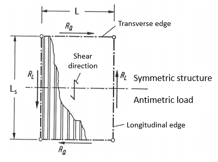
This approach is based on a model assuming a fully linear elastic behaviour of the diaphragm. The ultimate limit state is therefore defined by yielding in the corner radius at the flange-web transition. The mechanical model also assumes that the sheeting is fixed to the substructure at all 4 edges. Shear forces RQ and RL are acting on the sheeting at the individual fixed points on the lower flanges where the sheeting is screwed to the substructure. The number of waves in the sheeting is assumed to be large enough so that the individual forces acting at the transverse edges in the middle are assumed to be constant (n>10). The length “Ls” of the shear field can be arbitrary, but should be in reasonable proportion to the width “L” of the shear field (<4).
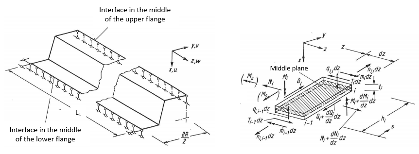
Based on these assumptions the mechanical analysis can be isolated to a half of one wave of the sheeting as shown on the left-hand side of the following figure:
On the right-hand side the considered internal forces are shown for one slice of the sheeting.
Assumptions for the mechanical model:
- The Ms and Mz moments are neglected (shown in brackets on the right-hand side figure).
- Transverse bending moments “mi” at the level of the plate are considered. These moments have a 0 value in the center of the lower and upper flanges.
- The longitudinal stresses σz are constant over the thickness “ti” of the plates and linearly distributed over the height “hi”.
- The flexibility of connections is neglected.
The method accounts for the following effects:
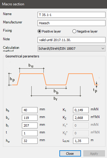
- Shear deformation: corresponding value: K1 [m/kN] shows the sheetings compliance coming from shear deformation. The lower this value is, the more stiffness the sheeting has.
- Warping deformation: corresponding value: K2 [m2/kN] shows the sheetings compliance coming from warping deformation. The lower this value is, the more stiffness the sheeting has.
Component considering shear deformation
The value K1 can be calculated from the following formula based on the properties of the trapezoidal sheeting:
where
- ∑l [mm]: Summed up length of all the plates within one full wave
- br [mm]: length of one complete wave
- G [N/mm2]: shear modulus
- tcore [mm]: structural thickness. (generally: tcore = tnominal – 0,04 mm)
The formula of the K1 value is similar to how it should be calculated in case of a planar plate, but its thickness corrected with the ∑l/br ratio, or in other words the ratio of the complete length of the plates to the length of one wave. The K1 shear deformation compliance value is directly proportional to the ∑l/br ratio, therefore if a certain trapezoidal sheetings height is increased with everything else left the same, the corresponding K1 value would increase, and the stiffness coming from shear deformation would decrease. On the other hand the K1 value is inversely proportional to “G” shear modulus and “tcore“ structural thickness, so if either of these values would increase, K1 would decrease, and the stiffness coming from shear deformation would increase.
Component considering warping deformation
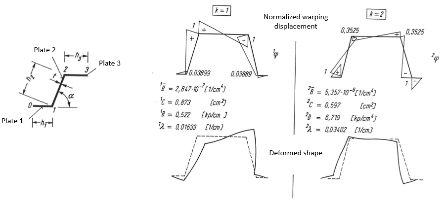
The K2 parameter further softens the structure taking into account the warping deformations. The detailed calculation of the K2 parameter will not be shown here due to its extensiveness and complexity. The details of this calculation can be found in the literature [5]. The calculation is based on the “Folded Plate” theory [8]. To obtain the K2 parameter the warping displacements and warping coordinates have to be calculated for the sheeting. The following figure shows an example for the normalized warping displacements and deformed shapes for k=1 and k=2:
k=1 and k=2 are connected to individual solutions for the differential equation system describing the mechanical behavior based on the “Folded Plate” theory.
Calculating shear stiffness
The behavior of the two components in the formula of the shear stiffness is different. The part that considers the shear deformation only depends on the effective width “a”, but independent from the total length of the shear field “Ls”. On the other hand the part that considers the warping deformation is also dependent on the total length of the shear field “Ls”. The K2 parameter in the denominator is divided by Ls, which means that the longer the total shear field is, the larger the specific shear stiffness is going to get because of the contribution of the warping deformations.
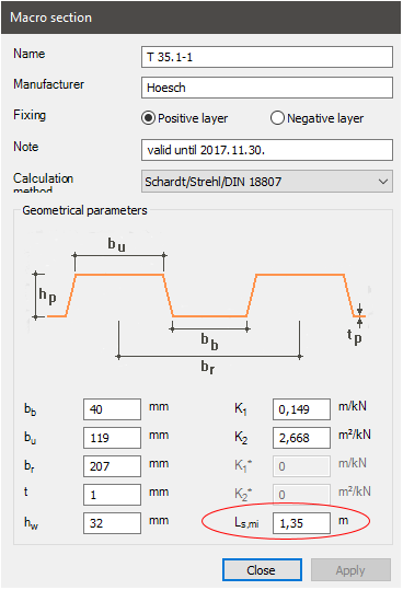
Also if the total length of the shear field “Ls“ would get really low, then K2/Ls would approach infinity, which means that the stiffness approaches zero. For this reason a minimal length for sheetings “Ls,min” is also provided by the manufacturers, which gives the specific shear stiffness “Gs” a minimum value.
Comparison against shell models
The effect of the shear stiffness of a trapezoidal sheeting can be modeled in multiple ways. In Consteel additionally to built-in shear field field object applicable on beam elements, the sheeting can be modeled directly with shell elements. This latter approach is more complicated and time consuming to set up, but should provide similar results. Such a comparison was prepared in Consteel.
Examined structure
Stabilized beam: IPE300 S235
Span: L = 4140 mm
Type of trapezoidal sheeting: Hoesch T 35.1
- Examined thicknesses: 0,75 mm; 1 mm; 1,25 mm
- Examined sheeting lengths: 2 m, 3 m
Horizontal line load: qy = 10 kN/m
The load and the trapezoidal sheeting are both acting on the centerline of the stabilized beam.
Consteel shear field model
In this modeling version the stabilizing effect of the trapezoidal sheeting is modeled by the shear field object implemented into Consteel.
Example figure: Ls = 2 m, a = 2 m, Gs = 3293 kN/m, S = 6586 kN
Consteel shell model
In this modeling version, the trapezoidal sheeting is modeled by shell elements. The thicknesses of the shell elements are equal to the structural thickness tcore. The model of the trapezoidal sheeting is included in a frame made from beam elements. The sheeting is connected to the frame by link elements at the lower flanges where the sheeting is screwed to the substructure. The frame is included in the model in order to connect the shell elements to the main beam. The beams of the frame have a cross-section that has relatively insignificant weaker axis inertia compared to the shear stiffness of the sheeting. The shell elements are connected through the frame to the main beam by link elements that only transfer force in their axial direction.
Example figure: Ls = 2 m, a = 2 m
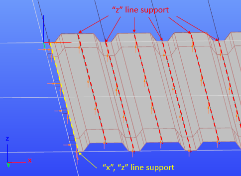
The shell elements are also supported in the vertical direction along the middle lines of its top and bottom flanges in order to eliminate the bending deformation resulting from the eccentric compression load on the sheeting, since the shear field model also does not take this effect into account. The edges on both sides of the sheeting are supported against “x” and “z” directional displacements in order to account for the sheeting being fixed to the substructure at all 4 of its edges. The line supports on the plate elements are shown on the following picture viewing the structure from below.

