When applying design rules in load combination filter, the most frequently used utilization type is Steel – Dominant results. What results are exactly considered by this option and what do corresponding limitations mean?
Introduction
There are four ways to apply load combination filter: based on limit states and load cases, manually, and by rules. Unlike the other three methods, filter by rules is only possible based on analysis and/or design results.
The most effective way to reduce the number of load combinations is definitely the use of design rules.
With design rules, load combinations can be selected based on utility ratios. Utilizations are available from several design checks, including dominant results and detailed verifications for steel elements, such as general elastic cross-section check, pure resistances, interactions, and global stability.
The meaning of the dominant check
The dominant check is not always the check which gives the maximal ratio but the one with the maximum RELEVANT ratio. Typical example: if plastic interaction formulas are valid, those results will be dominant over general elastic cross-section check results, although the latter are higher.
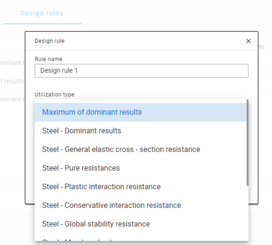
Steel – Dominant results
Steel – Dominant results option contains the utility ratio of the dominant check at every finite element node, in all load combinations. Meaning that there are as many utilization values as the number of load combinations calculated, in every FE node.
It is also important to understand the difference between the utilizations of Maximum of dominant results and Steel -Dominant results. Maximum of dominant results option contains the dominant utility ratio of the dominant load combination at every node, like an envelope of Steel-Dominant results. Meaning there is only one utilization value in every FE node. Also, it is the same as the dominant result table on Global checks tab.
When a rule is applied, the utilizations of the chosen utilization type are compared against the limitation. The load combinations which give the results that correspond to the limitation, are selected by the rule. Every FE node of the selected model portion is examined.
Limitations in case of Steel – Dominant results
- Maximum: to select the combinations which cause the maximum utilization at any node. It can be the same as Maximum of dominant results, except if there are combinations where the utilization is the same and it is maximal. In this case, here all the combinations are selected, while with Maximum of dominant results, there is always one maximum.
- More than % of maximum: to select the combinations as in ’Maximum’ plus those which cause utilization that is more than the given percentage of the maximum. E.g. at a certain point max utility ratio is 80%, Limitation= More than 90% of maximum. This rule will select all the load combinations which cause utility ratios between 0,9*80=72% and 80%.
- More than: to select the combinations which cause utilization more than the defined value at any point.
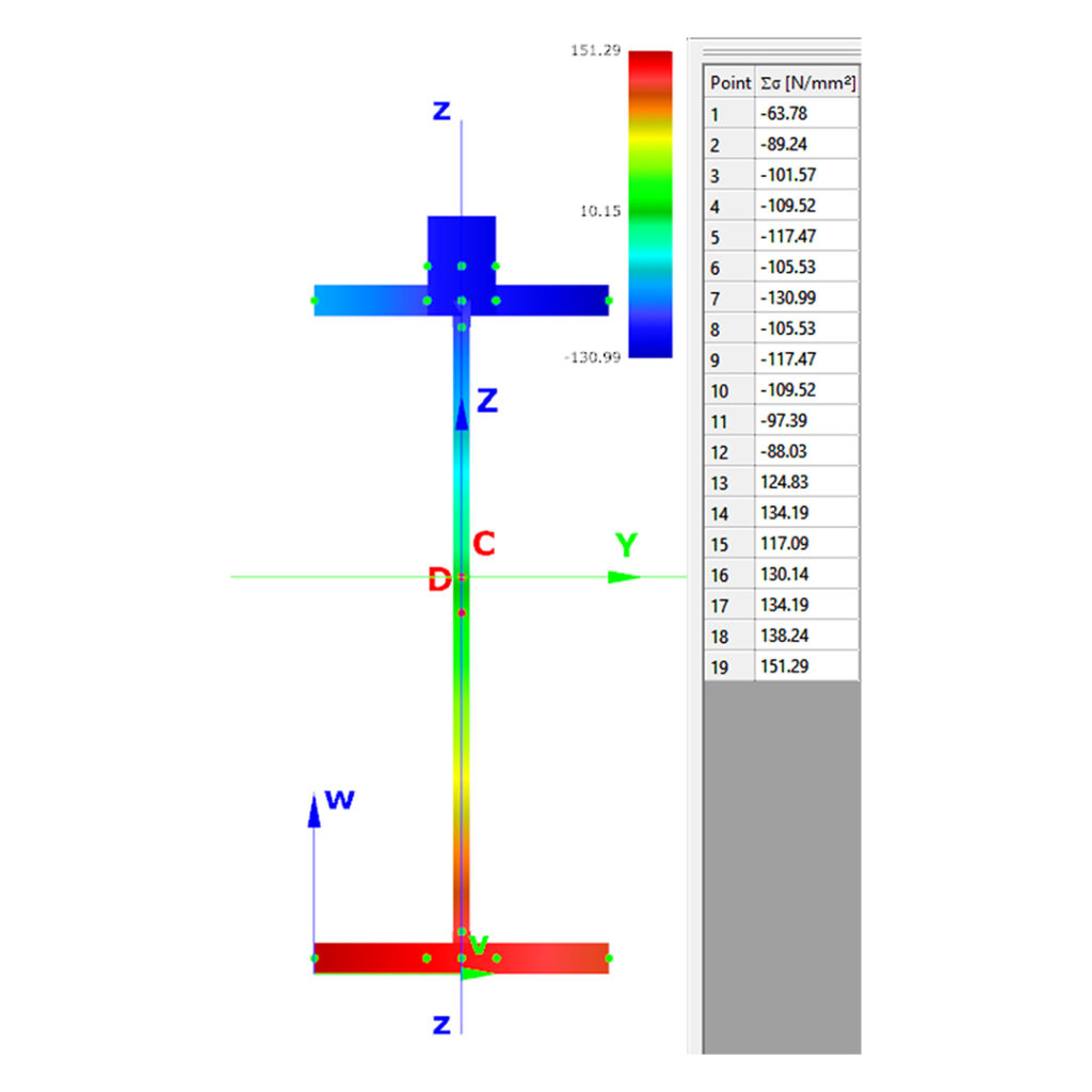
Let’s see an example of a simple 2D frame for better explanation. Right-side beam is in the portion for which three design rules were applied. Five points are selected for representation but of course all the nodes of the portion are examined against the rules’ limitations.
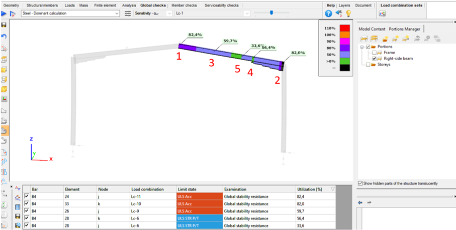
The utilizations of the five dedicated FE node in all 11 load combinations are shown on the below diagram. (To find all of these utilizations in the attached model, global checks must be calculated for the load combinations one-by-one.)
gateDid you know that you could use Consteel to include in your model a wide range of cold-formed macro sections?
For line member modelling, the cross-section must first be loaded into the model. In Consteel, there are four options to do this, either starting from the Section Administrator or directly during beam or column modelling: From Library, Macro Section, Draw Section, or My Library.
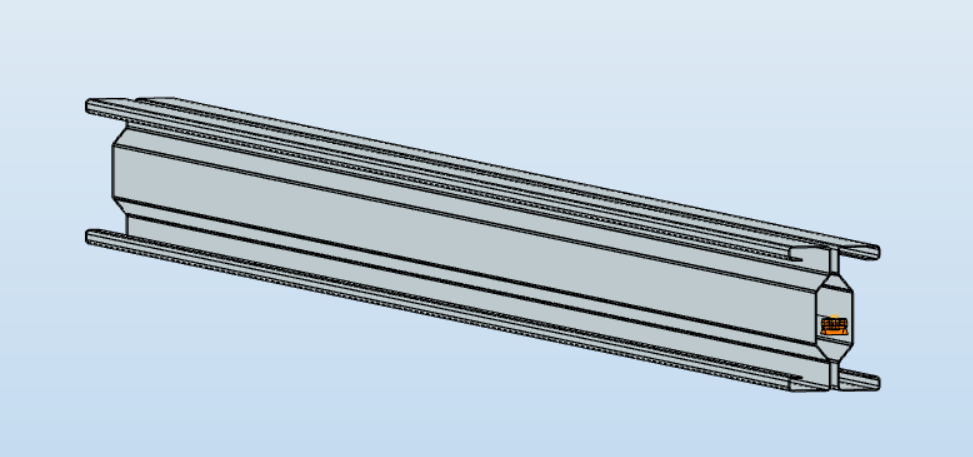
Cold-formed sections can be created using any of these four methods. Standard cold-formed cross-sections can simply be selected from the library. However, if a special cold-formed section is needed, it can be created via Macro Sections, including: RHS, CHS, L profile, Z shape, C shape, Sigma section, Zeta section, Hat section with stiffeners, double C section, double Sigma section, and double user-defined sections.
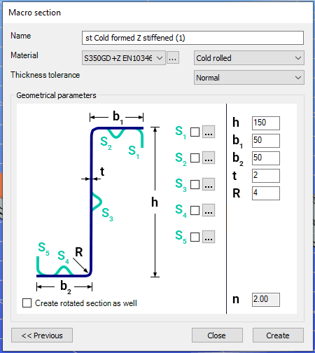
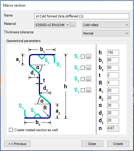
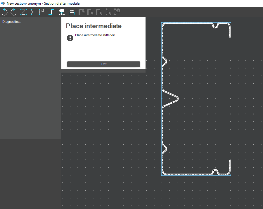
Macro sections are easy to create because the essential geometric characteristics are predefined, and the parameters can be modified intuitively. It is also possible to add profile stiffeners. Flange and web stiffeners can be configured in various forms, including single and double options. These defined stiffeners are included in the structural evaluation of distortional buckling, according to EN 1993-1-3.
The thickness tolerance category must be specified. This determines the design wall thickness for the section. In practice, macros follow the commonly applied tolerance categories used for coated steel sheet products.
If you want to use a double section, make sure to load into the model first the section that you want to duplicate.
For very special or unique sections, the Draw Section function can be used. This allows users to create fully custom cross-sections when standard or macro shapes are insufficient, by manually sketching the geometry.
Sections can be defined as cold-formed or general thin-walled, which determines how they are analyzed: cold-formed sections have uniform thickness and account for distortional buckling, while general thin-walled sections allow varied thicknesses and closed shapes, typically for welded or fabricated profiles.
This approach is especially useful for modelling unique shapes, prototypes, or as-built sections, giving full control over every segment to accurately capture geometries that standard libraries or macros cannot reproduce.
Download the example model and try it!
Download modelIf you haven’t tried Consteel yet, request a trial for free!
Try Consteel for freeDid you know that you could use Consteel to perform structural analysis at room and elevated temperatures as part of design process for fire resistance?
In structural fire engineering, the mechanical response of steel structures must be evaluated under both room and elevated temperature conditions. Consteel permits this by incorporating temperature-dependent material behavior directly into the finite element analysis, allowing engineers to assess not only resistance but also changes in global structural response.
During fire analysis, Consteel determines the steel temperature and applies the corresponding reduction in material properties, most notably the modulus of elasticity and yield strength. These reductions are defined according to Eurocode 3 (EN 1993-1-2). As a result, the calculated internal forces and deformations reflect both the applied loads and the effects of thermal expansion and stiffness degradation. The analysis is performed on the global structural model, so compatibility effects and force redistribution are inherently captured.
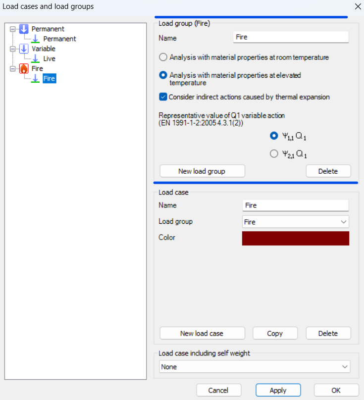
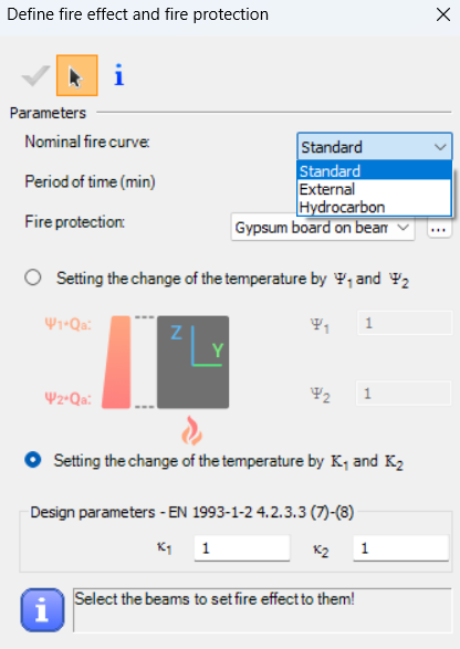
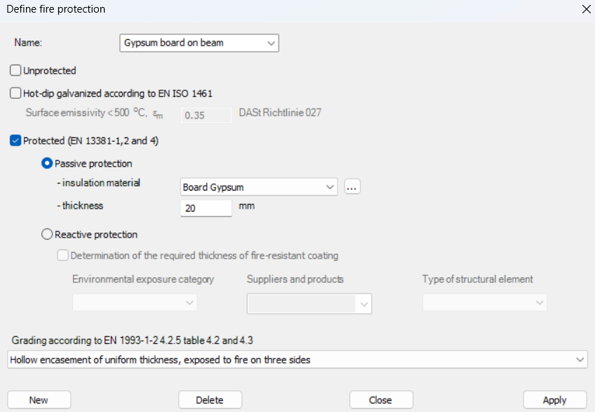
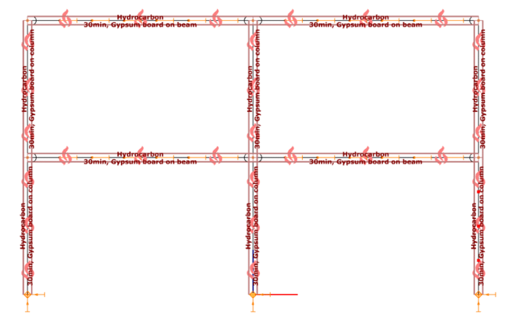
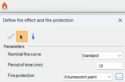
Fire exposure is defined using nominal fire curves (Standard, External, Hydrocarbon), together with a specified fire resistance time. In addition, the model allows assignment of fire protection conditions, including unprotected members, hot-dip galvanized surfaces, and protected elements with either passive insulation or reactive (intumescent) coatings. These definitions influence the temperature development in the structural members and, consequently, their mechanical response.
For design verification, Consteel applies the resistance models of EN 1993-1-2. Cross-section resistance is calculated using temperature reduction factors, depending on the type of internal force and cross-section class. Checks are performed for tension, compression, bending, and shear, as well as their interaction. For global stability, the software uses the Eurocode general method with modified buckling curves and reduction factors adapted for elevated temperatures.
In addition to elevated-temperature analysis, Consteel supports a complementary approach based on room-temperature analysis for critical temperature determination. In this case, the structural analysis is carried out with ambient material properties, and the objective is to find the temperature at which the reduced resistance equals the internal forces from the governing load combination. This method is particularly relevant for members with intumescent coatings, where the coating performance depends on the critical steel temperature. The calculated critical temperature can then be used to determine the required coating thickness based on product-specific data.
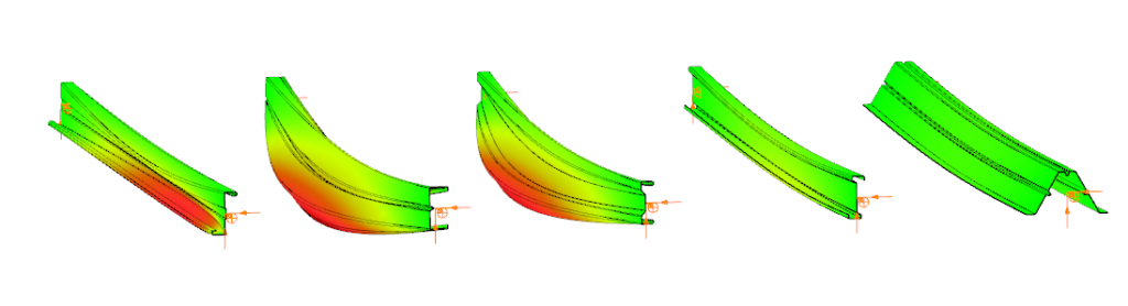
The difference between these two approaches can be illustrated using a two-storey frame model.
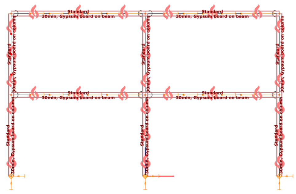
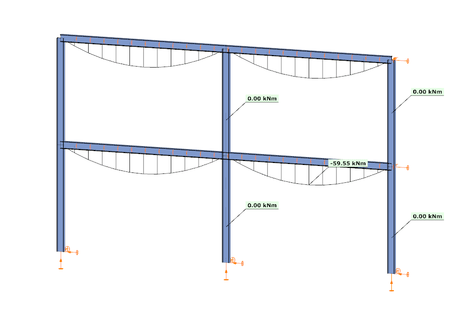
In the first case, the analysis is performed at room temperature. The beams develop a bending moment of approximately –59.55 kNm, while the columns carry primarily axial forces and show no significant bending moment along their length. This is consistent with the expected behavior based on the initial stiffness distribution of the structure.
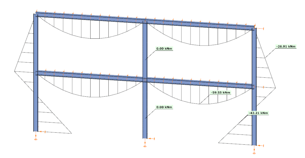
In the second case, the analysis is performed at elevated temperature, where reduced stiffness and thermal expansion are taken into account. The beam moment remains –59.99 kNm, but the internal force distribution in the structure changes. Bending moments appear in the columns, reaching approximately –26.91 kNm and –42.21 kNm at midspan.
This difference is a direct consequence of two coupled effects. First, the reduction in modulus of elasticity decreases the stiffness of heated members, modifying the relative stiffness distribution within the frame. Second, thermal expansion introduces additional deformations, which are partially restrained by the structural system. In statically indeterminate structures, such restraint generates additional internal forces, leading to redistribution of moments and the appearance of bending in members that were previously dominated by axial force.
From an engineering perspective, this comparison highlights that the internal force system under fire conditions is not a simple scaled version of the ambient-temperature state. Instead, it is the result of a different equilibrium condition, influenced by temperature-dependent material behavior and compatibility effects.
By allowing both types of analysis within the same model, Consteel provides a consistent framework to evaluate these phenomena. This supports more accurate assessment of structural performance in fire and enables informed decisions regarding fire protection and member design.
Download the example model and try it!
Download modelsIf you haven’t tried Consteel yet, request a trial for free!
Try Consteel for freeIntroduction
In ConSteel, there are three options for designing reinforced concrete columns: the Manual Nominal Curvature Method, the Automatic Nominal Curvature Method, and the Nominal Stiffness Method.
Each method has its advantages and disadvantages and should be used in different situations. We will now briefly review these methods and show how they can be used. Example models and a flowchart guide is also available at the end of the overview.
You can find the related chapters within the Online Manual about how to access these features in the Structural design and Structural modeling chapters.
Summary table
The following table summarizes the most important information about the three methods. Click on the table to see it in full screen.

We will now illustrate the application of these methods with a few short examples.
Examples
Manual Nominal Curvature Method
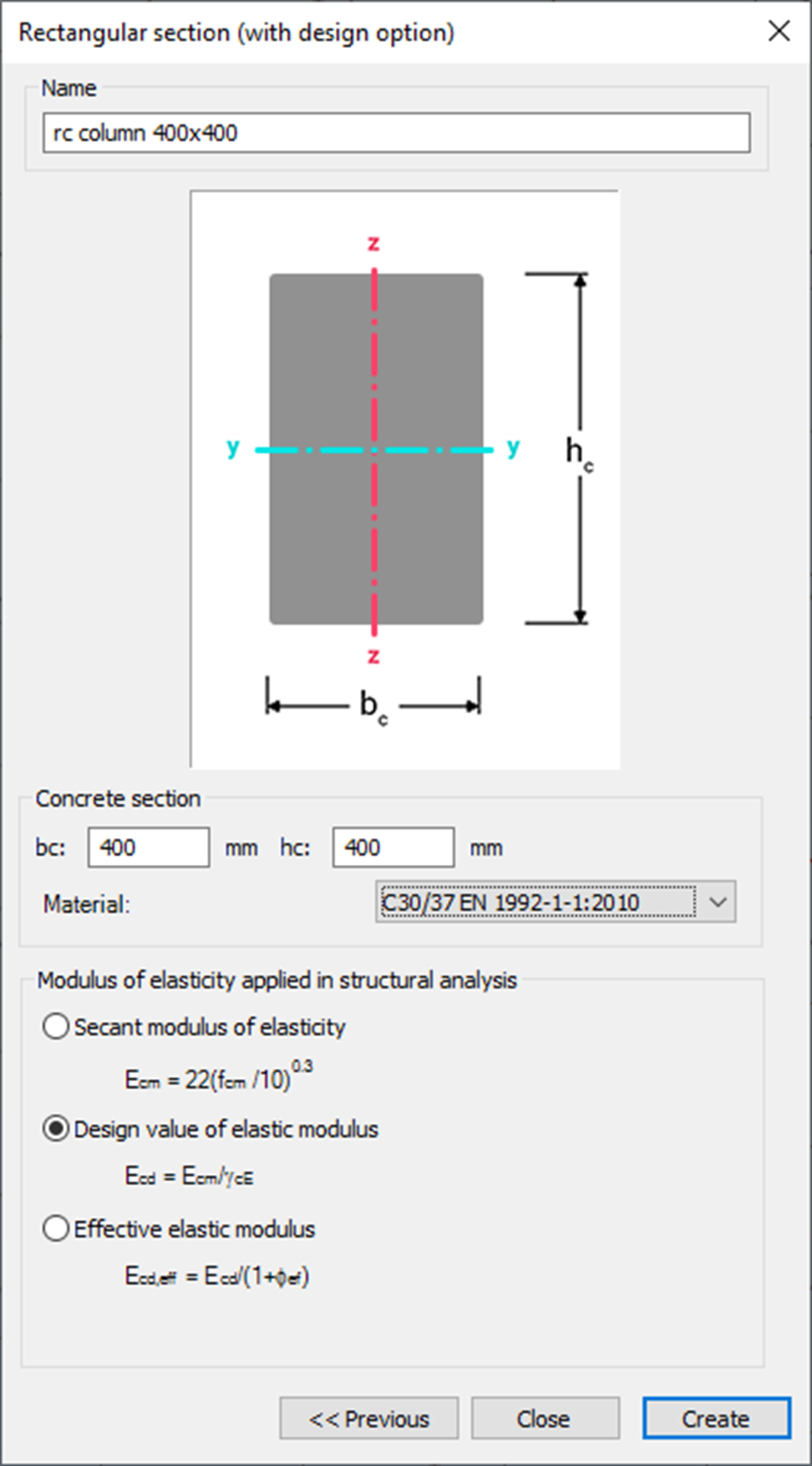
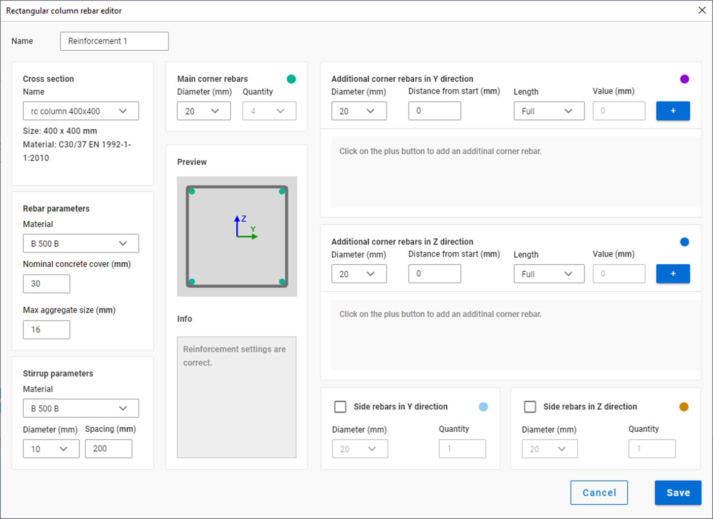
Create section
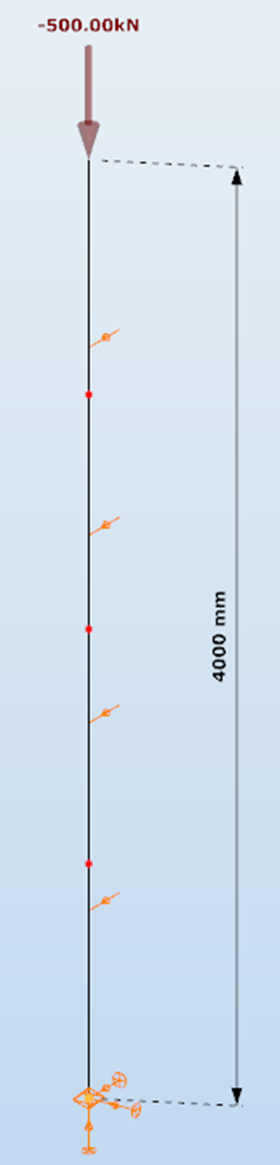
Define structure without imperfections
Define reinforcement
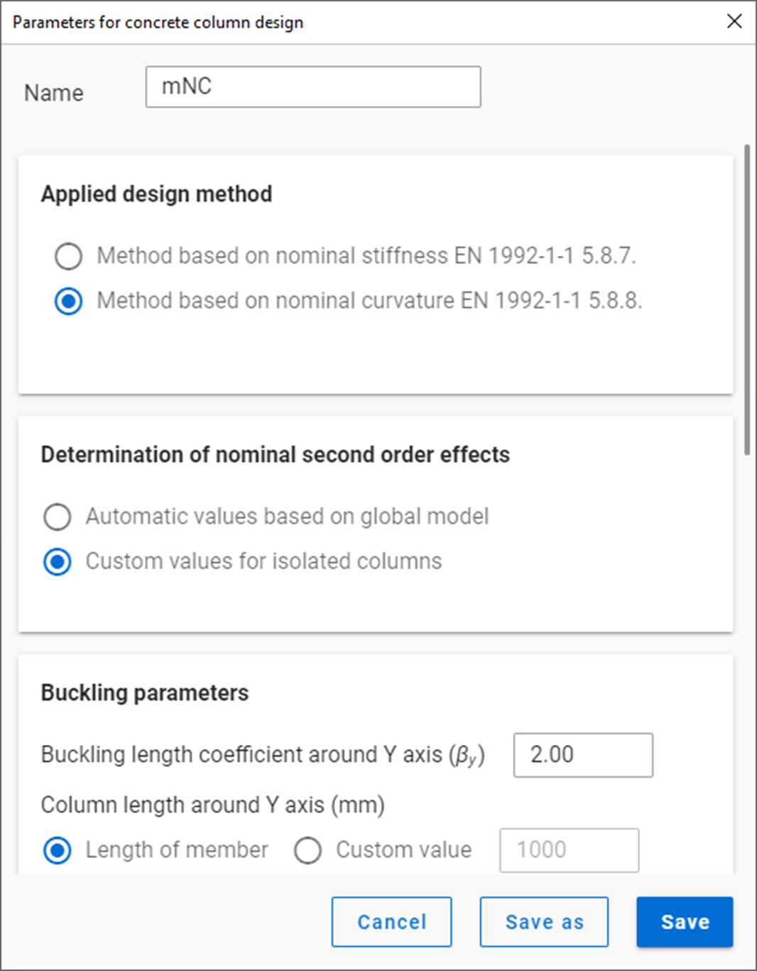
Define design parameters
First order analysis
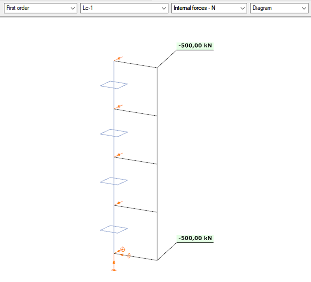
Design
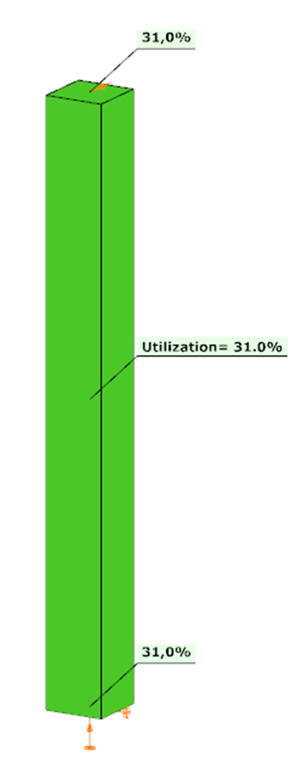
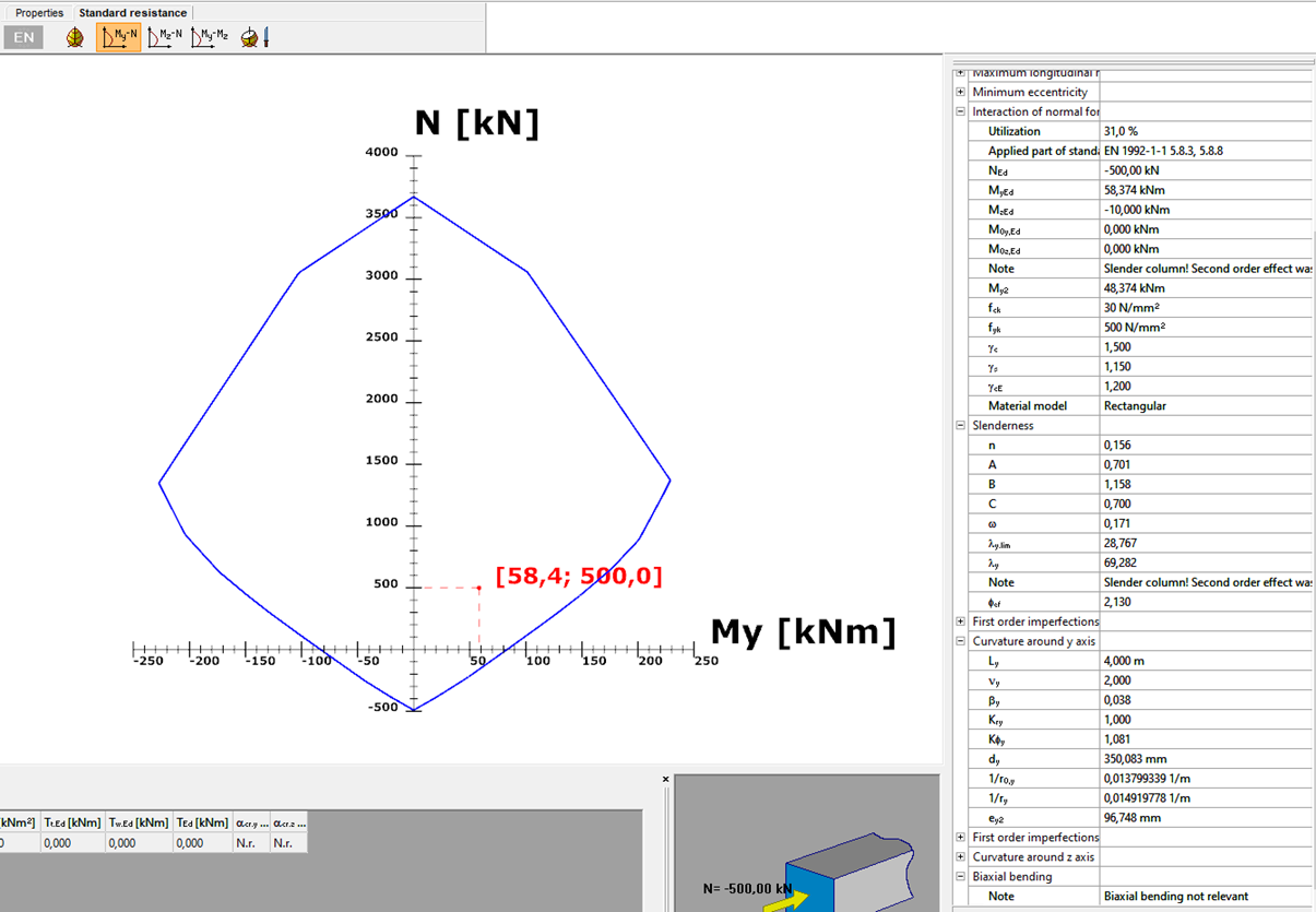
Automatic Nominal Curvature Method
Only the steps presented, which are different from the Manual Nominal Curvature Method.
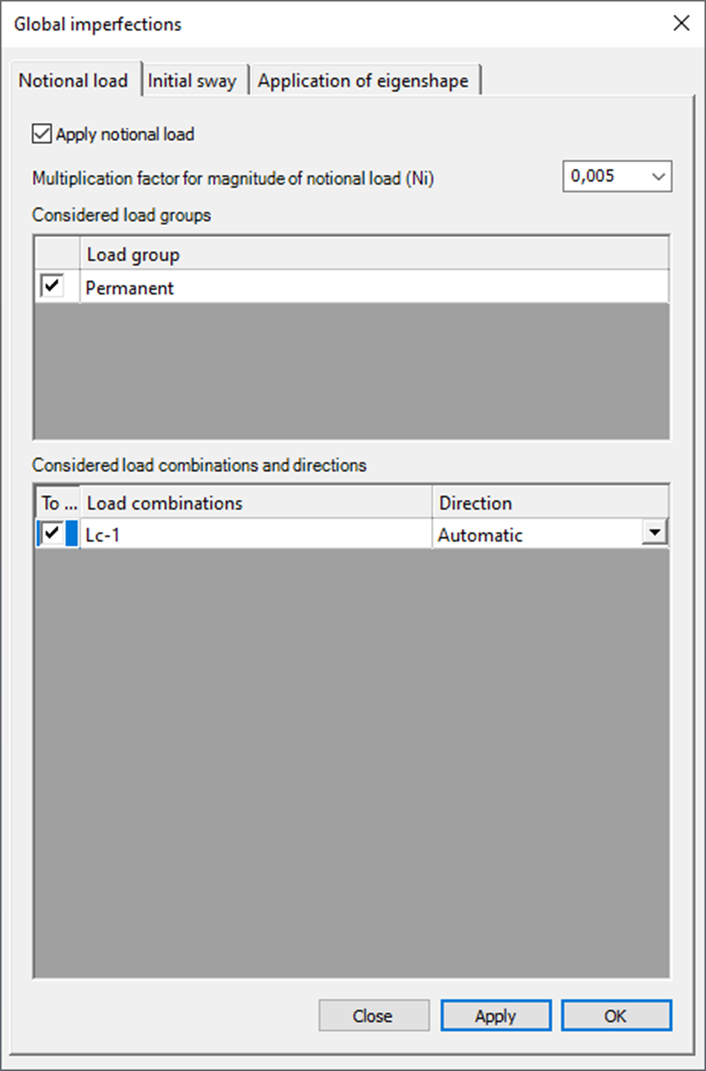
Imperfections
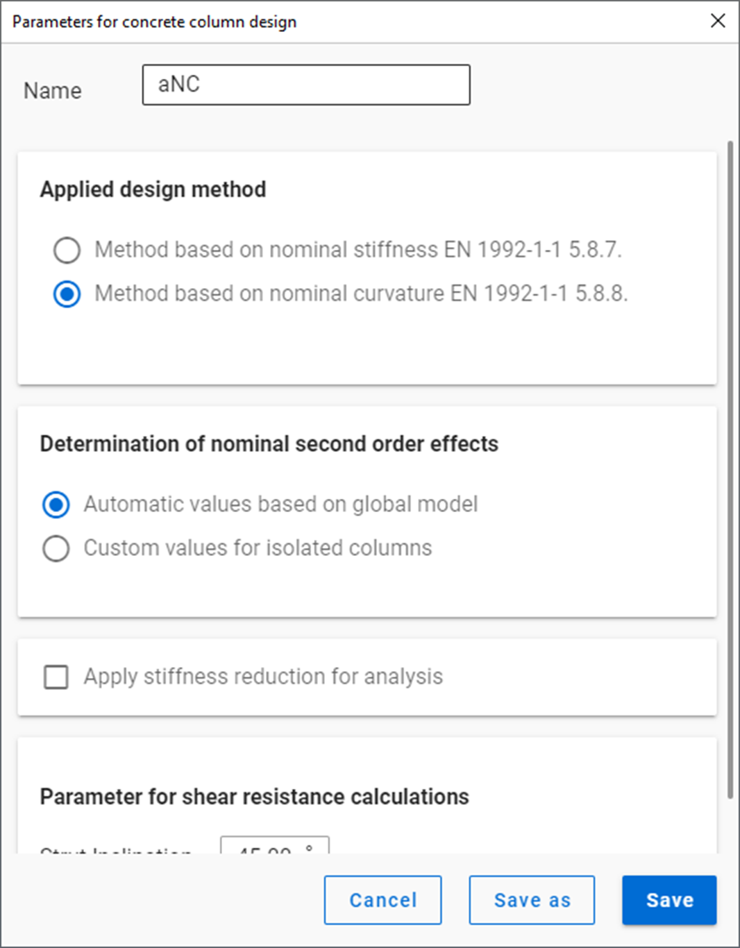
Design parameters
First order analysis – with imperfections
gateDid you know that you could use Consteel to design simple supported, continuous and over-lapped purlins systems, considering shear and rotational stiffness of attached roof sheeting?
Download the example model and try it!
Download modelIf you haven’t tried Consteel yet, request a trial for free!
Try Consteel for free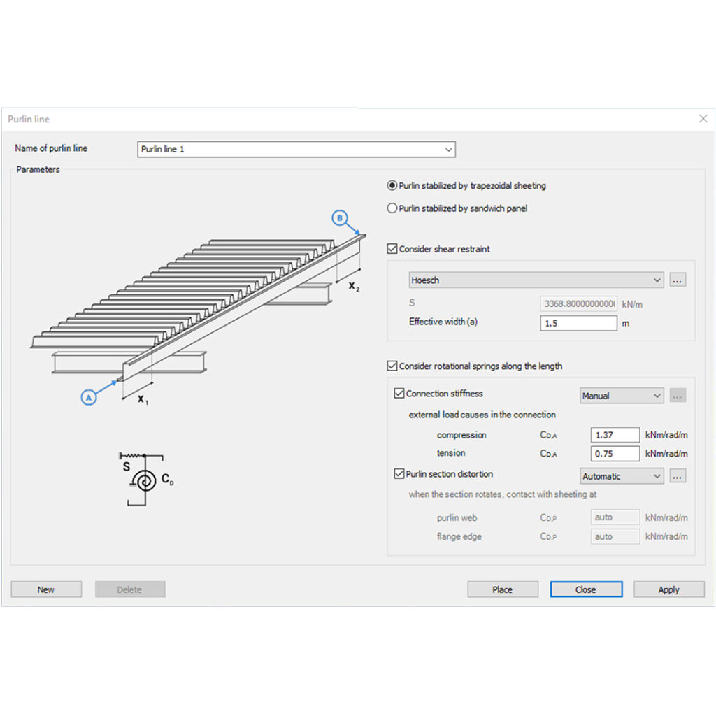
Did you know that you could use Consteel to determine the critical temperature of a steel beam protected against fire with intumescent painting?
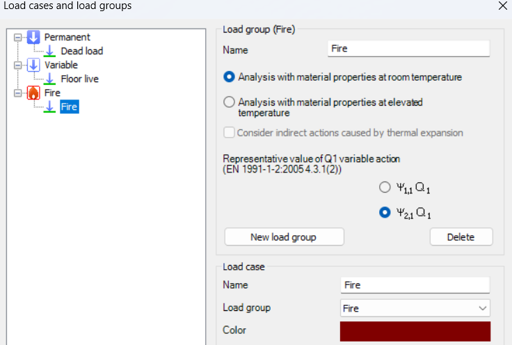
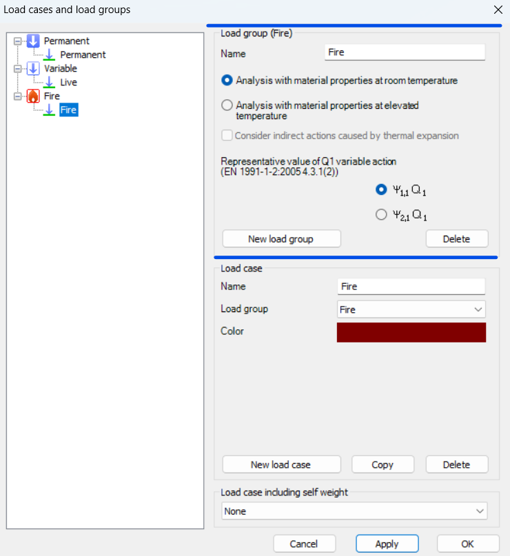
To perform this calculation, you first need to create a Fire load group and include at least one fire load case.
For critical temperature determination, the analysis must be set to room temperature material properties, because the objective is to find the exact temperature at which the steel section can no longer resist the applied loads while the intumescent coating reacts.
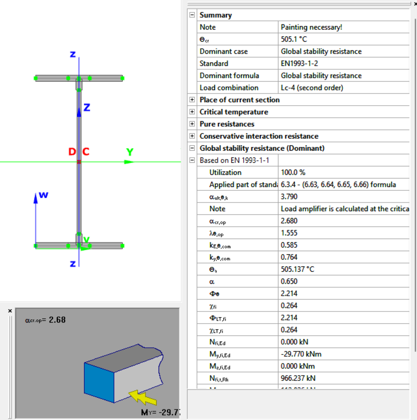
The key step is to assign reactive fire protection to the beam. This activates Consteel’s intumescent coating model, which calculates the temperature at which the reduced cross-section resistance equals the internal forces from the applied load combination. The software accounts for tension, compression, bending, and combined loading using Eurocode reduction factors, including interaction checks for complex load scenarios.
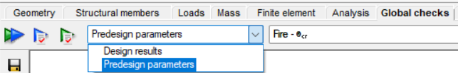
Results are available in the Predesign Parameters, where the critical temperature is visualized per member. You can also inspect detailed information in the Section Module, including the applied fire curve, the steel temperature profile, and the achieved versus required fire resistance.
Additionally, Consteel can optionally determine the required thickness of the intumescent coating from product tables based on the calculated critical temperature, considering the environmental exposure and structural element type.
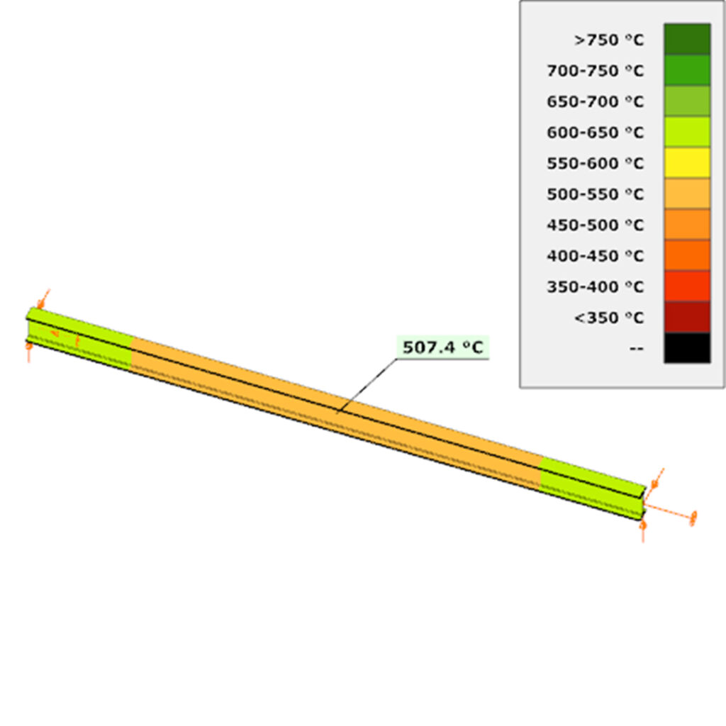
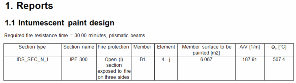
After completing the fire design, you can also include an intumescent paint design in the documentation. This report can list each cross-section selected for painting, along with the section name, fire protection surface to be painted, A/V ratio, and the critical temperature for each member.
Download the example model and try it!
Download modelIf you haven’t tried Consteel yet, request a trial for free!
Try Consteel for freeDid you know that you could use Consteel to design a hot-rolled crane beam considering the effect of code-prescribed load eccentricities?
Designing crane beams often involves more than simply applying vertical loads. Code-prescribed eccentricities, arising from rail positioning, wheel load distribution, and horizontal forces, can significantly influence internal forces and stability checks.
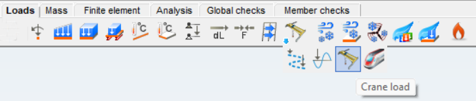
In Consteel, you can define three types of overhead traveling crane loads. The Standard option is fully based on EN 1991-3, following the code provisions directly. With Standard load based, you specify the standard-defined wheel loads, and Consteel automatically creates the corresponding load groups for you. The User defined option gives you full control, letting you input the wheel loads individually for each wheel, which is useful if your crane has a non-standard configuration.
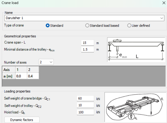
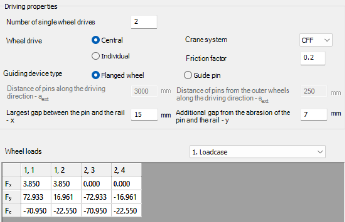
Once you select the type of crane load, you set the crane’s geometry, loading, and driving properties according to the chosen method. This includes parameters such as the crane span, trolley distances, number of axes, self-weight of the bridge and trolley, elevated load, number of driven wheels, drive system, friction factor, and guiding device.
For Standard and Standard load based options, Consteel calculates the wheel loads automatically and generates the load groups, while the User defined option lets you input each wheel load manually. The calculated wheel loads can be reviewed for each load case, helping you ensure that the crane beam design reflects the actual forces according to the selected standard or custom configuration.
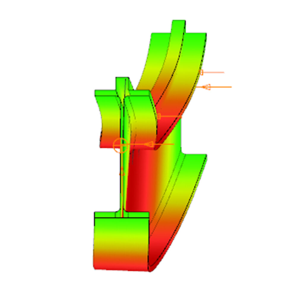
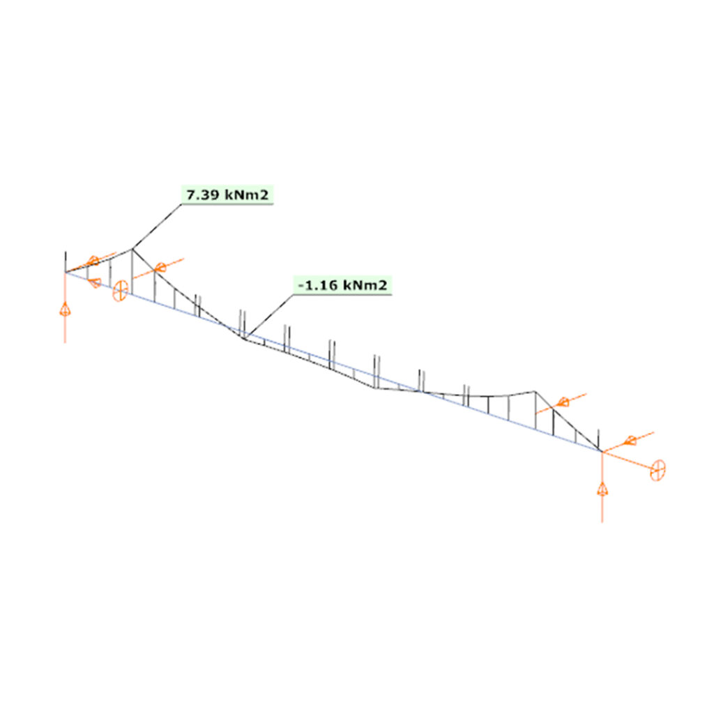
A key aspect of this method is that the eccentricity of the wheel loads is included directly in the analysis. This means that the internal forces along the beam account for the positioning and distribution of the loads.
By carefully defining the crane geometry, load magnitudes, and driving properties, the resulting bending moments and shear forces correspond closely to the real crane configuration, allowing for a reliable assessment of the hot-rolled crane beam under the prescribed loads.
Download the example model and try it!
Download modelIf you haven’t tried Consteel yet, request a trial for free!
Try Consteel for freeConsteel offers a range of load combination filtering options, which can be applied based on limit states, load cases, and analysis and design results. By applying different series of filters, designers can streamline their workflow and reduce calculation time.
Filtering options
Filtering is realized through the Load combination set definition window.
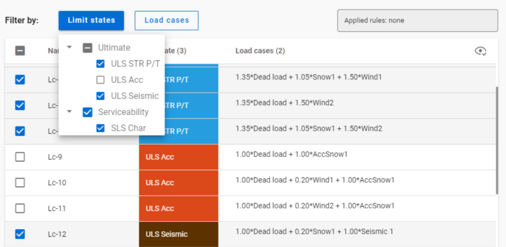
Filtering by limit states and by load cases are handled together with the checkboxes under the Limit states and Load cases buttons.
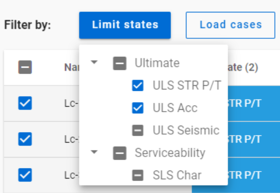
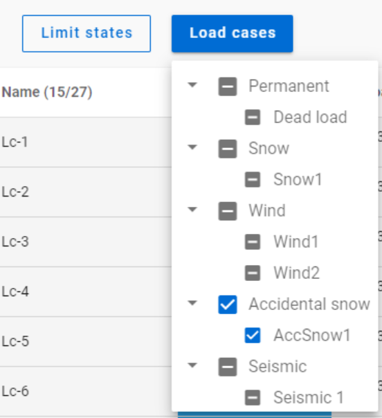
The 3-state checkboxes affect each other as they are not only used for selection but also for indication of the content. They can be manually set only to checked or unchecked. The middle state only appears when other filters are applied.
Filtering by limit states or load cases does not require any calculation results.
Filter by rules, on the other hand,is based on the actual analysis and/or design results. Different types of rules can be applied one by one or at the same time to select the desired load combinations.
When a rule is applied, all the load combinations that are selected on the Load combination set definition dialog- either with filtering by limit states/load cases or checked in manually- are examined at every position the rule indicates. Load combinations that meet the rule’s criteria are selected (remain checked in), while those that do not, become unchecked.
- With analysis rules, load combinations can be selected based on deformations or internal forces at either every finite element node or only at the member ends. This last one is included specifically for connection design. Deformations are checked in SLS combinations, internal forces are checked in ULS combinations only.
- With buckling rules, those ULS load combinations can be selected which have the elastic critical load factor (first buckling eigenvalue) less than the given limit.
- With design rules, load combinations can be selected based on utility ratios checked in every finite element node of the chosen portion. Utilizations are available from several design checks: dominant results and detailed verifications for steel elements such as general elastic cross-section check, pure resistances, interactions and global stability. Only ULS combinations can be filtered with design rules.
Interaction of the different filter types
Filtering by limit states, load cases, and rules can be used together, with rules being applied only to load combinations that are checked in and have the necessary calculation results.
Let’s see an example.
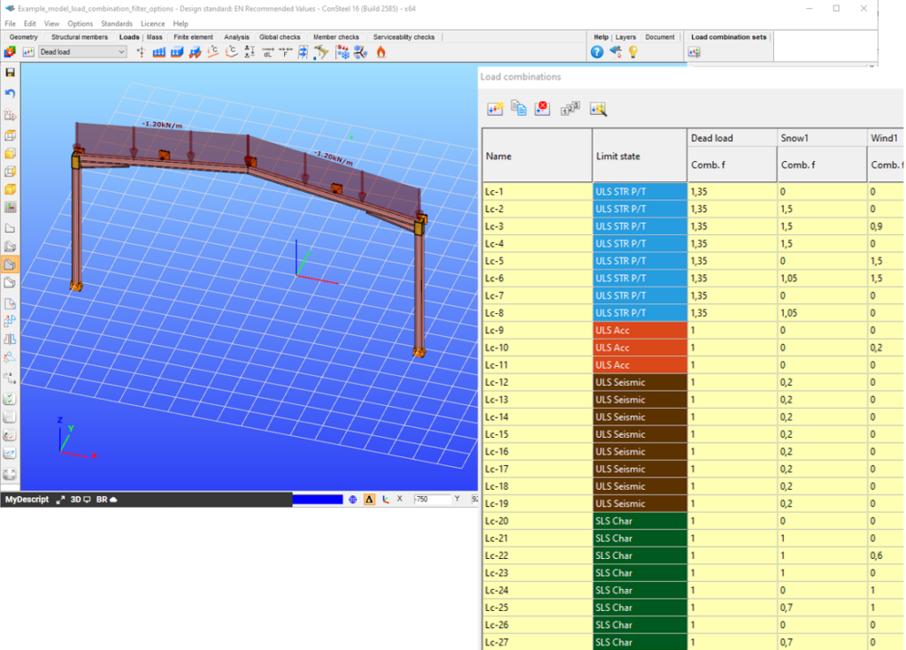
It is a simple 2D frame model, with 27 load combinations of various limit states generated. Analysis and design results are calculated for all load combinations.
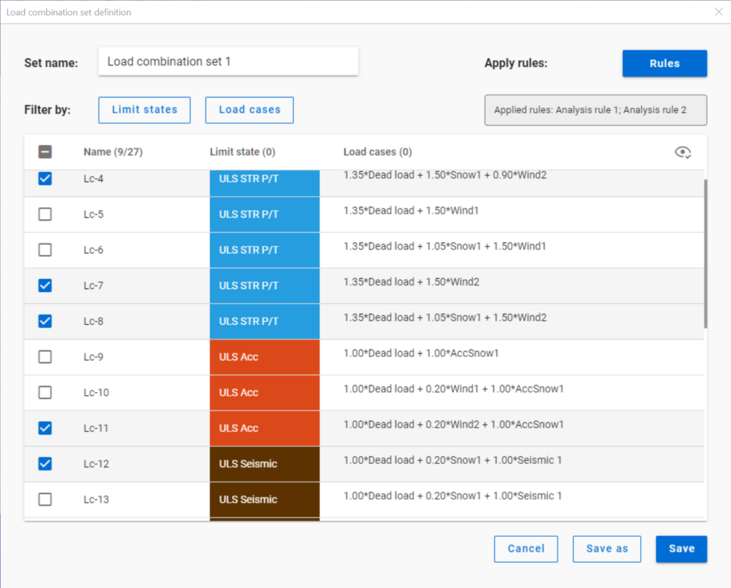
If applying design rule to select only those load combinations which result dominant utilization over 50%,
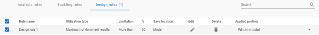
4 load combinations will be selected (Load combination set 1):
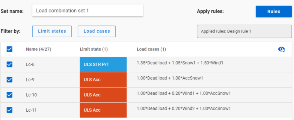
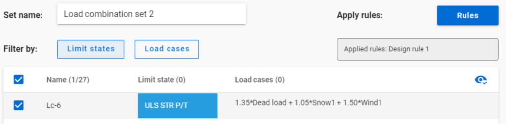
But if ULS Accidental limit state is turned off before applying the same 50% filter,
only one load combination is selected (see Load combination set 2).
Application of multiple rules
Applying multiple rules together results in the sum of the lists that would have been created separately.
gateThis paper discusses a combination of best practices and procedures from recent work in Europe and the US, providing rational and economical calculations addressing the complexities associated with frame design using nonprismatic members. Recommendations are provided in the context of US design practice. A primary objective is to achieve maximum simplicity, transparency, and design speed while facilitating rigor of the underlying calculations. The paper provides several focused examples illustrating the recommended design verification procedures.
Click the button below to download and read the full article.
GATEIn Consteel 16, we introduced the function of load combination filter. Filtering is possible based on the load combinations’ limit state, load cases, and corresponding analysis and design results. The goal is to create different sets for the different steps of the optimization and reduce calculation time while making sure that all the relevant load combinations are considered. Let’s see what a conscious design workflow looks like in practice!
Description
It is a significant problem in almost all structural design projects that the standards define many possible load cases and combinations to evaluate. Although most of these load combinations are never relevant or provide decisive design situations, it is usually not evident which ones might be neglected safely, especially when considering, that different load combinations can be relevant for different parts of the structure, like primary or secondary structure, connections, etc. Accordingly, the optimization process is overloaded by a large amount of unnecessary calculations.
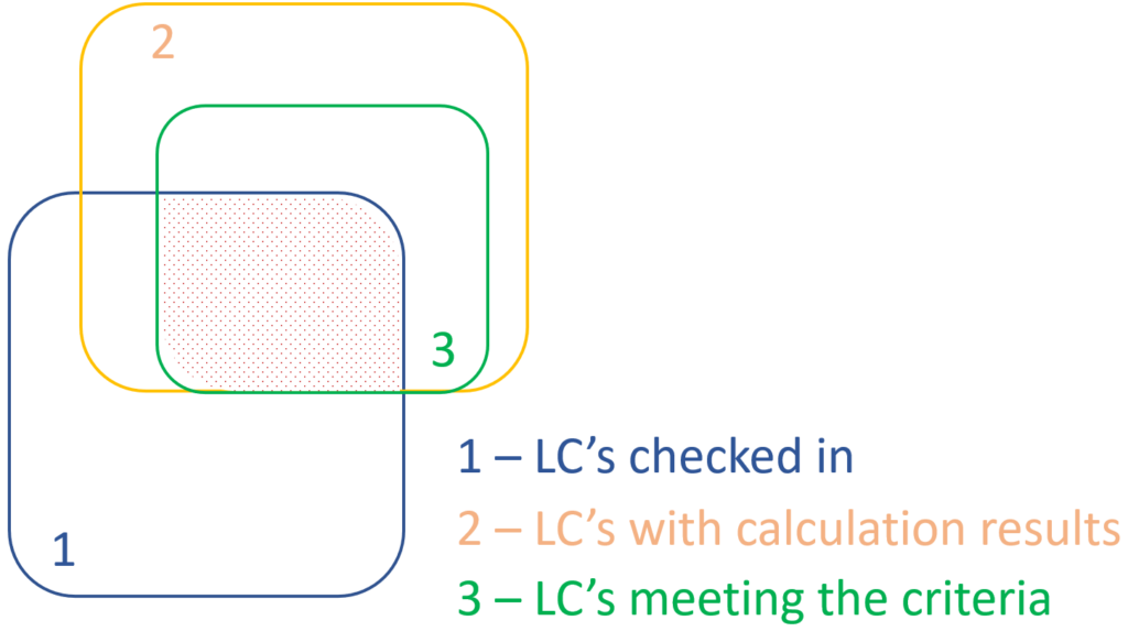
With the load combination filter function, a reduced list of load combinations aka a load combination set can be created and saved for the different steps of the optimization.
The optimal workflow for the filter may vary for the different purposes the sets are created for, but there is a recommended general process that can serve as the basis for all of them. First, run the simplest calculations and use the results for a rough selection which will already decrease the number of load combinations noticeably. Then one can increase the complexity of the calculations and further reduce the list of combinations by using stricter filters. If needed, this step can be repeated. This iterative process allows us to avoid complex and time-consuming calculations for all the thousands of load combinations.
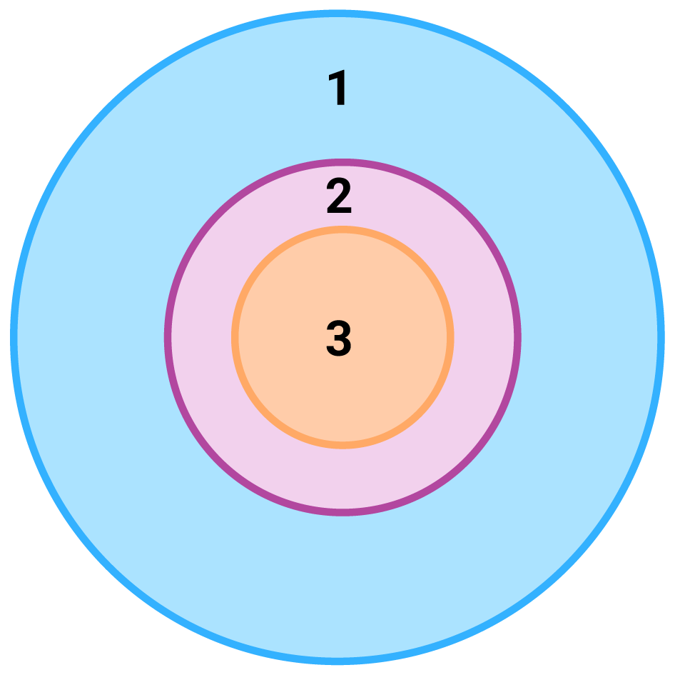
1 – all load combination, no filter;
2 – initial set with broad filter;
3 – working set with strict filter
Detailed process

Modeling
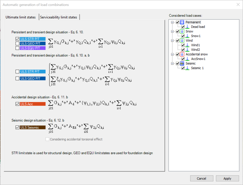
The base of all optimization processes is a correctly built structural model. So, the first step is geometrical and structural modeling and load definition. It is advisable to run a first-order analysis for only one or two load cases and diagnostics to find possible modeling errors. Load combinations can be created after that. Every limit state that will be used during the whole design of the structure, should be defined. Consteel’s automatic load combination generation function is an efficient tool to do it.
Calculation and filter
On the Load combination set definition dialog, it is possible to create load combination sets by selecting the combinations based on their limit state and/or the load cases they contain. But usually, filtering on specific analysis or design results will likely be more effective in reducing the number of combinations. Using the above-described general workflow, the steps are as follows:
gate