In Consteel 16, we introduced the function of load combination filter. Filtering is possible based on the load combinations’ limit state, load cases, and corresponding analysis and design results. The goal is to create different sets for the different steps of the optimization and reduce calculation time while making sure that all the relevant load combinations are considered. Let’s see what a conscious design workflow looks like in practice!
Description
It is a significant problem in almost all structural design projects that the standards define many possible load cases and combinations to evaluate. Although most of these load combinations are never relevant or provide decisive design situations, it is usually not evident which ones might be neglected safely, especially when considering, that different load combinations can be relevant for different parts of the structure, like primary or secondary structure, connections, etc. Accordingly, the optimization process is overloaded by a large amount of unnecessary calculations.
With the load combination filter function, a reduced list of load combinations aka a load combination set can be created and saved for the different steps of the optimization.
The optimal workflow for the filter may vary for the different purposes the sets are created for, but there is a recommended general process that can serve as the basis for all of them. First, run the simplest calculations and use the results for a rough selection which will already decrease the number of load combinations noticeably. Then one can increase the complexity of the calculations and further reduce the list of combinations by using stricter filters. If needed, this step can be repeated. This iterative process allows us to avoid complex and time-consuming calculations for all the thousands of load combinations.
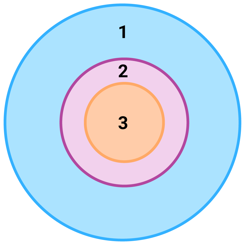
1 – all load combination, no filter;
2 – initial set with broad filter;
3 – working set with strict filter
Detailed process

Modeling
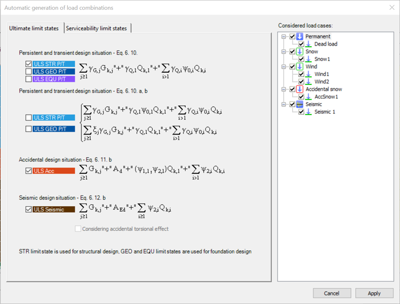
The base of all optimization processes is a correctly built structural model. So, the first step is geometrical and structural modeling and load definition. It is advisable to run a first-order analysis for only one or two load cases and diagnostics to find possible modeling errors. Load combinations can be created after that. Every limit state that will be used during the whole design of the structure, should be defined. Consteel’s automatic load combination generation function is an efficient tool to do it.
Calculation and filter
On the Load combination set definition dialog, it is possible to create load combination sets by selecting the combinations based on their limit state and/or the load cases they contain. But usually, filtering on specific analysis or design results will likely be more effective in reducing the number of combinations. Using the above-described general workflow, the steps are as follows:
gateDas neue Projekt Center vereint alle Funktionalitäten des Modell- und Benutzerkontenmanagements sowie den einfachen Zugriff auf personalisierte Informationen und Lernmaterialien.
Introduction
Are you wondering how a web opening would influence the lateral-torsional buckling resistance of your beam? Check it precisely with a Consteel Superbeam based analysis
It is often required to let services pass through the web of beams. In such cases the common solution is to provide the required number of opening in the webplate. Such an opening can have a circular or rectangular shape, depending on the amount, size and shape of pipes or ventilation or cable trays.
Beams must be designed to have the required against lateral-torsional buckling. The design procedure defined in Eurocode 3 is based on the evaluation of the critical bending moment value which provides the slenderness value, needed to calculate the reduction factor used for the design verification.
There is no analytical formula provided in the code for beams with web openings. Would the neglection of such cutouts cause a miscalculated and unsafe estimation of the critical moment value?
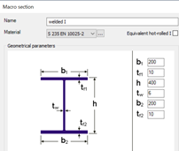
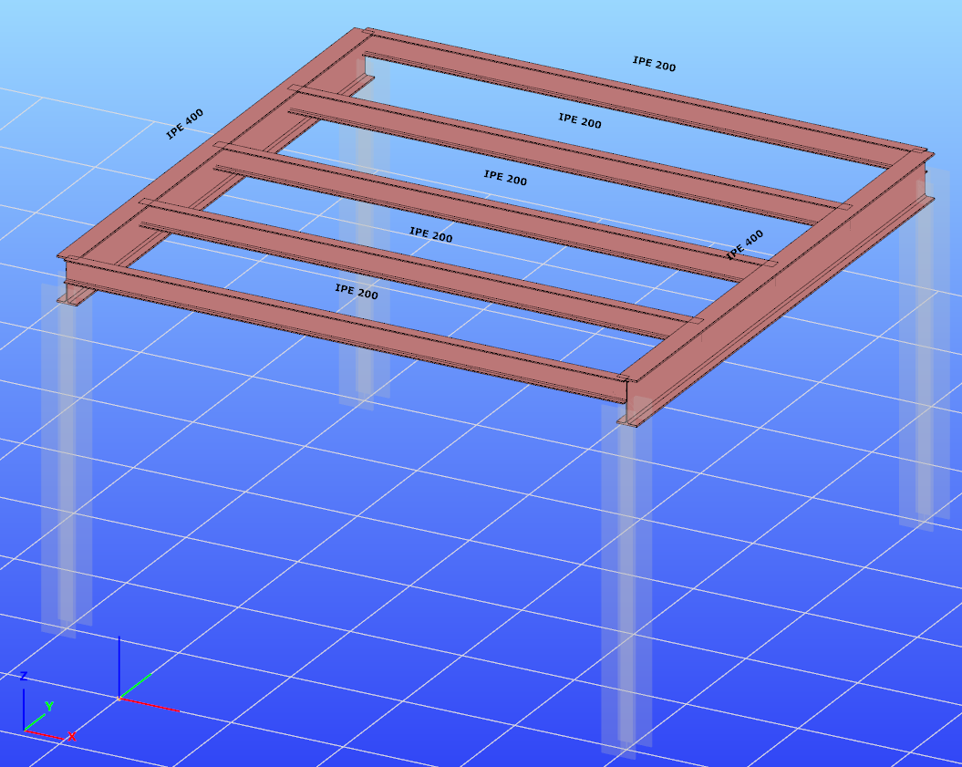
The following demonstration will be made with a 6 meters long simple supported floor beam with a welded section.
Exposed to a linear load of 10 kN/m, the critical bending moment value of the solid web beam can be obtained by performing a Linear Buckling Analysis (LBA) with Consteel.
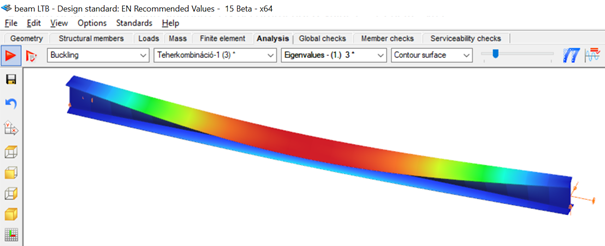
The obtained critical multiplier for the first buckling mode is 3.00 which means that the actually applied load intensity can be multiplied by 3.00 to reach the critical load level. The corresponding critical moment will have the value of Mcr = 3.0 * 47.18 = 141.54 kNm yielding a slenderness of 1.286 (Mpl,Rd = 234.20 kNm) and a lateral-torsional buckling resistance of 0.394 * 234.20 = 92.27 kNm. With this value the actual utilization ratio is at 51%.
How would this value change if a rectangular opening needs to be cut into the web of this beam?
Analytical formula for critical bending moment
By looking to the analytical formula (ENV 1993-1-1 F.4) to calculate the critical moment of double symmetric sections loaded at eccentric load application point it becomes obvious that the section properties having effect on the moment value are Iz, Iw and It.
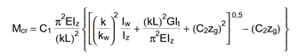
An opening in the web has no effect on the first two values and has very little effect on the last one. As it has been already shown in previous article, the presence of such an opening can have effect on the vertical deflection, but as long as the lateral stiffness of a beam is much lower than it’s strong axis stiffness, the vertical deflections can be neglected when the lateral-torsional buckling resistance is calculated. The usual linear buckling analysis (LBA) performed also by Consteel neglects the pre-buckling deformations.
Therefore one can expect that in general web openings can be disregarded when the critical moment value is calculated.
Analysis with Consteel Superbeam
Beam finite elements cannot natively consider the presence of web openings. In order to obtain the precise analysis result, it is possible to use shell finite elements. The new Superbeam functionality comes as a solution in such cases. Instead of using beam finite elements, let’s use shell elements!
Opening can be positioned easily along the web, either as an individual opening or as a group of openings placed equidistantly. The opening can be rectangular, circular or even hexagonal. Circular openings can be completed with an additional circular ring stiffener.
The rectangular opening for this example can be easily defined with this tool. As there is no need to provide any additional opening on the remaining part of the beam, only the first part which includes the opening will be modelled with shell elements and the rest can still be modelled with beam finite elements. Using this technique, the total degrees of freedom of the model can be kept as low as possible. When using Superbeam, the designer has the choice whether to use beam or shell finite elements, as appropriate.
gateExample hall model for trying the smart link feautre in Consteel

Watch our user guide about How to use the smart link feature to learn more.
gateExample model for trying the smart link feature in Consteel
Watch our user guide about How to use the smart link feature to learn more.
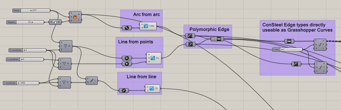
gateGeometry definition
Geometry in Pangolin can be described by lines or circular arcs and polygons made up of the former two. The relevant components are the simplest ones, acting as converters from the native Grasshopper geometry types, with the possibility of specifying a Consteel Layer.
Section definition
The geometry definition of the sections is more refined since Consteel uses detailed section models composed of solid representation for analysis and thin-walled representation for standard design checks. There are two options to create sections in Pangolin: use a predefined section from the section bank or create custom sections by predefined parametric macros.
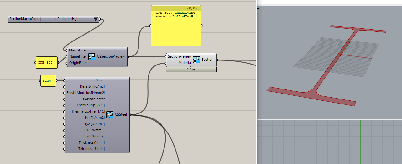
Predefined sections from section bank
7000+ different profiles can be defined from the section bank (hot-rolled, cold-fromedetc.). This workflow contains two steps: 1. Getting the section preview from the bank. 2. Getting the actual section from the preview. (The reason for this is the performance, as in Pangolin sections are real objects, loading all the 7000+ sections from our bank would take minutes even on a powerful pc.) The section bank component provides various filtering options, to help select the section. After the desired section preview is selected, you can create a real section from it along with a material, and check the cross-section surface in Rhino.
Custom sections based on predefined macros
This workflow consists of placing a section macro component, selecting a base macro, and defining the macro parameters.
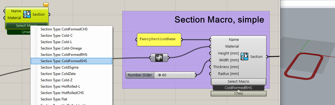
One of the most important unique features of Consteel is its advanced analysis and design calculations for members with cold-formed sections having various stiffeners. Correspondingly Pangolin makes it possible to create custom cold-formed sections, with custom stiffeners parametrically:
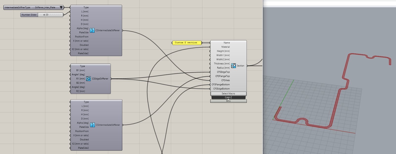
As you can see, the components help in building complex sections with available default values providing a wide range of parameters to be customized.
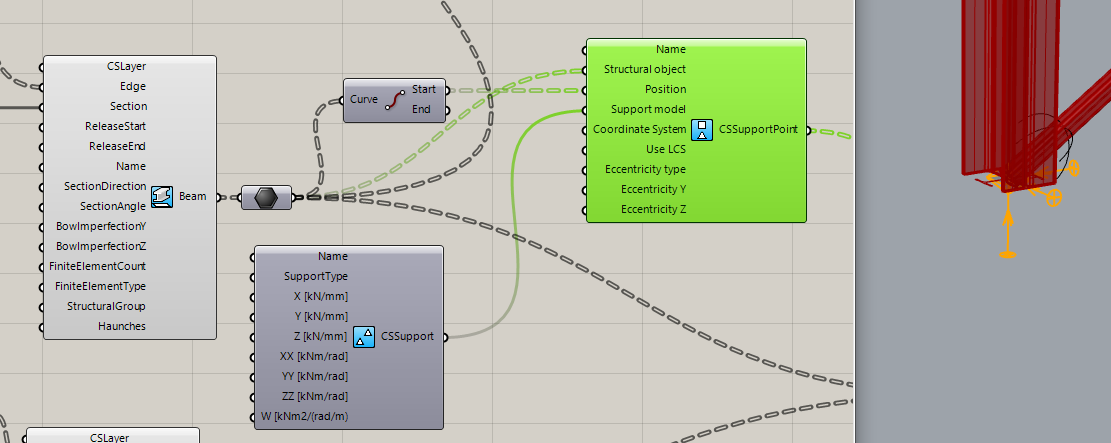
Structural member definition
Defining beams is as easy as pulling the reference edges and the beam section into the Beam component:
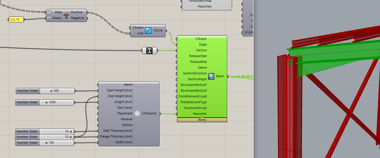
In the example above we also defined a haunch on the beam ends, another unique feature of Consteel, which will be taken accurately into account during analysis and design.
To make modelling easier, Pangolin also provides several useful implicit data conversions, like in the picture above: at the start, we have the IPE 300 beams, and just connecting them into a Grasshopper Plane parameter, the beams get converted to their local coordinate systems. This plane can be directly connected with the Z purlins section direction parameter to correctly lay them upon the main beams.
Structural details
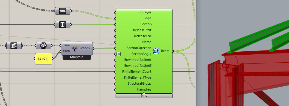
Let us stop at the purlins for a moment! Pangolin also provides a detailed linking of structural objects through Consteel’s link elements which can be rather important in order to consider accurately the lateral restraint effect on the beam provided by the purlins.

The definition of link elements includes setting the interface position, the direction, and the stiffness attributes of the connection. Defining supports for the model is also helped by automatic conversions, where you can directly ask a beam’s endpoint, and place the support there, instead of manipulating with indexes through a complex definition.
Pangolin also provides the possibility to define edge and plate supports.
Load definition
gateConsteel is a powerful analysis and design software for structural engineers. Watch our video how to get started with Consteel.
Contents
- Define load groups and load cases
- Generate load combinations
- Define line loads globally
- Define partial line loads locally
Consteel is a powerful analysis and design software for structural engineers. Watch our video how to get started with Consteel.
Contents
- Load sections
- Creating beams and columns
- Place supports
- Haunch definition
- Frame corner definition
Read our tips and tricks about Surface wind load on custom shape roof for more information.
Version: CS14.1000
gate
Read our tips and tricks about Placing of multiple point supports for more information.
Version: CS14.1000
Click the button below to download the example model.
gate