Did you know you can use Consteel to run second-order and buckling analyses on specific parts or elements of your model by defining a Custom Portion for the portion of interest?
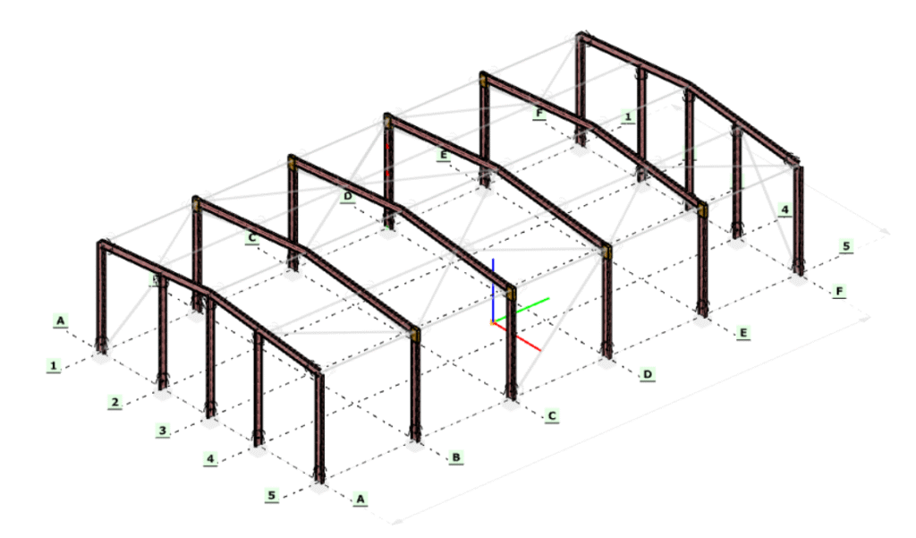
The workflow starts in the Portions Manager, where you can manually group structural members, frames, columns, beams, bracings into Custom Portions. These are fully user-defined and, importantly, only these custom portions can be directly used for analysis. This allows you to isolate exactly the structural subsystem you want to investigate, without being constrained by the full model.
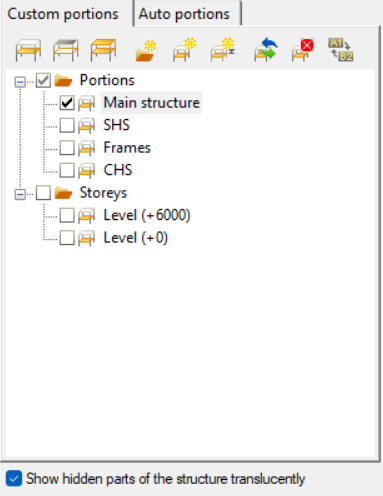
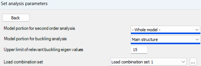
Once a portion is defined, it can be selected in the Analysis Settings, where you can choose whether second-order and buckling analyses should be performed on the entire model or only on the selected portion. The solver will then consider only that subset of elements when assembling the stiffness matrix and evaluating stability behavior.
Running these analyses on specific portions has clear engineering advantages. Second-order effects and buckling phenomena are often governed by local structural behavior, such as a critical frame, a bracing system, or a column group, rather than the entire structure. By isolating these regions, you can:
- reduce computational effort and analysis time, especially for large models
- focus on the most critical load paths and instability mechanisms
- perform faster iterations during design refinement
- avoid unnecessary influence from non-relevant parts of the structure
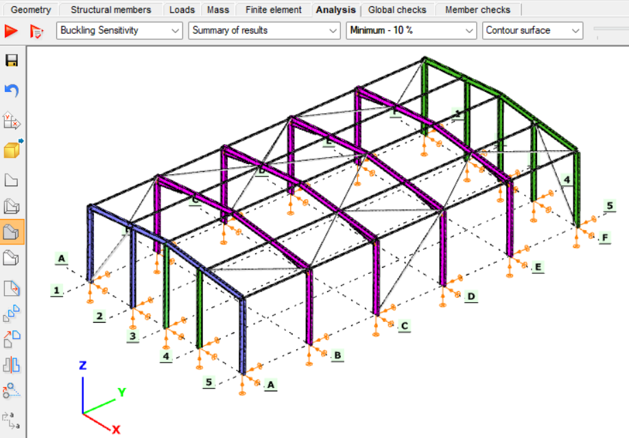
This targeted approach leads to more efficient and controlled stability analysis, particularly when investigating sensitive or highly utilized structural components.
Download the example model and try it!
Download modelIf you haven’t tried Consteel yet, request a trial for free!
Try Consteel for freeIn this article, we aim to answer the question: Why are there two different procedures for exporting connections to IDEA StatiCa? Let’s explore the difference between using the Connection interface and Checkbot export.
IDEA StatiCa Connection
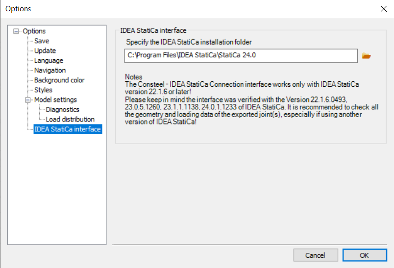
In order to use the IDEA StatiCa Connection link, please make sure that the program is installed and that the folder location is specified in the IDEA StatiCa Interface ‘Options menu‘.
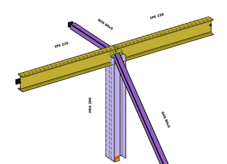
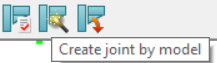
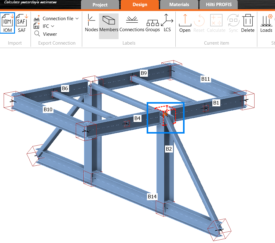
The conversion starts on the Structural Members tab, using the ‘Create Joint by Model‘ function. After selecting the appropriate intersection between members, a new window will appear.
If the ‘IDEA StatiCa Connection’ type is selected, the IDEA StatiCa application will launch automatically, and the selected connection will be transferred.
Using this method and placing the joints into the Consteel model (possible in multiple positions with similar geometry), a direct connection is established between the two programs. This means that geometry (cross sections, materials) and internal forces (according to all combinations of locations where the joint is placed) are taken directly from Consteel.
IDEA StatiCa Checkbot
The IDEA StatiCa Checkbot export can be accessed from the ‘File menu’ by selecting it from the ‘Exports section’. Users must define a location where the entire model will be exported in .xml format. This file can later be imported into IDEA StatiCa Checkbot using the IOM (IDEA Open Model) import option.
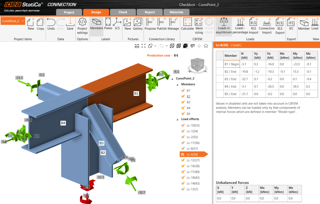
The full 3D model is imported using this method, and all joints can be analyzed individually within the IDEA StatiCa. A list of all imported items will appear in IDEA, each marked with a status such as ‘Checked’ or ‘Not Checked’. The imported members can be visualized in 3D, along with the applied loads.
The conversion supports materials, cross-sections, and load combination management. The internal forces resulting from the Consteel analysis for ULS combinations are available in IDEA StatiCa. This approach also ensures that the internal coordinate systems for all internal forces are preserved accurately.
All connections present in the imported model can be exported to IDEA StatiCa Connection, where joint design is carried out. You can choose to export a single connection or select multiple connections and save them in one file, allowing you to design the connection or print reports for all modeled connections at once.
Connections designed in Checkbot can only be considered in the global analysis phase in Consteel if the calculated stiffness is manually introduced at the release ends.
When to choose the direct link to IDEA StatiCa Connection?
Use direct link IDEA StatiCa Connection when you want to jump directly to the connection design in IDEA. Since the joint can be placed in multiple locations within the Consteel model, all internal forces from all combinations and all positions where the joint is placed will be taken into account.
A key advantage is that if you’re still working on your 3D model and changes occur, there’s no need to regenerate the link, simply update and verify the changes directly in IDEA StatiCa.
When to use IDEA StatiCa Checkbot Export?
Use Checkbot export when your structure contains many irregular or complex joints.For instance, if the bars in the connections do not intersect at a single point due to eccentricities or lack of space, you can merge them into one connection using Checkbot.

Conclusion
In summary, from the perspective of model updates and quicker access, using the direct connection via IDEA StatiCa Connection is generally the better choice, especially if the integrated Consteel Joint doesn’t provide enough flexibility for joint creation.
IDEA StatiCa Checkbot export offers significant advantages in terms of automated member recognition, possibility to merge joints, accurate assignment of internal forces, and efficient bulk joint analysis. It eliminates the need to manually verify force directions or coordinate systems, streamlining the workflow, especially for larger or more complex structures.
The main limitation of Checkbot export is that it establishes a one-way connection: every time the Consteel model changes, a new export is required in order to stay updated with the changes. Therefore, the choice between methods should depend on the nature of your project, if the model is expected to change frequently, the direct connection is more suitable. However, if you’re working with the final geometry and need to verify complex joints, the Checkbot export is the better option.
Did you know that Consteel provides a plugin to integrate structural modeling and analysis into your parametric Grasshopper definitions?
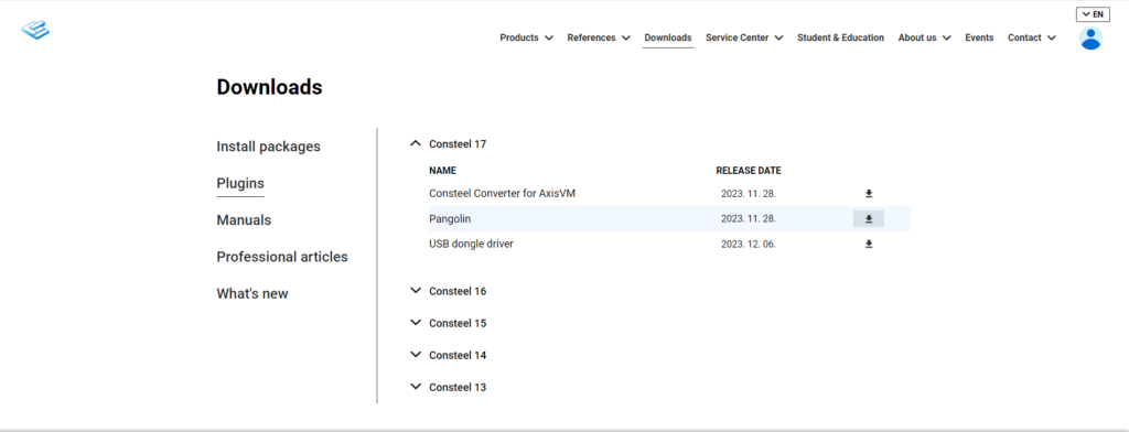
Download Pangolin from food4rhino.com or the Yak package manager of Rhino. You can also download it by logging in to our website. See Downloads/Plugins menu:
How will you possibly work in Pangolin? See the related videos on our YouTube channel, starting with the ‘Introducing Pangolin‘ video.
If you haven’t tried Consteel yet, request a trial for free!
Try Consteel for free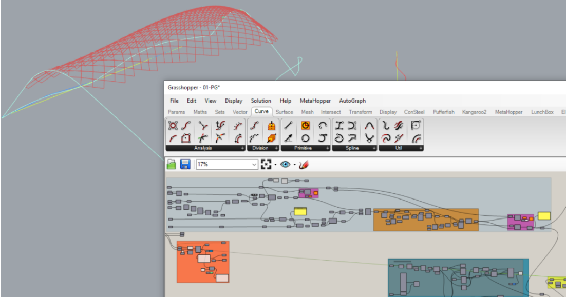
Did you know that you could use Consteel to calculate rotational stiffness for bolted column/beam moment bearing connections?
This capability is implemented through the Joint module, where connection behavior is evaluated in accordance with Eurocode EN 1993-1-8. The software does not treat joints as idealized (purely pinned or rigid), but allows the engineer to consider semi-rigid behavior by calculating the actual rotational stiffness based on connection components such as bolts, end plates, welds, and stiffeners.
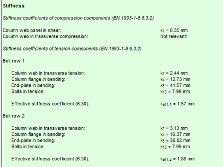
In practical terms, the rotational stiffness is derived from the component method, where the stiffness contribution of each tension and compression component is taken into account. This enables a more realistic representation of the joint response, especially for moment-resisting beam-to-column connections where stiffness significantly influences global structural behavior.
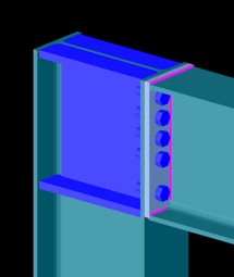
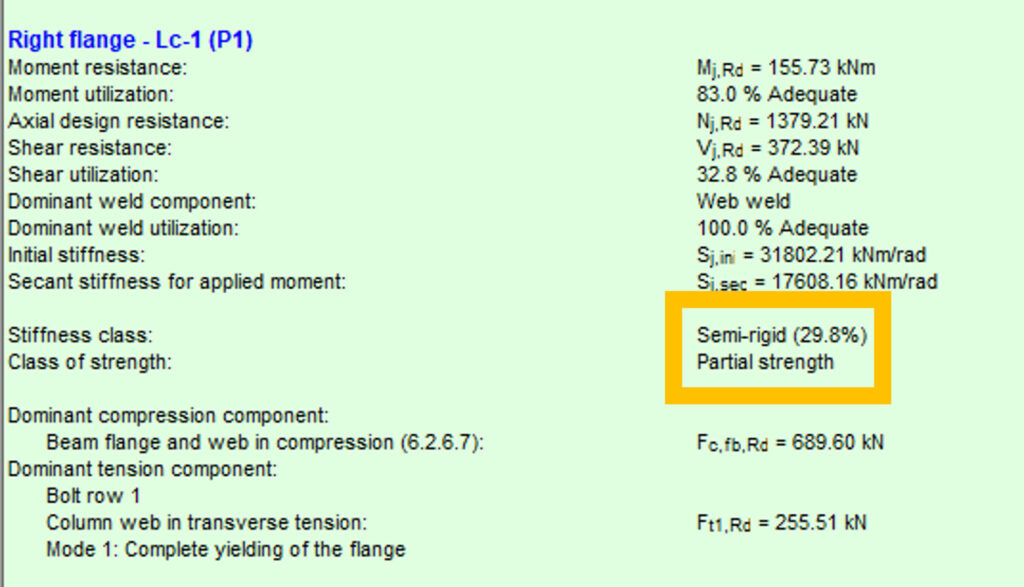
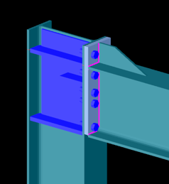
Bolted connection
In this case, the connection exhibits relatively low rotational stiffness compared to a fully rigid joint. The flexibility is primarily governed by bolt deformation and end plate bending. Such connections are typically classified as semi-rigid and partial strength. They allow noticeable rotation under moment, which can be beneficial for redistribution of internal forces but must be considered in global analysis.
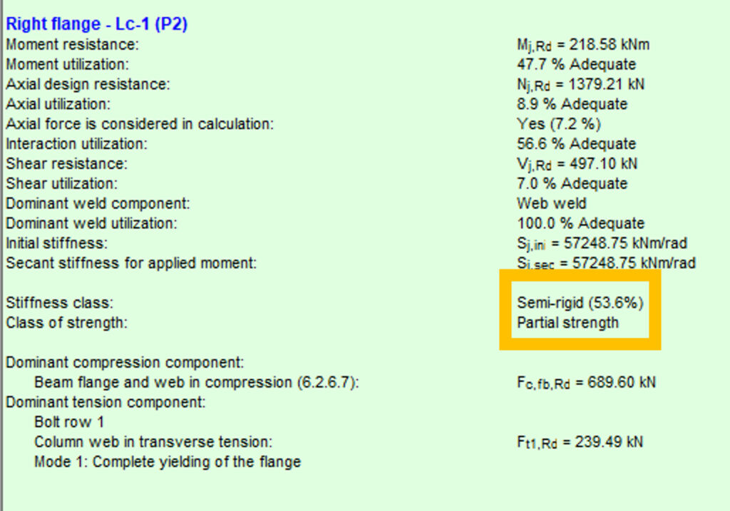
Bolted connection
This configuration shows a higher stiffness due to improved component arrangement, such as thicker end plates, larger bolt diameters, or additional stiffening. Although still semi-rigid, the connection provides significantly more resistance to rotation. This intermediate behavior often results in a more efficient structural system by balancing stiffness and material usage.
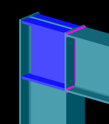
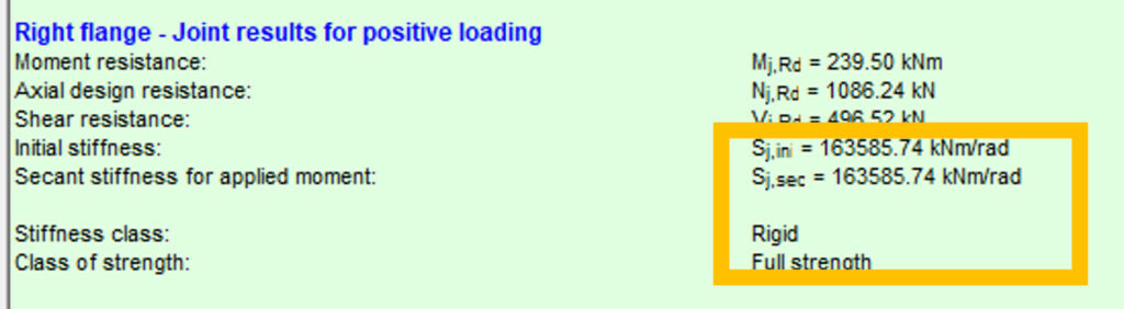
Welded connection
The welded joint behaves as a rigid connection with full strength. Rotational stiffness is high enough that joint deformation has negligible influence on the global structural response. In Consteel, this is reflected by a stiffness value approaching the rigid classification limit defined by the standard. Such connections are typically used where continuity and moment transfer must be ensured without significant rotation.
Using the Joint module, these behaviors can be modeled and evaluated through a structured workflow:
- Joint creation: Define the connection either manually or based on the global structural model using automatic recognition.
- Connection configuration: Assign geometry, cross-sections, bolt layouts, welds, and optional stiffeners.
- Loading definition: Apply either user-defined internal forces or import them directly from the global analysis.
- Analysis: The software evaluates moment resistance, shear resistance, and both initial and secant rotational stiffness using Eurocode-based procedures.
- Integration: The calculated stiffness can be applied back to the global model, enabling second-order effects and realistic force distribution.
Considering rotational stiffness leads to more accurate structural models. Instead of assuming ideal boundary conditions, the engineer can:
- Reduce conservatism in member design
- Capture redistribution effects in frames
- Optimize connection detailing
- Improve overall structural efficiency
This approach is particularly important in steel frames where joint flexibility can significantly affect deflections, internal forces, and stability.
Download the example model and try it!
Download modelIf you haven’t tried Consteel yet, request a trial for free!
Try Consteel for freeDid you know that you could use Consteel to perform dual analysis with 7DOF beam and/or shell elements?
With two advanced features, Superbeam and Convert members to plates, you can choose the approach that best suits your project needs, whether you’re focused on modeling efficiency or detailed analysis.
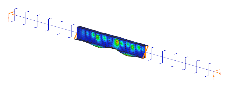
The Superbeam function offers a smart, adaptive way to handle structural members. It enables you to model with the simplicity of standard 7DOF beam elements while allowing you to switch to a more detailed shell-based analysis for specific members whenever needed.
Once the structure is modeled using beam elements, you can select how each member is analyzed:
- Using the beam model, which applies Consteel’s proven 7DOF beam elements along with its comprehensive design tools.
- Or using a shell model, which is automatically generated for selected members. This shell model includes detailing features such as web cutouts and stiffeners, fully integrated into the global analysis model.
This dual approach is fully adaptive. You can continue modifying your model using beam elements and switch between analysis modes as required, offering both speed and precision within the same workflow.
For a complete overview of how to activate and manage Superbeam functionality, refer to the documentation:
Superbeam – Consteel Manual


When you need complete control over geometry and mesh, or when shell analysis alone is not sufficient, Consteel provides the Convert members to plates function. This tool allows you to manually transform selected members into actual plate elements, enabling detailed modeling from the start.
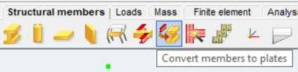
Unlike the automatic conversion used in Superbeam, this method performs a permanent, non-reversible transformation (though undo is available during the session). It supports a wide range of section types, including hot-rolled, cold-formed, and welded profiles.
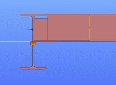
The conversion process preserves and adapts existing connections, eccentricities, loads, and supports. Where needed, rigid bodies and constraint elements are added to maintain structural continuity. These constraints ensure proper transfer of deformations, including warping, between the new plate model and the rest of the structure.
This function is especially useful in cases where precision is critical, such as modeling joints, fabrication-specific details, or complex load interactions.
To learn more, see the full guide here:
Convert Members to Plates – Consteel Manual
Both Superbeam and Convert members to plates serve different purposes, depending on the level of detail and control required in your model:
| Feature | Superbeam | Convert members to plates |
| Workflow | Beam modeling with optional shell analysis | Full plate modeling from the beginning |
| Conversion | Automatic and reversible | Manual and permanent |
| Suitable For | Flexibility in analysis, quick modeling | Full control, high-detail requirements |
| Supported Sections | Welded I and H profiles | Hot-rolled, cold-formed, and welded sections |
| Detailing Support | Cutouts and stiffeners (in shell analysis) | Full geometric detailing, including transitions |
| Design Integration | Integrated with beam-based design tools | Suitable for fabrication-level modeling |
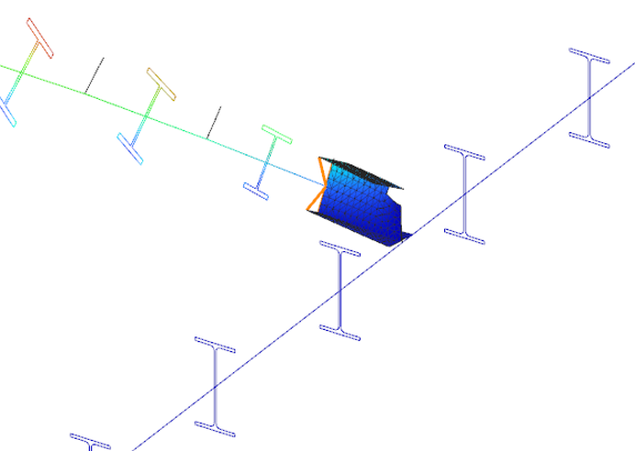
In Superbeam, constraint elements are generated automatically to connect converted shell elements to other members, such as bars. During member-to-shell conversion, these elements link the FE shell nodes to the rest of the model, ensuring accurate deformation transfer.
If the convert members to plate function is applied directly to beam elements, rigid bodies are created at their ends, which is useful for analyzing local behavior but does not transfer warping deformations. If the beam is first converted to a shell and then to plates, hinged rigid edges are placed along the plate boundaries. This arrangement, combined with constraint elements, transfers not only in-plane and out-of-plane deformations but also warping between the shell and the rest of the structure.
Download the example model and try it!
Download modelIf you haven’t tried Consteel yet, request a trial for free!
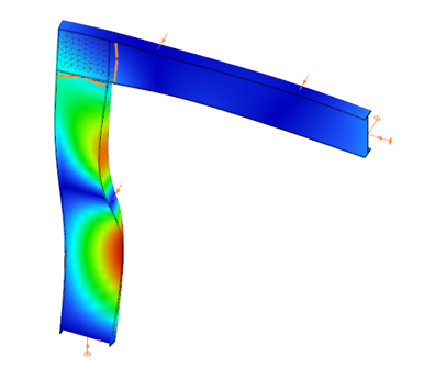
Try Consteel for freeDid you know that you could use Consteel to design web-tapered members?
Tapered members are widely used in the economic design of steel-framed structures, such as industrial halls and warehouses, because they make it possible to save material while still ensuring structural strength and stability. With Consteel’s dedicated Tapered Member function, you can model, analyze, and verify these members efficiently, supporting both everyday engineering practice and advanced stability checks.
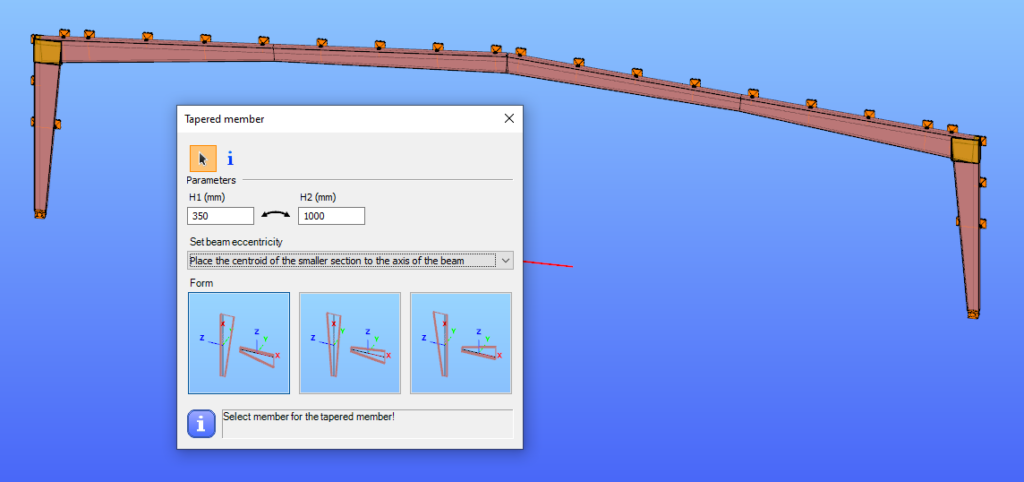
In Consteel, tapered members are line members with welded I or H, box, or cold-formed C sections. Hot-rolled and other macro sections cannot be tapered. Their section height can vary linearly along the member length, making them suitable for realistic structural modeling.
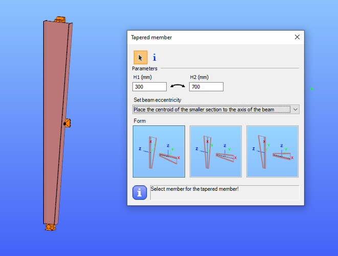
It is best to start with a section close to the smaller end of the taper. The start height (H1) applies at the beginning of the member, and the end height (H2) at the other end. If either value is less than half of the original section height, Consteel automatically resets it to 0.5 times the original. H1 and H2 can be swapped easily with the dedicated icon to reverse the taper direction.
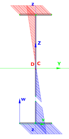
The placement of a tapered member relative to the axis of the original beam is defined by beam eccentricity rules. Consteel offers three alignment options:
- Centroid of the smaller section on the axis – the tapering develops outward from the end with the smaller height.
- Centroid of the larger section on the axis – the bigger end of the member remains fixed to the original axis.
- Centroid of the original section on the axis – one edge of the tapered member coincides with the original section, and the tapering starts from this position.
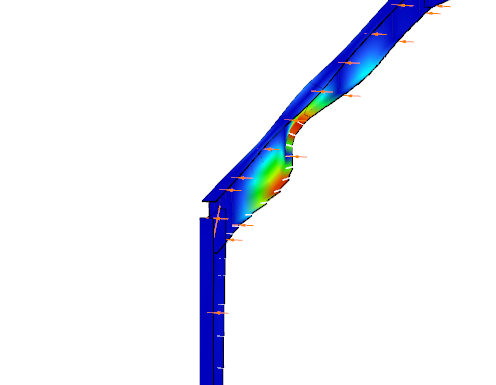
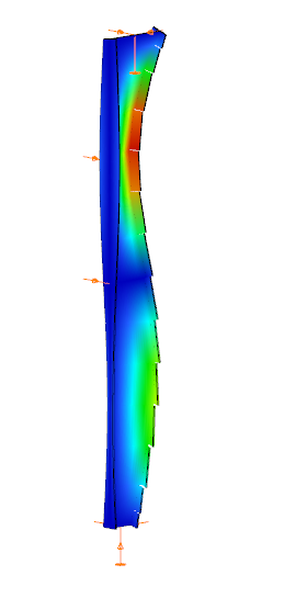
In analysis, Consteel creates tapered sections with the specified start and end heights and places them on the member’s reference line. Unless symmetric tapering is used, this placement is eccentric, which introduces additional effects. At frame joints, for example, extra moments from eccentric axial forces must be considered to maintain equilibrium.
Consteel handles these effects automatically, ensuring realistic results. Symmetric tapering keeps the analysis simpler, while eccentric tapering requires more attention. In all cases, global stability checks should complement sectional verifications to guarantee structural safety.
Download the example model and try it!
Download modelIf you haven’t tried Consteel yet, request a trial for free!
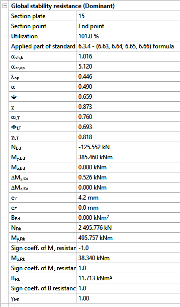
Try Consteel for freeDid you know that you could use Consteel to determine the optimum number of shear connectors for composite beams?
In composite beam design, the required number of shear studs is not only a detailing issue but a direct part of the structural resistance mechanism. The modelling and design environment in Consteel allows this number to be determined in a rational and automated way, consistent with EN 1994-1-1:2010.
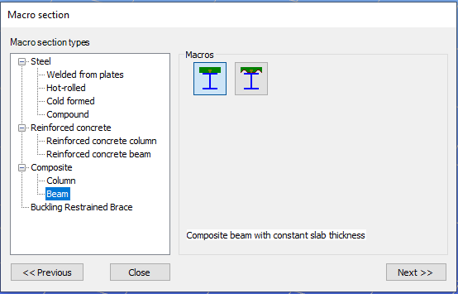
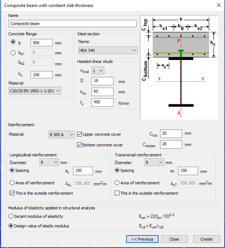
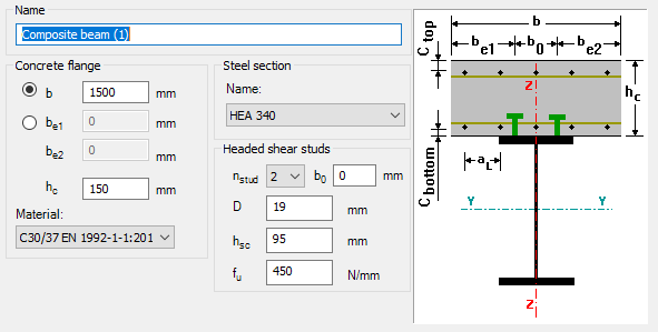
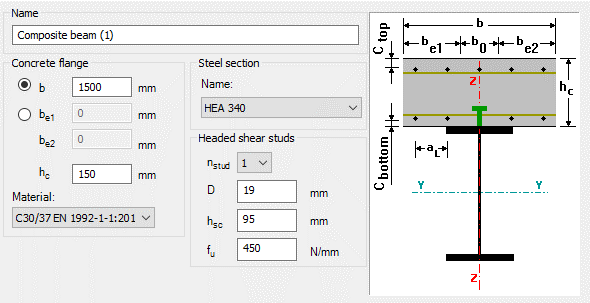
The process begins with the definition of a composite beam cross-section (Macro section). Two standard types are available: a solid slab composite beam and a profiled steel sheeting composite beam. The effective width is defined at input level, but the actual effective width used in analysis is calculated automatically based on span, geometry, and stud spacing assumptions. This ensures that the structural response is captured realistically, while maintaining simple input control for the user.
After defining the cross-section, the member is created and design parameters are assigned through object properties. These parameters govern key aspects of composite behaviour, including stud spacing, support conditions, and whether shear stud design is performed manually or automatically.
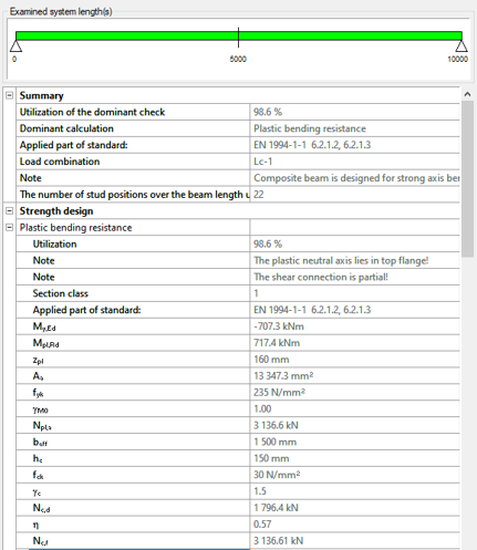
For shear connector design, Consteel applies a plastic distribution model. The governing section of the beam, typically corresponding to the maximum bending moment, is identified automatically. From this section, shear studs are distributed symmetrically along the beam length.
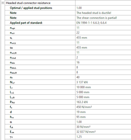
When automatic optimisation is selected, the software determines the minimum number of shear studs required to satisfy bending resistance. It then increases the number iteratively until the composite section achieves sufficient capacity. The resulting value represents the optimal number of shear connector positions for the given loading and geometry.

The key parameters used in this evaluation include:
- nopt: optimal number of shear stud positions in the governing region
- nact: actual number of stud positions applied
- sL, sR: spacing of studs on the left and right side of the critical section
- nmin: minimum required number of stud positions based on resistance
The ratio nact / nopt is used as a direct measure of utilisation of the shear connector system.
There is also the option to define the number of studs manually. In that case, Consteel distributes them uniformly along the member and checks compliance with detailing rules such as minimum and maximum spacing. This is typically useful when construction constraints or predefined detailing standards take priority.
Composite beam design itself is carried out according to EN 1994-1-1:2010. Plastic bending resistance is evaluated for Class 1 and 2 cross-sections, while shear, concrete flange crushing, and longitudinal shear are checked at critical sections. Shear buckling is treated according to EN 1993-1-5. Lateral-torsional buckling is not included in the current design scope.
For profiled sheeting, shear stud resistance is reduced depending on rib orientation, in line with Eurocode 4 rules.
Overall, the key point is that the number of shear connectors is no longer an assumed input. It is derived from structural demand through an automated and transparent process, which makes it easier to reach an efficient and consistent composite design without repeated manual iteration.
Download the example model and try it!
Download modelIf you haven’t tried Consteel yet, request a trial for free!
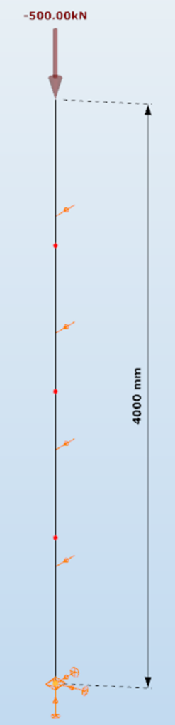
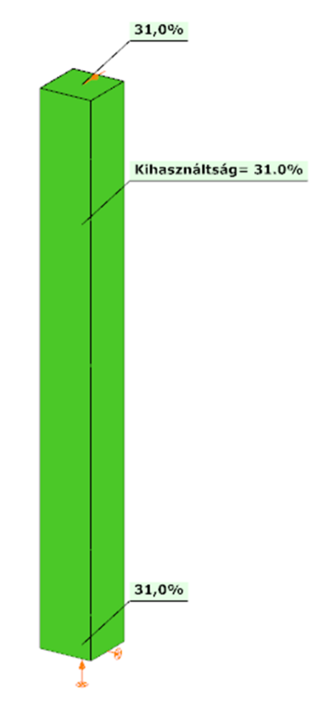
Try Consteel for freeDid you know that you could use Consteel to determine automatically the second order moment effects for slender reinforced concrete columns?
Download the example model and try it!
Download modelIf you haven’t tried Consteel yet, request a trial for free!
Try Consteel for free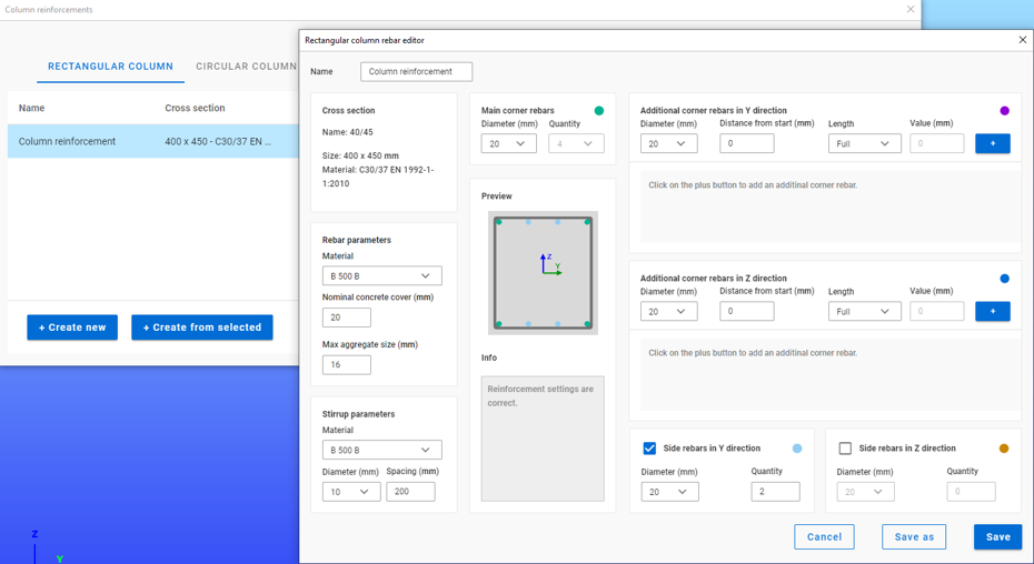
Bevezető
Szabályok segítségével történő teherkombináció szűrés esetén a leggyakrabban használt kihasználtsági típus az Acél – mértékadó vizsgálat. Milyen eredményeket vesz figyelembe pontosan ez az opció és mit jelentenek a hozzá kapcsolódóan választható korlátok?
A teherkombinációk szűrésének négy módja van: határállapotok, teheresetek alapján, kézzel vagy szabályok alkalmazásával. A három másik módszerrel ellentétben a szabályok szerinti szűrés kizárólag számítási eredmények alapján lehetséges.
A teherkombinációk számának csökkentésének leghatékonyabb módja minden bizonnyal a kihasználtsági szabályok alkalmazása.
Kihasználtsági szabályok segítségével a teherkombinációkat az általuk okozott kihasználtságok alapján választjuk ki. A kihasználtságok a különböző tervezési vizsgálatokban elérhetők, mértékadó eredményekből és acél szelvények esetén az egyes vizsgálatokból is, úgy mint általános rugalmas szilárdsági ellenállás, tiszta igénybevételi ellenállások, interakció és globális stabilitás vizsgálat.

A mértékadó vizsgálat jelentése
A mértékadó vizsgálat nem mindig az a vizsgálat, amelyik a legnagyobb kihasználtságot adja, hanem az, amelyik a legnagyobb RELEVÁNS kihasználtságot. Tipikus példa erre, amikor a képlékeny interakciós képletek érvényesek, akkor ez lesz a mértékadó vizsgálat az általános rugalmassal szemben, jóllehet ez utóbbi magasabb kihasználtságokat ad.
Acél – Mértékadó vizsgálat
Az Acél – Mértékadó vizsgálat opció minden végeselem ponthoz tartalmazza a mértékadó vizsgálatból származó kihasználtságot minden kombinációban. Ez azt jelenti, hogy pontonként annyi kihasználtsági értékünk lesz, ahogy teherkombinációt kiszámoltunk.
Fontos megérteni a különbséget a Mértékadó eredmények maximuma és az Acél – Mértékadó vizsgálat opció között. A Mértékadó eredmények maximuma opció a mértékadó teherkombináció mértékadó vizsgálatból származó kihasználtságot tartalmazza minden pontban, mintegy burkolója az Acél – Mértékadó vizsgálat eredményeinek. Vagyis itt minden végeselem ponthoz egyetlen kihasználtság (és egy teherkombináció) tartozik. Egyben megegyezik a Globális vizsgálatok fülön megjelenő mértékadó eredmények táblázattal.
Amikor egy szabályt alkalmazunk, a kiválasztott kihasználtsági típushoz tartozó kihasználtságokat összevetjük a megadott korláttal. Azok a teherkombinációk, amelyekből származó eredmények megfelelnek a korlátnak, kiválasztásra kerülnek. A vizsgálat a választott modell részlet minden végeselem pontjában megtörténik.
Korlátok Acél – Mértékadó vizsgálat opció esetén
- Maximum: azon kombinációk kiválasztására, amelyek bárhol a legnagyobb kihasználtságot okozzák. Lehet ugyanaz, mint a Mértékadó eredmények maximuma, kivéve amikor vannak olyan kombinációk, ahol a kihasználtság ugyanannyi, és az a mértékadó. Ilyenkor itt az összes ilyen teherkombináció kiválasztásra kerül, míg a Mértékadó eredmények maximuma opciónál mindig csak egy mértékadó van.
- Több mint a legnagyobb érték %-a: ugyanazokat a kombinációkat választja ki, mint a Maximum és még azokat, amelyek az adott pontbeli legnagyobb kihasználtság adott százaléka feletti kihasználtságot eredményeznek. Például ha egy adott pontban a mértékadó kihasználtság 80%, a kihasználtsági szabály korlátja pedig ‘Több mint a legnagyobb érték 90%-a’, akkor ez a szabály ki fogja választani az összes olyan teherkombinációt, ami ebben a pontban 0,9*80%=72% és 80% közötti kihasználtságot eredményez.
- Több mint: kiválasztja azokat a teherkombinációkat, amelyek bárhol a megadott érték feletti kihasználtságot eredményeznek.
Nézzünk egy egyszerű síkbeli keretet példaként a jobb érthetőség kedvéért. A jobb oldali gerendát egy részletbe raktuk, amire három kihasználtsági szabályt alkalmaztunk. Öt pontot a bemutatás kedvéért kiválasztottunk, de természetesen a részletmodell minden pontja figyelembe van véve a szűrésnél.

Bevezetés
A ConSteel-ben három lehetőség áll rendelkezésre vasbeton oszlopok tervezésére: Manuális névleges görbület módszer, automatikus névleges görbület módszer és névleges merevség módszer.
Mindegyik módszernek megvannak az előnyei és a hátrányai, és különböző esetekben érdemes használni őket. Most röviden áttekintjük ezeket a módszereket és bemutatjuk hogyan használhatóak. Egy példamodell csomag és egy segítő folyamatábra is elérhető az áttekintés végén.
Az említett módszerekhez köthető funkciók elérése az Online Kézikönyvünk Structural design és Structural modeling fejezeteiben található meg.
Áttekintő táblázat
A következő táblázat röviden tartalmazza a legfontosabb információkat. Kattints a táblázatra a teljes képernyős megtekintéshez.

Most egy-egy rövid példán keresztül bemutatjuk a módszerek alkalmazását.
Példák
Manuális Névleges Görbület Módszer
Szelvény létrehozása
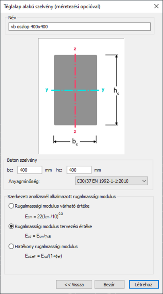
Imperfekciók nélküli szerkezet definiálása
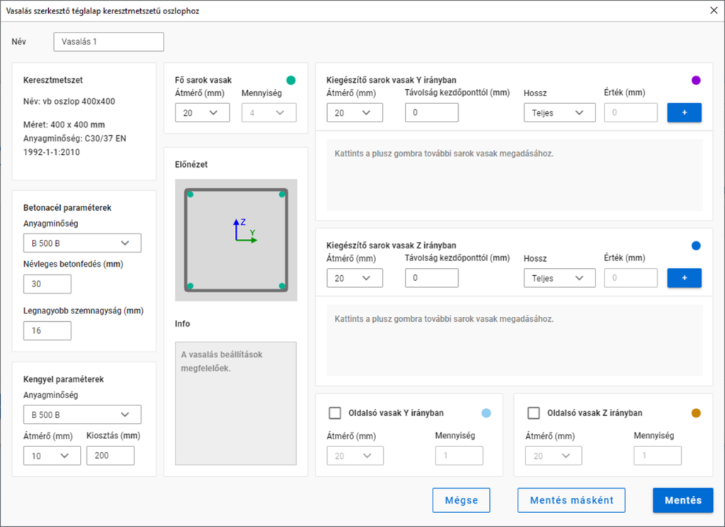
Vasalás definiálása
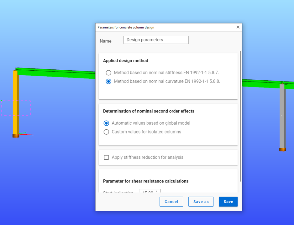
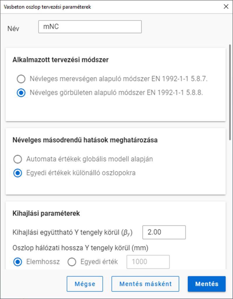
Tervezési paraméterek megadása
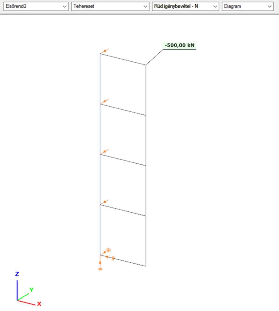
Elsőrendű analízis
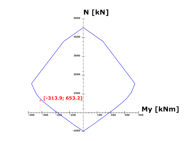
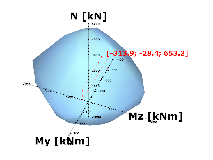
Tervezés

Automatikus Névleges Görbület Módszer
A manuális névleges görbület módszerhez képest eltérő lépéseket mutatjuk be.
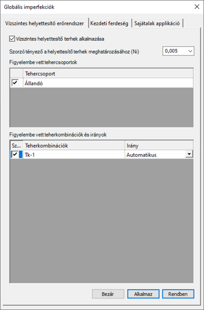
Imperfekciók definiálása
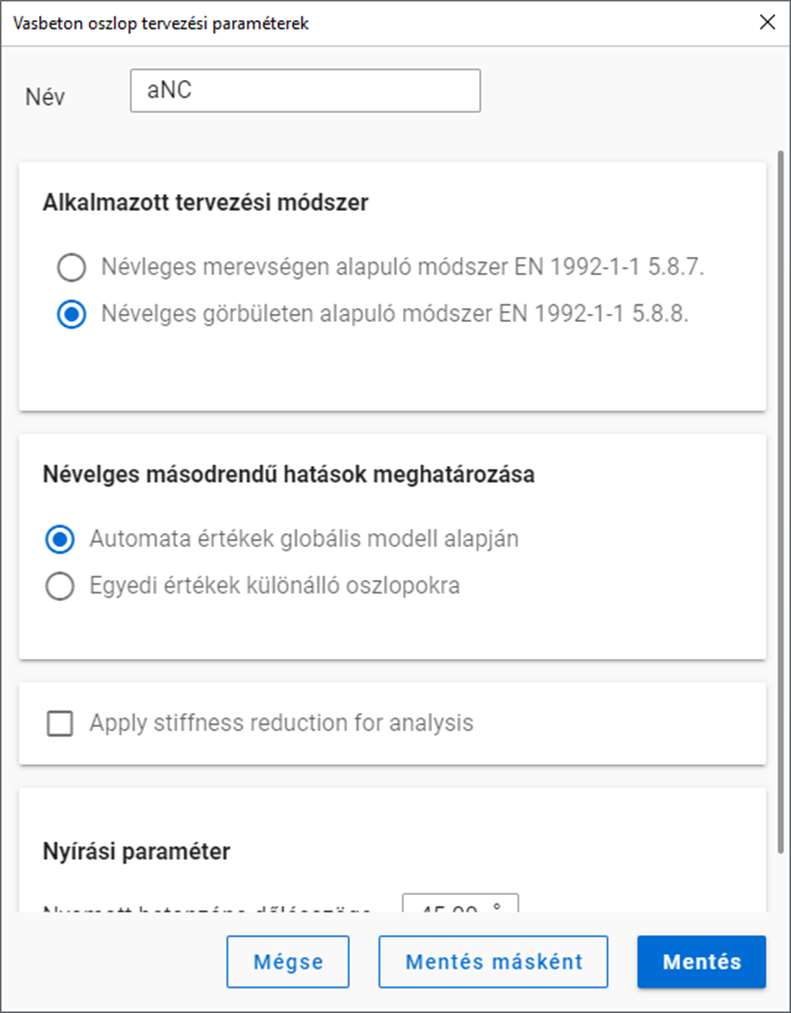
Tervezési paraméterek megadása
Elsőrendű analízis – imperfekciókkal együtt
gate