
- Contents
Secret formulas of EN 1993-1-3 Part 1
EN 1993-1-3 contains 3 „secret” formulas. The first two are used to determine the effective cross section due to distortional buckling when edge or intermediate stiffeners are involved. The third is used to calculate the distortion of the whole cross section when analyzed with a connected sheeting.
The physical meaning of all three formulas can be easily shown with simple ConSteel models which helps designer to understand the underlaying mechanial model.


The first formula (5.10) is used when the ability of an edge stiffener to stabilize a compressed flange of Z or C section is studied. During distortional buckling the intersection point of flange with the lip (it is called as edge stiffener) is expected to move in a direction perpendicular to the flange. This formula gives the stiffness value provided by the Z or C section, when is assumed that during deformations the point of intersection of the web with the flange doesn’t move. This assumption corresponds to attaching supports to these nodes as seen on picture 5.6 of EN 1993-1-3.
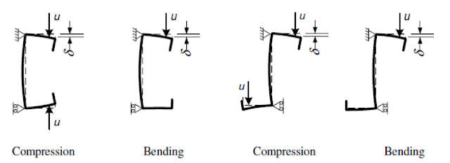
When a compressed edge stiffener would buckle, it will be partially restrained by the section with these attached supports. Depending on the distribution of normal stresses on the section, one or two edge stiffeners might be under compression. If both stiffeners are under compression and tend to buckle, the restraining capacity of the section will have to be shared between them. This sharing requirement is reflected by the coefficent kf. The spring stiffness value will be used as a distributed spring support when the buckling resistance of the edge stiffener is calculated.
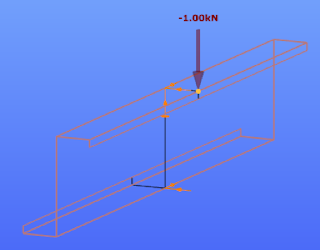
Stiffness values are typically calculated as the ratio of a displacements obtained from the application of a unit load. In this case the unit loads are applied parallelly to the expected displacement of the compressed edge stiffeners.
The ConSteel model shown below reproduces the stiffness calculation for a 1 m long Zee section (as a simplification the unit loads are placed at the intersection of the flange with the lip and not at the center of the gravity of the edge zone):
Z purlin, nominal thickness = 1.30 mm, 200 mm deep, 72 mm wide symmetric flanges, 15.5 mm deep lips
in case of My bending: kf = 0, b1 = b2 = 72 mm, hw = 198.7 mm, t = 1.26 mm
K1 = 210000*1.26^3/4*(1-0.3^2)*1/(72^2*198.7+72^3+0.5*72*72*198.7*1.0) = 0.08 N/mm2
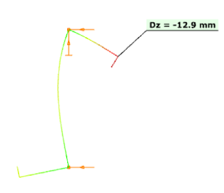
The resulting vertical displacement from the point load is 12.9 mm.

Log in to view this content
Online service access and support options are based on subscription plans. Log in to view this content or contact our sales department to upgrade your subscription. If you haven’t tried Consteel yet, try for free and get Pro access to our learning materials for 30 days!