Introduction
This verification example studies a simple fork supported beam member with welded section equivalent to IPE360 (flanges: 170-12,7; web: 347-8) subjected to biaxial bending due to concentrated end moments and compression due to axial force. Second order deformations of the middle cross-section of the member are calculated by hand and by the ConSteel software using both 7DOF beam and shell finite elements and Superbeam function. In addition to the verification, the difference between modelling with 6DOF and 7DOF elements is demonstrated.
Geometry

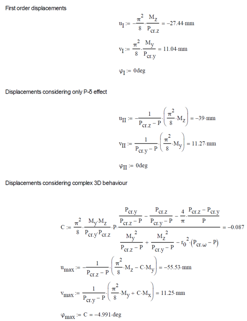
Calculation by hand
The first order and the simple amplified (P-δ) deformations can be analitically calculated by the well known formulas. The calculation of the second order deformations considering true, three-dimensional behaviour of the beam is however so complicated that there are only approximate analitical formulas available for hand calculation. The formula below can be found in Chen, W. and Atsuta, T.: Theory of Beam-Columns, Vol. 2: Space behavior and design, McGRAW-HILL 1977, p. 192


Computation by Consteel
Version nr: Consteel 15 build 1722
First order

Second order – 6DOF beam element
The second order deformation of the member which was computed by the ConSteel software. It is visible that there is no torsion, only increments of the lateral displacements due to P-δ effect:

Second order – 7DOF beam element
The second order deformation of the member which was computed by the ConSteel software using the 7DOF beam finite element model (n=16). It is visible that there is torsion and further increment in the lateral displacement (Dy):

Second order – Shell finite element
The second order deformation of the member which was computed by the ConSteel software using the shell finite element model (δ=25mm):

Second order – Superbeam
The second order deformation of the member which was computed by the ConSteel software using the Superbeam model (δ=25mm):

Critical temperature calculation in Consteel
The calculation of the critical temperature is available in Consteel since the release of version 14. As an introduction of this feature, we prepared a video that gives some theoretical background on the topic, and demonstrates its usage in Consteel. It is shown how to prepare the model, how to execute the analysis and design, and how to create documentation about the critical temperature results.
Check out our user guide to learn more!
gate