The practical use of the ‘General method’ of EN 1993-1-1 6.3.4 for the buckling design of global structural models is still a challenging issue requiring several problems to solve. In this paper we propose a fully developed methodology presenting solutions for the application topics such as the suitable FE model, specific modeling issues to capture the true 3D behavior of the members and the whole model and the final evaluation of the design parameters. The presented methodology consistently uses a unique model for the evaluation of all analysis and design parameters and results and yields a fully automatic design process controlled solely by the properly created structural model.
Click the button bellow to download and read the full article.
gateIntroduction
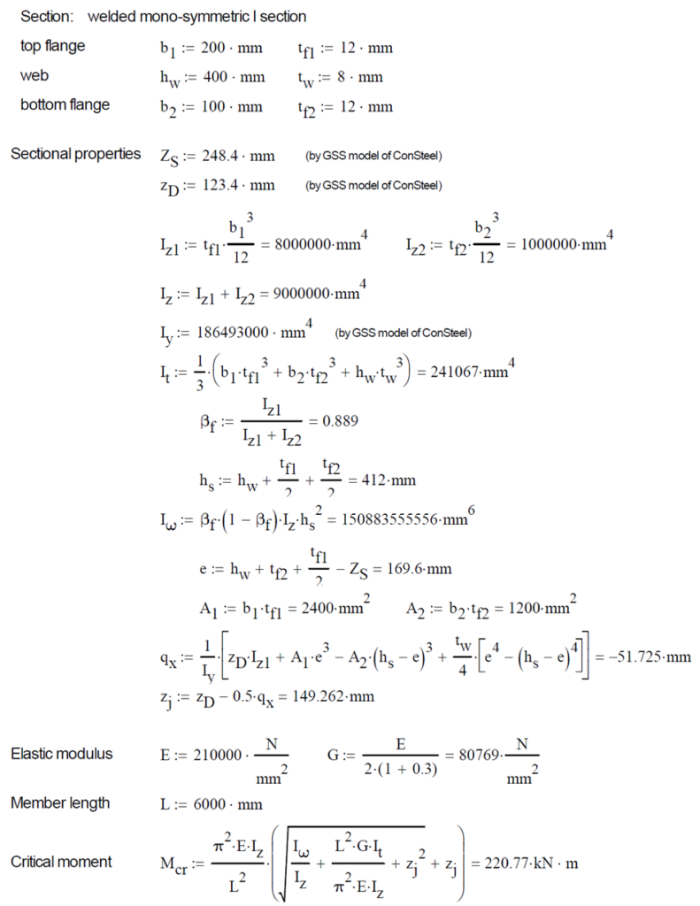
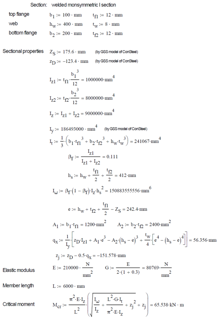
This verification example studies a simple fork supported beam member with welded section (flanges: 200-12 and 100-12; web: 400-8) subjected to bending about major axis. Constant bending moment due to concentrated end moments and triangular moment distribution from concentrated transverse force is examined for both orientations of the I-section. Critical moment and force of the member is calculated by hand and by the Consteel software using both 7 DOF beam finite element model and Superbeam function.
Geometry
Normal orientation – wide flange in compression
Constant bending moment distribution

Triangular bending moment distribution – load on upper flange

Triangular bending moment distribution – load on bottom flange

Reverse orientation – narrow flange in compression
Constant bending moment distribution

Triangular bending moment distribution – load on upper flange

Triangular bending moment distribution – load on bottom flange

Calculation by hand
Factors to be used for analitical approximation formulae of elastic critical moment are taken from G. Sedlacek, J. Naumes: Excerpt from the Background Document to EN 1993-1-1 Flexural buckling and lateral buckling on a common basis: Stability assessments according to Eurocode 3 CEN / TC250 / SC3 / N1639E – rev2
Normal orientation – wide flange in compression
Constant bending moment distribution


Reverse orientation – narrow flange in compression


Computation by Consteel
Version nr: Consteel 15 build 1722
Normal orientation – wide flange in compression
Constant bending moment distribution
- 7 DOF beam element
First buckling eigenvalue of the member which was computed by the Consteel software using the 7 DOF beam finite element model (n=25). The eigenshape shows lateral torsional buckling.

Superbeam
First buckling eigenvalue of the member which was computed by the Consteel software using the Superbeam function (δ=25).

Introduction
This verification example studies a simple fork supported beam member with welded section equivalent to IPE360 (flanges: 170-12,7; web: 347-8) subjected to biaxial bending due to concentrated end moments and compression due to axial force. Second order deformations of the middle cross-section of the member are calculated by hand and by the ConSteel software using both 7DOF beam and shell finite elements and Superbeam function. In addition to the verification, the difference between modelling with 6DOF and 7DOF elements is demonstrated.
Geometry

Calculation by hand
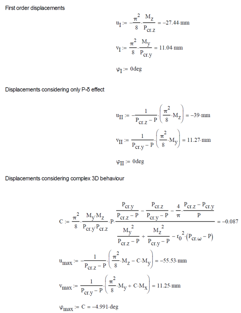
The first order and the simple amplified (P-δ) deformations can be analitically calculated by the well known formulas. The calculation of the second order deformations considering true, three-dimensional behaviour of the beam is however so complicated that there are only approximate analitical formulas available for hand calculation. The formula below can be found in Chen, W. and Atsuta, T.: Theory of Beam-Columns, Vol. 2: Space behavior and design, McGRAW-HILL 1977, p. 192


Computation by Consteel
Version nr: Consteel 15 build 1722
First order

Second order – 6DOF beam element
The second order deformation of the member which was computed by the ConSteel software. It is visible that there is no torsion, only increments of the lateral displacements due to P-δ effect:

Second order – 7DOF beam element
The second order deformation of the member which was computed by the ConSteel software using the 7DOF beam finite element model (n=16). It is visible that there is torsion and further increment in the lateral displacement (Dy):

Second order – Shell finite element
The second order deformation of the member which was computed by the ConSteel software using the shell finite element model (δ=25mm):

Second order – Superbeam
The second order deformation of the member which was computed by the ConSteel software using the Superbeam model (δ=25mm):

