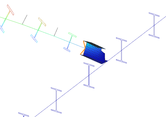
Did you know that you could use Consteel to perform dual analysis with 7DOF beam and/or shell elements?
With two advanced features, Superbeam and Convert members to plates, you can choose the approach that best suits your project needs, whether you’re focused on modeling efficiency or detailed analysis.
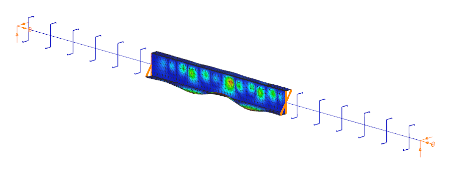
The Superbeam function offers a smart, adaptive way to handle structural members. It enables you to model with the simplicity of standard 7DOF beam elements while allowing you to switch to a more detailed shell-based analysis for specific members whenever needed.
Once the structure is modeled using beam elements, you can select how each member is analyzed:
- Using the beam model, which applies Consteel’s proven 7DOF beam elements along with its comprehensive design tools.
- Or using a shell model, which is automatically generated for selected members. This shell model includes detailing features such as web cutouts and stiffeners, fully integrated into the global analysis model.
This dual approach is fully adaptive. You can continue modifying your model using beam elements and switch between analysis modes as required, offering both speed and precision within the same workflow.
For a complete overview of how to activate and manage Superbeam functionality, refer to the documentation:
Superbeam – Consteel Manual

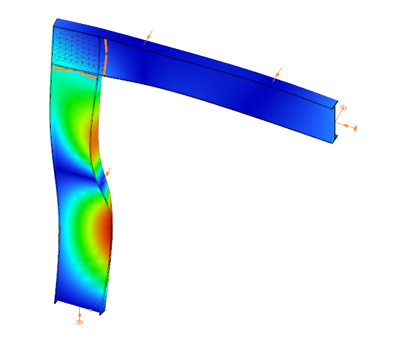

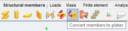
When you need complete control over geometry and mesh, or when shell analysis alone is not sufficient, Consteel provides the Convert members to plates function. This tool allows you to manually transform selected members into actual plate elements, enabling detailed modeling from the start.
Unlike the automatic conversion used in Superbeam, this method performs a permanent, non-reversible transformation (though undo is available during the session). It supports a wide range of section types, including hot-rolled, cold-formed, and welded profiles.
The conversion process preserves and adapts existing connections, eccentricities, loads, and supports. Where needed, rigid bodies and constraint elements are added to maintain structural continuity. These constraints ensure proper transfer of deformations, including warping, between the new plate model and the rest of the structure.
This function is especially useful in cases where precision is critical, such as modeling joints, fabrication-specific details, or complex load interactions.
To learn more, see the full guide here:
Convert Members to Plates – Consteel Manual
Both Superbeam and Convert members to plates serve different purposes, depending on the level of detail and control required in your model:
| Feature | Superbeam | Convert members to plates |
| Workflow | Beam modeling with optional shell analysis | Full plate modeling from the beginning |
| Conversion | Automatic and reversible | Manual and permanent |
| Suitable For | Flexibility in analysis, quick modeling | Full control, high-detail requirements |
| Supported Sections | Welded I and H profiles | Hot-rolled, cold-formed, and welded sections |
| Detailing Support | Cutouts and stiffeners (in shell analysis) | Full geometric detailing, including transitions |
| Design Integration | Integrated with beam-based design tools | Suitable for fabrication-level modeling |
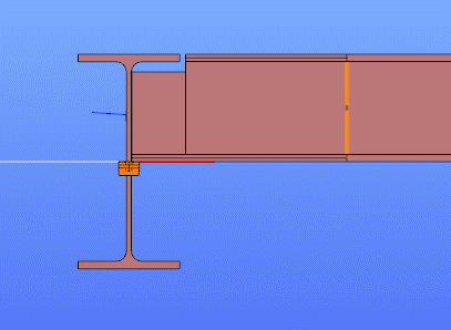
In Superbeam, constraint elements are generated automatically to connect converted shell elements to other members, such as bars. During member-to-shell conversion, these elements link the FE shell nodes to the rest of the model, ensuring accurate deformation transfer.
If the convert members to plate function is applied directly to beam elements, rigid bodies are created at their ends, which is useful for analyzing local behavior but does not transfer warping deformations. If the beam is first converted to a shell and then to plates, hinged rigid edges are placed along the plate boundaries. This arrangement, combined with constraint elements, transfers not only in-plane and out-of-plane deformations but also warping between the shell and the rest of the structure.
Download the example model and try it!
Download modelIf you haven’t tried Consteel yet, request a trial for free!
Try Consteel for freeDid you know that you could use Consteel to consider connection stiffness for global analysis?
One of Consteel’s unique strengths is its ability to integrate joint modeling and calculation directly into the global analysis.
The Joint module performs all analyses in line with the standard procedures of Eurocode 3 Part 1-8, covering almost the entire scope of the code. This ensures results that are both reliable and fully compliant, across a wide range of connection types such as: Moment connections, Shear connections, Hollow section connections.
Modern structural design increasingly considers the mechanical interaction between the global model and its joints — whether rigid, semi-rigid, or pinned.
If you’d like to dive deeper into how semi-rigid joints influence structural behavior and stiffness classification, check out our detailed article: Semi-rigid joints in modeling of structures.
This integrated approach leads to results that are both more realistic and more economical, but it also requires more sophisticated modeling. Consteel makes this process straightforward:
- Joints can be created manually or automatically based on the model geometry.
- The create joint by model function examines member positions and cross-sections, then offers suitable joint types.
- Once defined, the joint can be placed into the global model, and its connection stiffness can be included in the global analysis.
- After placement, the joint is always rechecked against the latest analysis results.
In order to consider the connection stiffness of the placed joint, open the analysis parameters, tick the Include connection stiffness checkbox, and rerun the analysis.
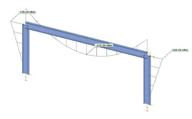
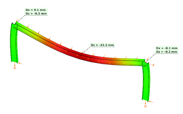
Let’s explore how the behavior of a simple frame changes under different connection assumptions:
In the first case, where no actual connection stiffness was considered and the members were assumed to have continuous rigid ends, the results showed a bending moment (My) of 129.23 kNm at the column upper end and 115.25 kNm at the beam midspan. The corresponding deflection in the beam’s midspan (z-direction) was –17.4 mm.
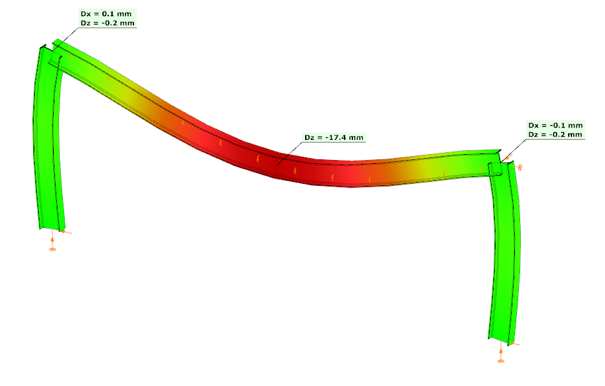
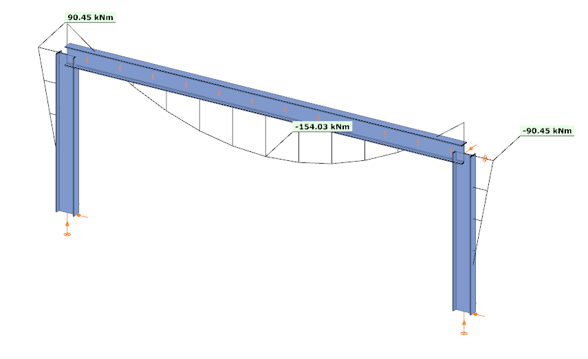
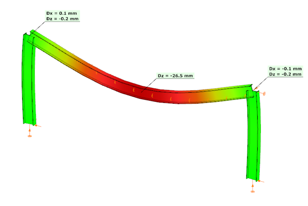
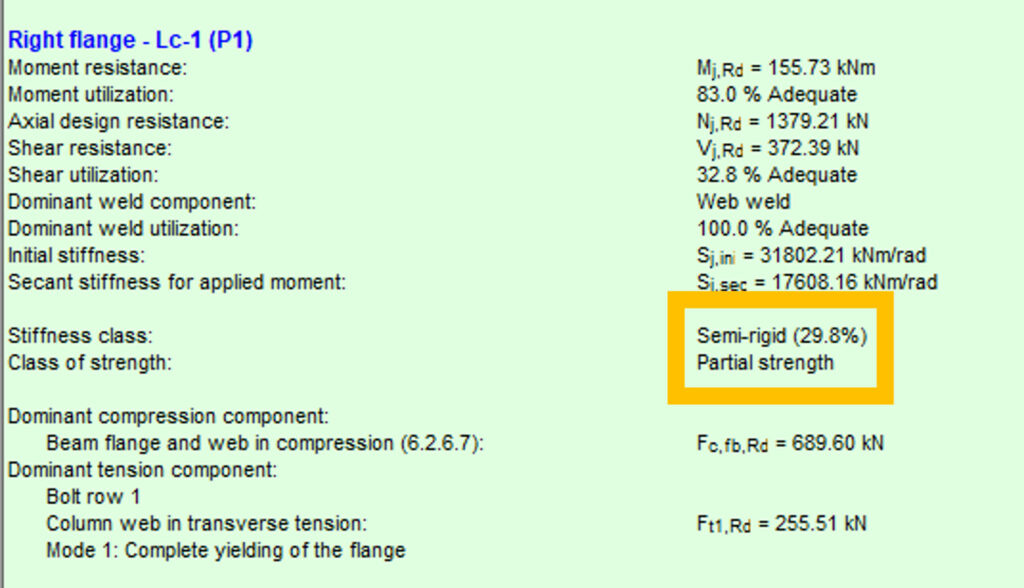
In the second case, the connections were modeled with their actual semi-rigid stiffness of 29.8% and partial strength. Here, the bending moment at the column upper end decreased to 90.45 kNm, while the beam midspan moment increased to 154.03 kNm. The beam midspan deflection reached –26.5 mm, representing an increase of 52% compared to the rigid assumption.
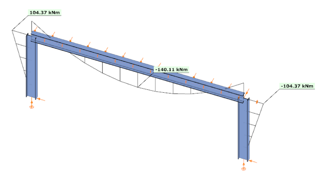
In the third case, with a higher semi-rigid stiffness of 53.6% and partial strength, the results balanced between the two extremes: the column end moment was 104.37 kNm, the beam midspan moment was 140.11 kNm, and the midspan deflection was –23.2 mm. This corresponds to an increase of 33% in deflection compared to the rigid assumption.

These examples clearly demonstrate how connection stiffness significantly influences global structural behavior. Assuming rigid connections may underestimate beam deflections and distort moment distribution, while considering realistic semi-rigid stiffness, provides a more accurate representation of structural performance.
Download the example model and try it!
Download modelIf you haven’t tried Consteel yet, request a trial for free!
Try Consteel for freeDid you know that you could use Consteel to determine automatically the second order moment effects for slender reinforced concrete columns?
Download the example model and try it!
Download modelIf you haven’t tried Consteel yet, request a trial for free!
Try Consteel for free
Did you know that you could use Consteel to calculate effective cross-section properties for Class 4 sections?
The classification of cross-sections is used to understand how local buckling affects the strength and rotation capacity of structural members. As stated in Eurocode 3 (EN 1993-3-3, Section 5.5), this classification helps determine whether a cross-section can reach its full resistance or if its behavior is limited by local instability.
Class 4 cross-sections are those in which local buckling occurs before the material reaches the yield stress in one or more parts. Because of this, their resistance must be calculated using effective section properties that take into account the reduction caused by local buckling.
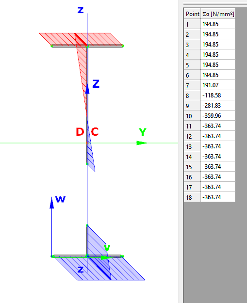
Typical Class 4 sections are characterized by slender elements with high width-to-thickness ratios. These commonly include thin webs or flanges, hollow sections (RHS/CHS) with slender walls, thin-walled cold-formed profiles such as C- or L-sections, and welded I-sections with slender webs. In this example, we consider a welded I-section with the following geometric parameters:
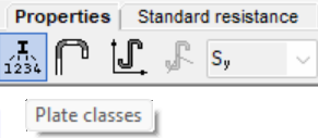
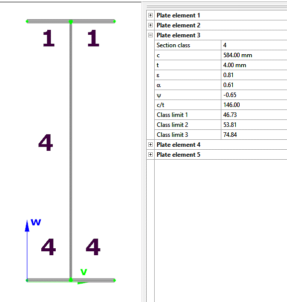
In Consteel, we can then see the section classification from the Global Checks tab. After selecting the investigated section either in the model or from the table and clicking on the Calculate Section option, and then choosing the Plate Classes in the Properties tab.
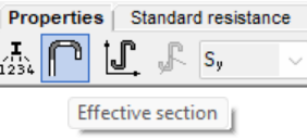
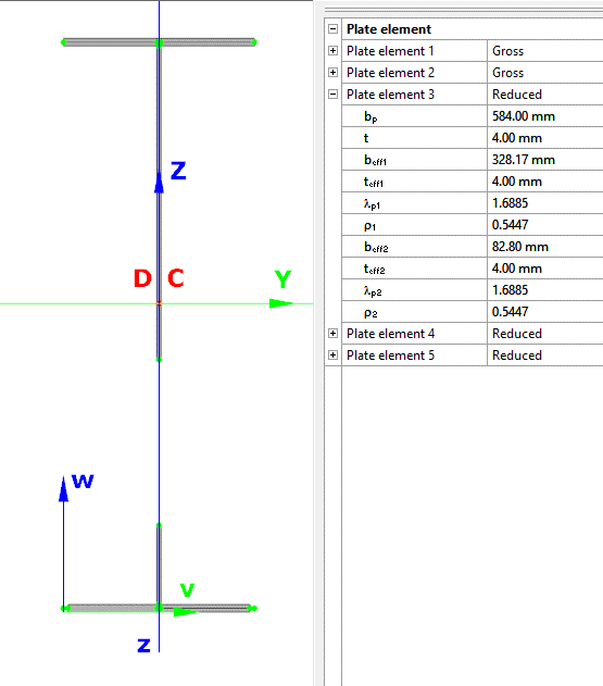
The effective section properties can then be viewed using the second option in the Properties tab.
In addition, stresses can be visualized by clicking on the Stresses icon. They can be represented either as a colored figure or as a 3D diagram.
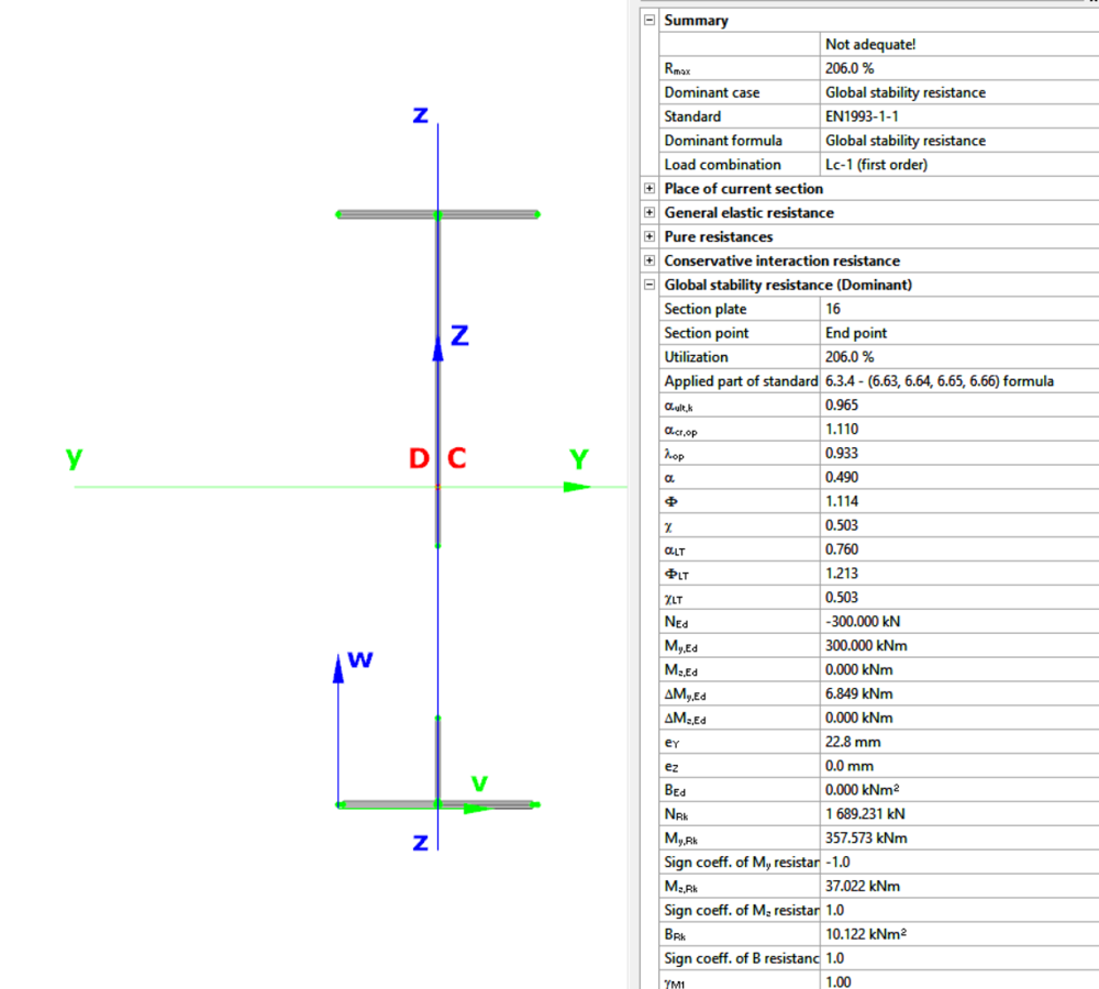
For Class 4 sections, the Standard Resistance tab in the section module provides a complete assessment for the selected loading case.
The section module performs all necessary calculations according to the Eurocode (EN 1993-1-1 and relevant parts of EN 1993-1-5), including general elastic resistance, pure case resistance, conservative interaction checks, and web buckling analysis.
All resistances are calculated using the effective section properties to account for local buckling, and the module identifies the dominant case to ensure all relevant checks are covered.
Download the example model and try it!
Download modelIf you haven’t tried Consteel yet, request a trial for free!
Try Consteel for freeDid you know that you could use Consteel to Consider the shear stiffness of a steel deck as stabilization for steel members?
In many practical steel structures, trapezoidal decking is treated only as a load-bearing surface. In reality, when properly connected to the supporting members, it behaves as a shear diaphragm and contributes to the overall stability of the structure. This effect can be directly taken into account in Consteel by applying shear field stiffness to beam elements.

The stabilizing effect comes from the in-plane shear stiffness of the deck. Under horizontal loading, the sheeting deforms and transfers forces between structural members. This behavior can be described by a single parameter, the shear stiffness (S), which represents the resistance of the diaphragm against deformation.
The overall stiffness is influenced by several components, including the shear deformation of the sheet, profile geometry, fastener slip, and connection flexibility. These contributions together define how effectively the deck can restrain phenomena such as lateral-torsional buckling.
A key requirement for this behavior is proper fastening. Typically, the sheeting must be connected along its edges and fixed to supporting members at each rib to ensure reliable diaphragm action.
In engineering practice, shear stiffness is determined using standardized or manufacturer-based methods rather than detailed analytical models. Consteel supports several established approaches:
- Schardt/Strehl method (DIN 18807), based on parameters describing shear and warping deformation
- Improved Schardt/Strehl method, including the effect of fastener spacing
- Bryan/Davies method, considering additional structural parameters
- Eurocode-based method, using general geometric properties of the sheeting
These methods differ in complexity and required input data, but all aim to provide a realistic stiffness value for use in global analysis. If the sheeting is not fixed at every rib, the calculated stiffness must be reduced accordingly.
The shear field object in Consteel allows engineers to include the diaphragm effect without detailed shell modeling. The calculated shear stiffness can be assigned directly to beam elements, providing additional lateral restraint.
The process involves selecting a trapezoidal sheet profile, choosing the appropriate calculation method, and defining the relevant geometric and connection parameters. The software then determines the stiffness and incorporates it into the structural model.
Including shear stiffness in the analysis can lead to higher critical load factors and reduced displacements, resulting in more efficient structural designs. However, it also means that the decking becomes part of the stabilizing system.
Any later modifications to the sheeting, such as openings or changes in fastening, may reduce this effect and should therefore be carefully assessed.
The shear stiffness of trapezoidal steel decking provides a measurable and often significant contribution to structural stability. By incorporating this effect in Consteel, engineers can achieve more realistic analysis results and optimize their designs while maintaining structural safety.
Download the example model and try it!
Download modelIf you haven’t tried Consteel yet, request a trial for free!
Try Consteel for freeDid you know that you could use Consteel to perform structural analysis at room and elevated temperatures as part of design process for fire resistance?
In structural fire engineering, the mechanical response of steel structures must be evaluated under both room and elevated temperature conditions. Consteel permits this by incorporating temperature-dependent material behavior directly into the finite element analysis, allowing engineers to assess not only resistance but also changes in global structural response.
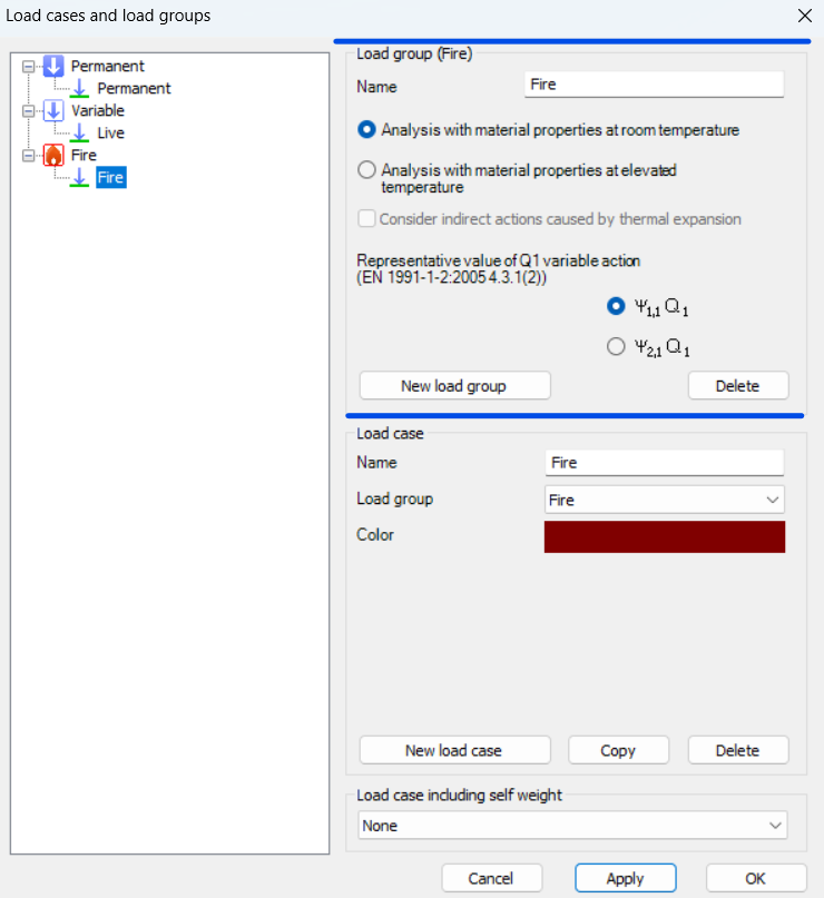
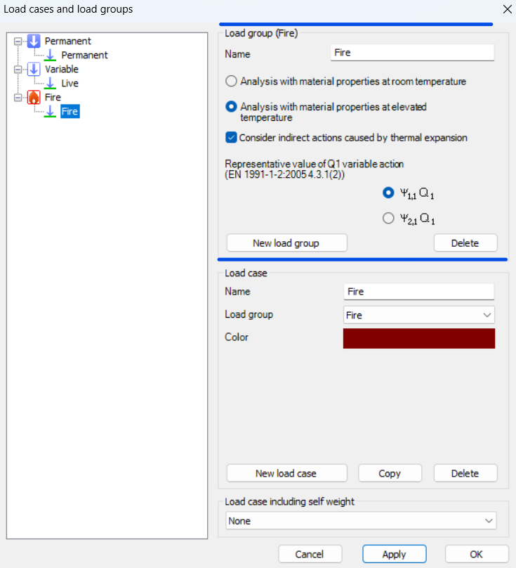
During fire analysis, Consteel determines the steel temperature and applies the corresponding reduction in material properties, most notably the modulus of elasticity and yield strength. These reductions are defined according to Eurocode 3 (EN 1993-1-2). As a result, the calculated internal forces and deformations reflect both the applied loads and the effects of thermal expansion and stiffness degradation. The analysis is performed on the global structural model, so compatibility effects and force redistribution are inherently captured.
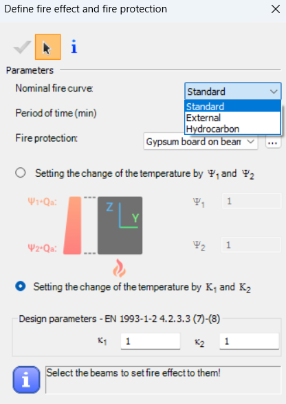
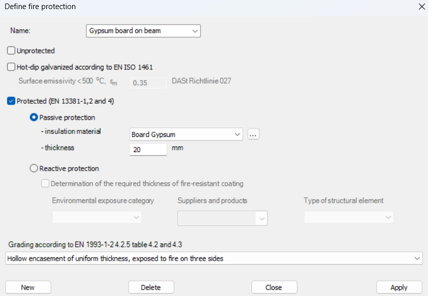
Fire exposure is defined using nominal fire curves (Standard, External, Hydrocarbon), together with a specified fire resistance time. In addition, the model allows assignment of fire protection conditions, including unprotected members, hot-dip galvanized surfaces, and protected elements with either passive insulation or reactive (intumescent) coatings. These definitions influence the temperature development in the structural members and, consequently, their mechanical response.
For design verification, Consteel applies the resistance models of EN 1993-1-2. Cross-section resistance is calculated using temperature reduction factors, depending on the type of internal force and cross-section class. Checks are performed for tension, compression, bending, and shear, as well as their interaction. For global stability, the software uses the Eurocode general method with modified buckling curves and reduction factors adapted for elevated temperatures.
In addition to elevated-temperature analysis, Consteel supports a complementary approach based on room-temperature analysis for critical temperature determination. In this case, the structural analysis is carried out with ambient material properties, and the objective is to find the temperature at which the reduced resistance equals the internal forces from the governing load combination. This method is particularly relevant for members with intumescent coatings, where the coating performance depends on the critical steel temperature. The calculated critical temperature can then be used to determine the required coating thickness based on product-specific data.
The difference between these two approaches can be illustrated using a two-storey frame model.
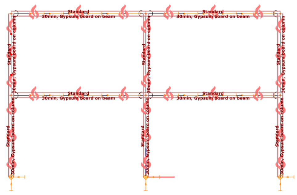
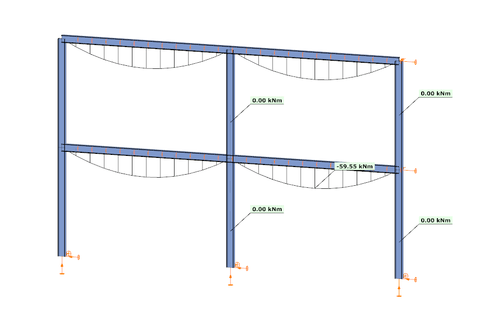
In the first case, the analysis is performed at room temperature. The beams develop a bending moment of approximately –59.55 kNm, while the columns carry primarily axial forces and show no significant bending moment along their length. This is consistent with the expected behavior based on the initial stiffness distribution of the structure.
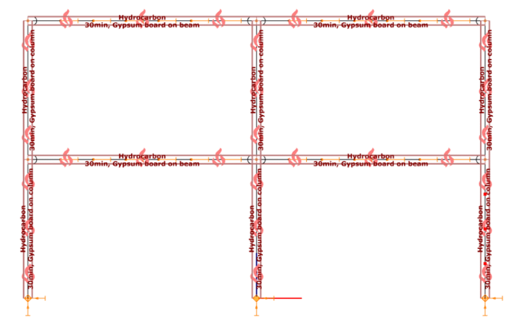
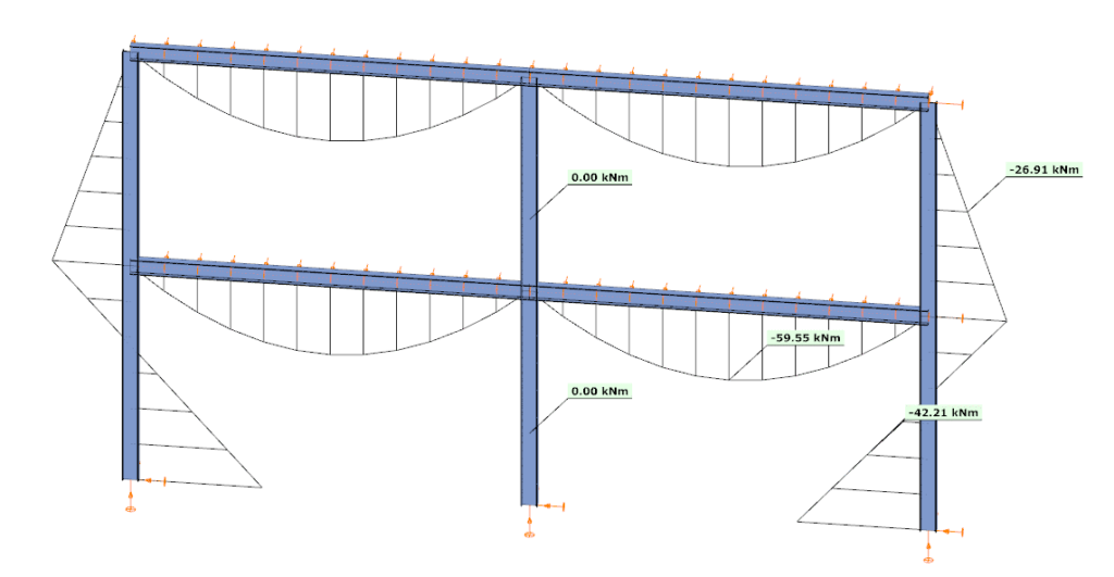
In the second case, the analysis is performed at elevated temperature, where reduced stiffness and thermal expansion are taken into account. The beam moment remains –59.99 kNm, but the internal force distribution in the structure changes. Bending moments appear in the columns, reaching approximately –26.91 kNm and –42.21 kNm at midspan.
This difference is a direct consequence of two coupled effects. First, the reduction in modulus of elasticity decreases the stiffness of heated members, modifying the relative stiffness distribution within the frame. Second, thermal expansion introduces additional deformations, which are partially restrained by the structural system. In statically indeterminate structures, such restraint generates additional internal forces, leading to redistribution of moments and the appearance of bending in members that were previously dominated by axial force.
From an engineering perspective, this comparison highlights that the internal force system under fire conditions is not a simple scaled version of the ambient-temperature state. Instead, it is the result of a different equilibrium condition, influenced by temperature-dependent material behavior and compatibility effects.
By allowing both types of analysis within the same model, Consteel provides a consistent framework to evaluate these phenomena. This supports more accurate assessment of structural performance in fire and enables informed decisions regarding fire protection and member design.
Download the example model and try it!
Download modelsIf you haven’t tried Consteel yet, request a trial for free!
Try Consteel for freeDid you know that you could use Consteel to calculate the elastic critical moment of a member subject to arbitrary loading and boundary conditions?
Calculating the elastic critical moment can quickly become difficult when beams have tapering, unusual restraints, or complex loads. Consteel simplifies the process and gives a quick, accurate result for any situation.
The elastic critical moment for lateral-torsional buckling is the theoretical bending moment at which a beam, free to sway sideways and twist, becomes unstable and buckles elastically, before yielding, representing the absolute upper limit of elastic stability for beam bending. It depends on: cross-section stiffness properties (Iz, Iw), material (E, G), span / buckling length, restraint to lateral displacement and to warping at the restraints, and on the shape of the moment diagram (via factors C1, C2, C3).
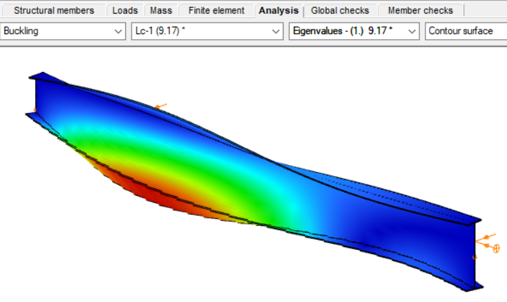
For doubly symmetric I- or H-sections with constant cross-section, uniform bending, and classical boundary conditions, the elastic critical moment Mcr can be calculated using the analytical formula:
However, for arbitrary support conditions and loading scenarios, the calculation becomes significantly more complex, and the classical formula is no longer applicable. In such cases, specialized software such as LTBeam or Consteel is required.
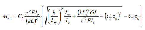
Let’s consider a tapered, welded I-section with pinned supports at both ends and two intermediate restraints, one at the bottom flange and one at the top flange. In addition to the uniform distributed load, a bending moment is applied at one end of the beam.
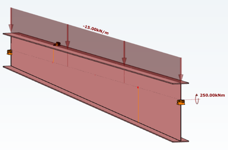
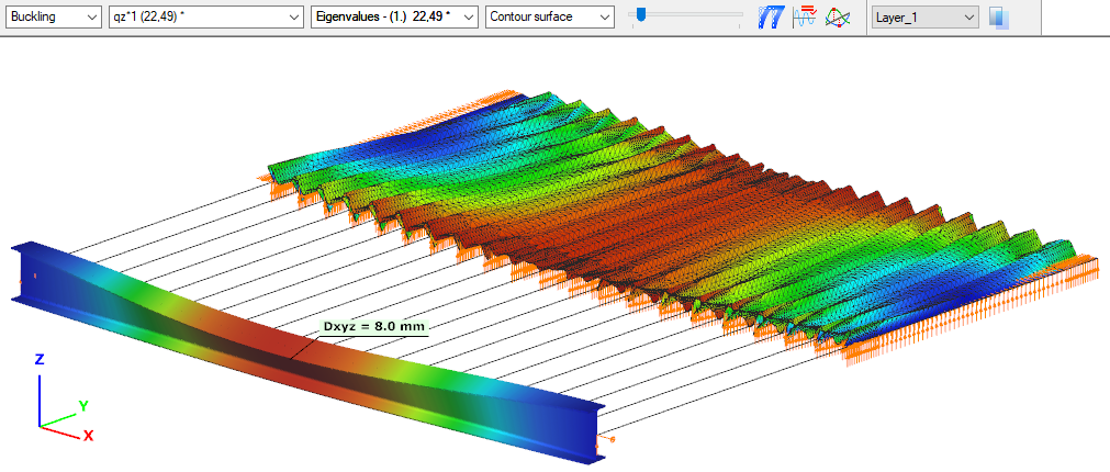
By performing a buckling analysis in the Analysis tab, the buckling shapes and the critical load factor (αcr) can be obtained. The elastic critical bending moment of the beam can be then calculated by multiplying the critical load factor by the maximum bending moment.
Consteel uses seven-degree-of-freedom finite element that fully accounts for tapering effects, torsion, and warping, key components in accurately capturing the true 3D behaviour of steel members. The seventh degree of freedom represents cross-sectional warping, which becomes visible in the buckling shape as the flanges move out of the plane of the cross-section.
Download the example model and try it!
Download modelIf you haven’t tried Consteel yet, request a trial for free!
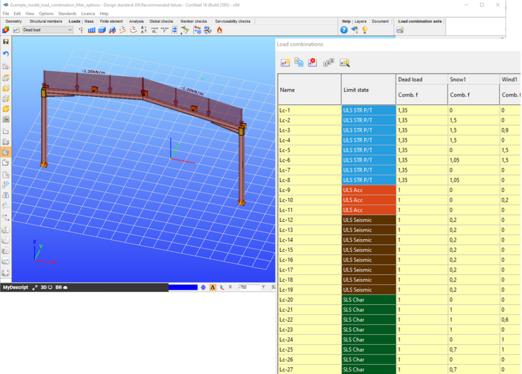
Try Consteel for freeConsteel offers a range of load combination filtering options, which can be applied based on limit states, load cases, and analysis and design results. By applying different series of filters, designers can streamline their workflow and reduce calculation time.
Filtering options
Filtering is realized through the Load combination set definition window.
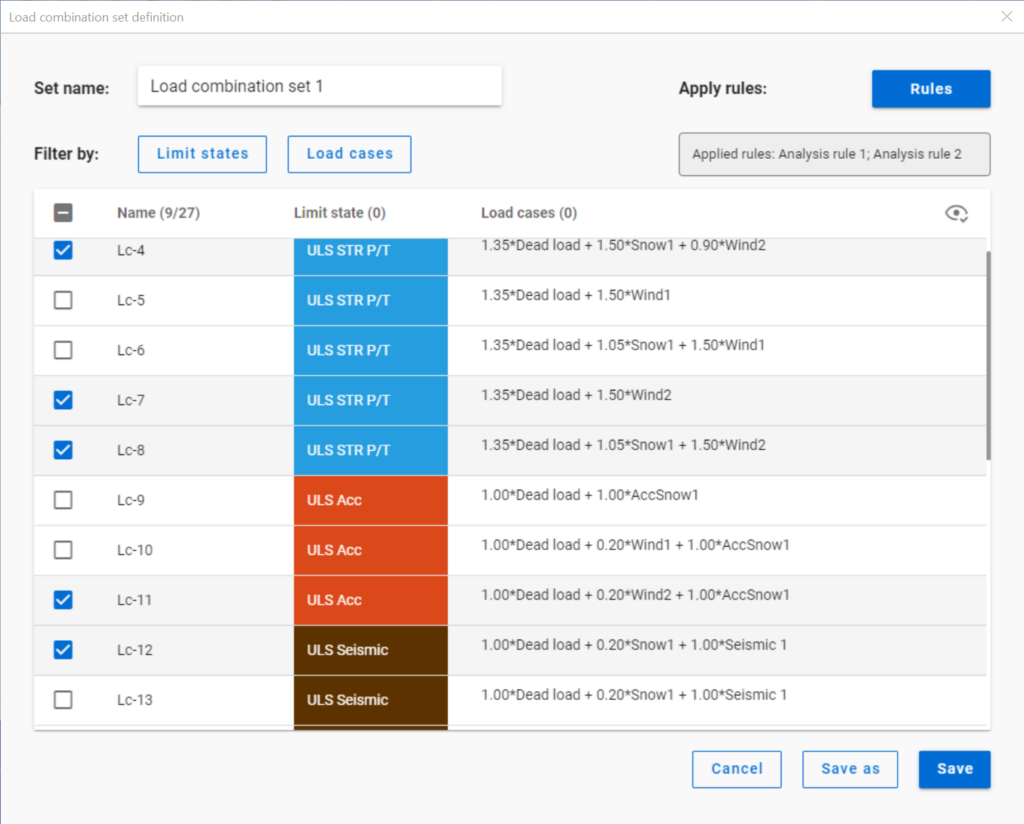
Filtering by limit states and by load cases are handled together with the checkboxes under the Limit states and Load cases buttons.
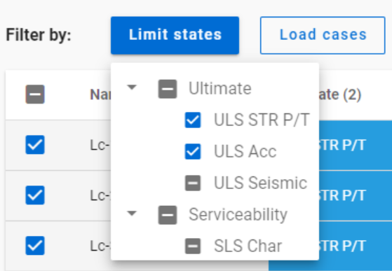
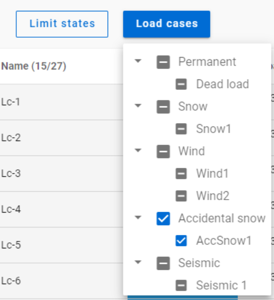
The 3-state checkboxes affect each other as they are not only used for selection but also for indication of the content. They can be manually set only to checked or unchecked. The middle state only appears when other filters are applied.
Filtering by limit states or load cases does not require any calculation results.
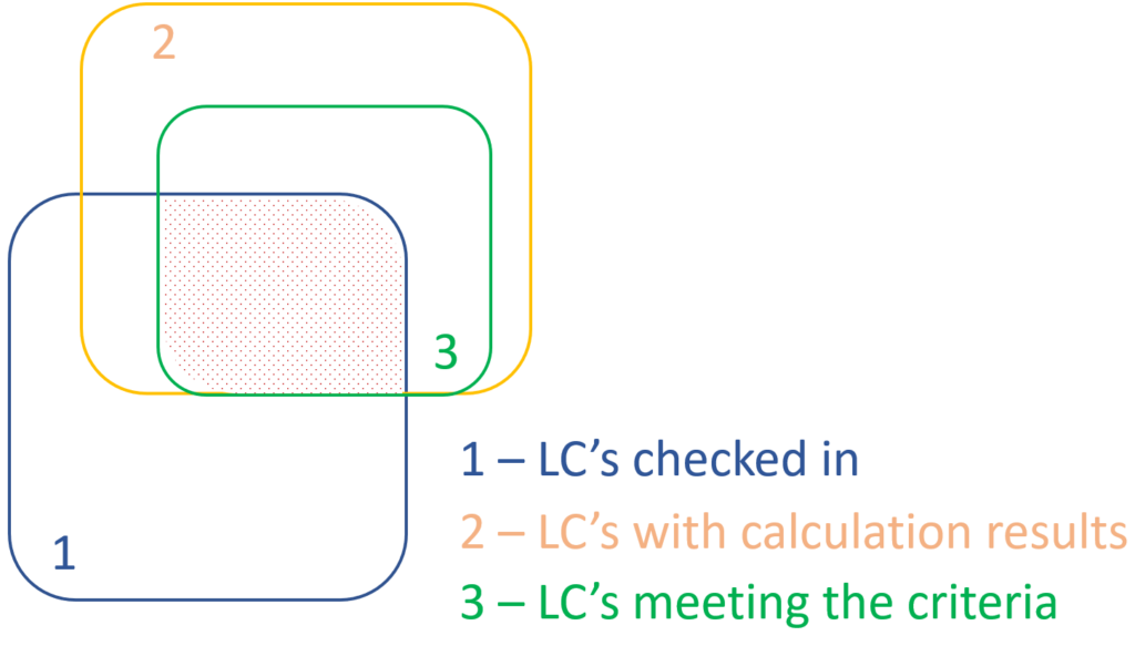
Filter by rules, on the other hand,is based on the actual analysis and/or design results. Different types of rules can be applied one by one or at the same time to select the desired load combinations.
When a rule is applied, all the load combinations that are selected on the Load combination set definition dialog- either with filtering by limit states/load cases or checked in manually- are examined at every position the rule indicates. Load combinations that meet the rule’s criteria are selected (remain checked in), while those that do not, become unchecked.
- With analysis rules, load combinations can be selected based on deformations or internal forces at either every finite element node or only at the member ends. This last one is included specifically for connection design. Deformations are checked in SLS combinations, internal forces are checked in ULS combinations only.
- With buckling rules, those ULS load combinations can be selected which have the elastic critical load factor (first buckling eigenvalue) less than the given limit.
- With design rules, load combinations can be selected based on utility ratios checked in every finite element node of the chosen portion. Utilizations are available from several design checks: dominant results and detailed verifications for steel elements such as general elastic cross-section check, pure resistances, interactions and global stability. Only ULS combinations can be filtered with design rules.
Interaction of the different filter types
Filtering by limit states, load cases, and rules can be used together, with rules being applied only to load combinations that are checked in and have the necessary calculation results.
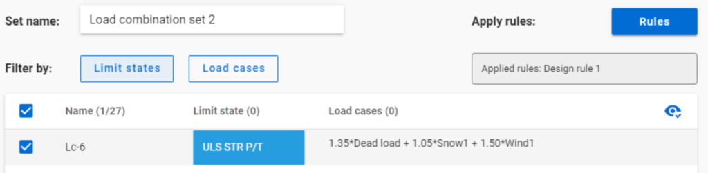
Let’s see an example.
It is a simple 2D frame model, with 27 load combinations of various limit states generated. Analysis and design results are calculated for all load combinations.
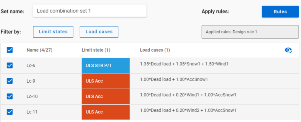
If applying design rule to select only those load combinations which result dominant utilization over 50%,
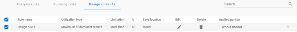
4 load combinations will be selected (Load combination set 1):
But if ULS Accidental limit state is turned off before applying the same 50% filter,
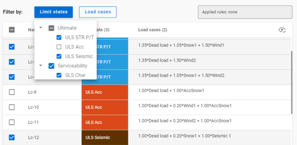
only one load combination is selected (see Load combination set 2).
Application of multiple rules
Applying multiple rules together results in the sum of the lists that would have been created separately.
gateIntroduction
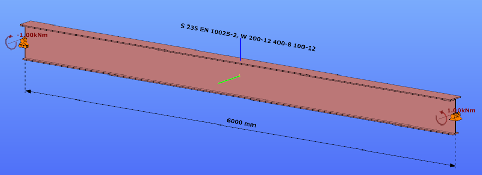
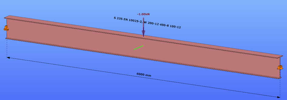
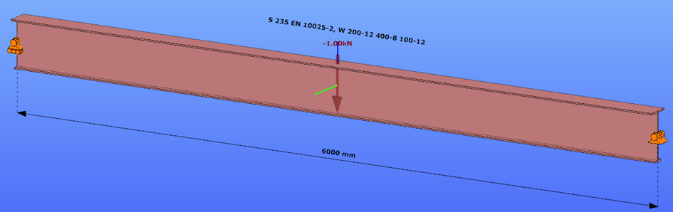
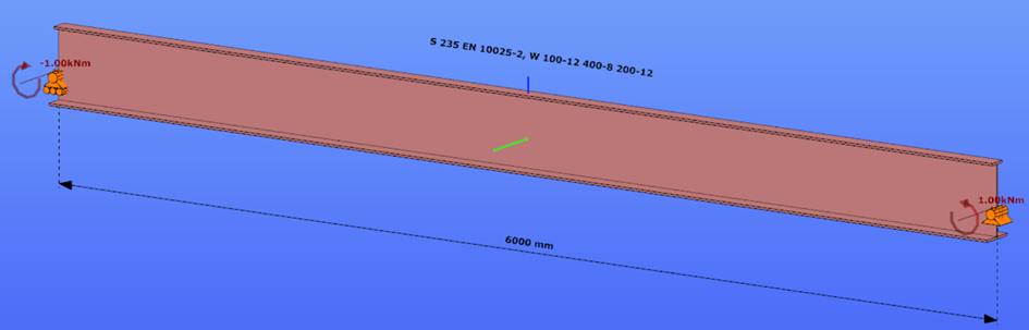
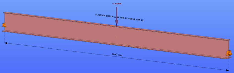
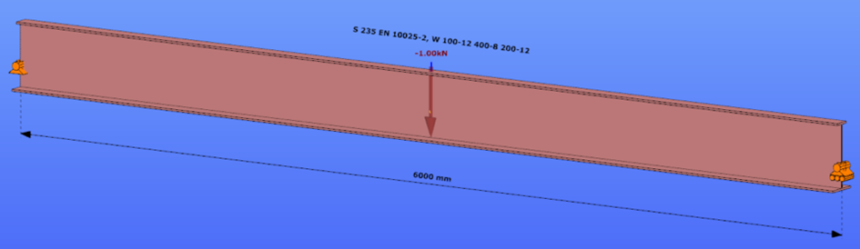
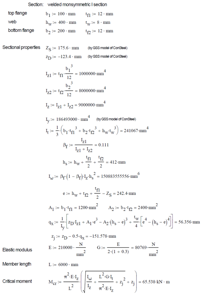
This verification example studies a simple fork supported beam member with welded section (flanges: 200-12 and 100-12; web: 400-8) subjected to bending about major axis. Constant bending moment due to concentrated end moments and triangular moment distribution from concentrated transverse force is examined for both orientations of the I-section. Critical moment and force of the member is calculated by hand and by the Consteel software using both 7 DOF beam finite element model and Superbeam function.
Geometry
Normal orientation – wide flange in compression
Constant bending moment distribution
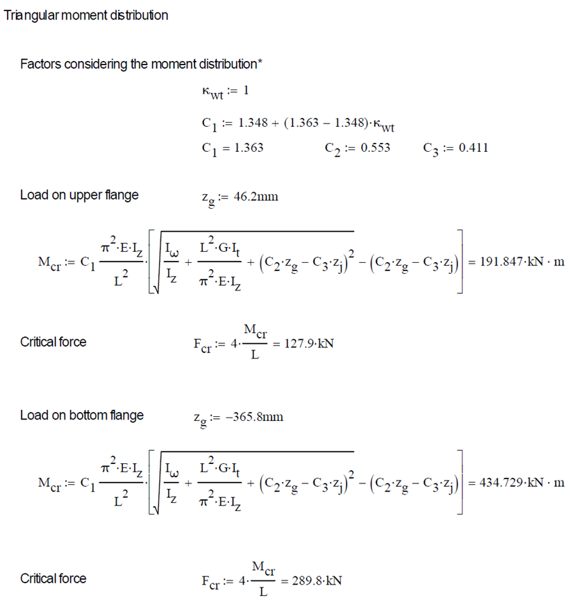
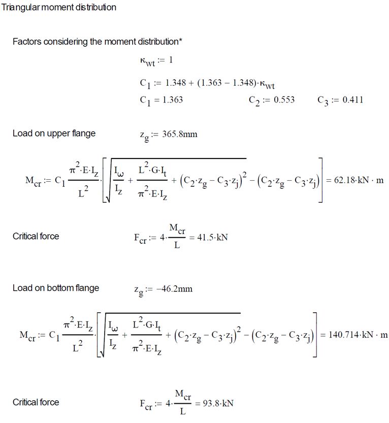
Triangular bending moment distribution – load on upper flange
Triangular bending moment distribution – load on bottom flange
Reverse orientation – narrow flange in compression
Constant bending moment distribution
Triangular bending moment distribution – load on upper flange
Triangular bending moment distribution – load on bottom flange
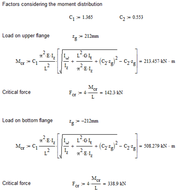
Calculation by hand
Factors to be used for analitical approximation formulae of elastic critical moment are taken from G. Sedlacek, J. Naumes: Excerpt from the Background Document to EN 1993-1-1 Flexural buckling and lateral buckling on a common basis: Stability assessments according to Eurocode 3 CEN / TC250 / SC3 / N1639E – rev2
Normal orientation – wide flange in compression
Constant bending moment distribution
Reverse orientation – narrow flange in compression
Computation by Consteel
Version nr: Consteel 15 build 1722
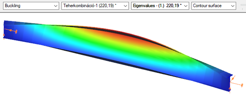
Normal orientation – wide flange in compression
Constant bending moment distribution
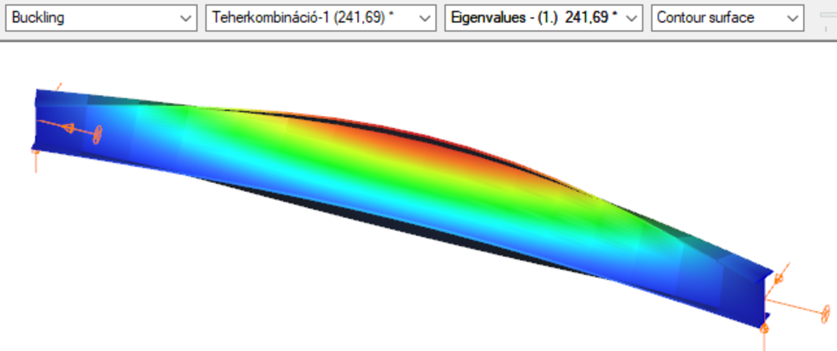
- 7 DOF beam element
First buckling eigenvalue of the member which was computed by the Consteel software using the 7 DOF beam finite element model (n=25). The eigenshape shows lateral torsional buckling.
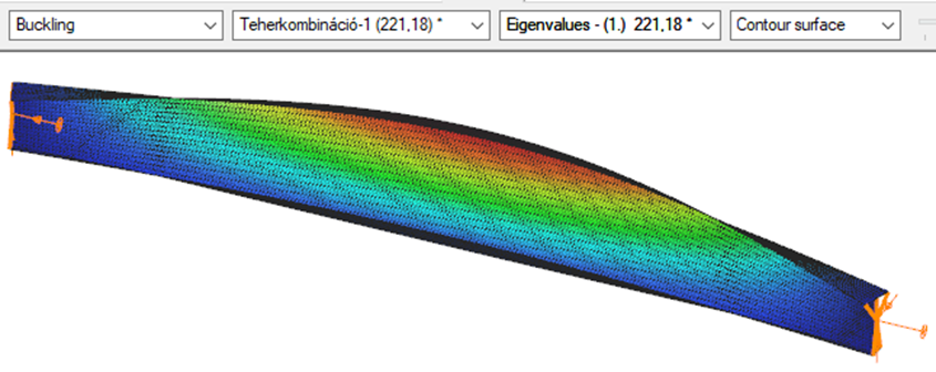
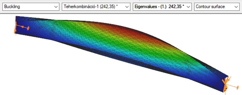
Superbeam
First buckling eigenvalue of the member which was computed by the Consteel software using the Superbeam function (δ=25).
Introduction
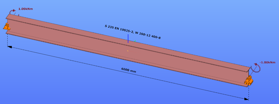
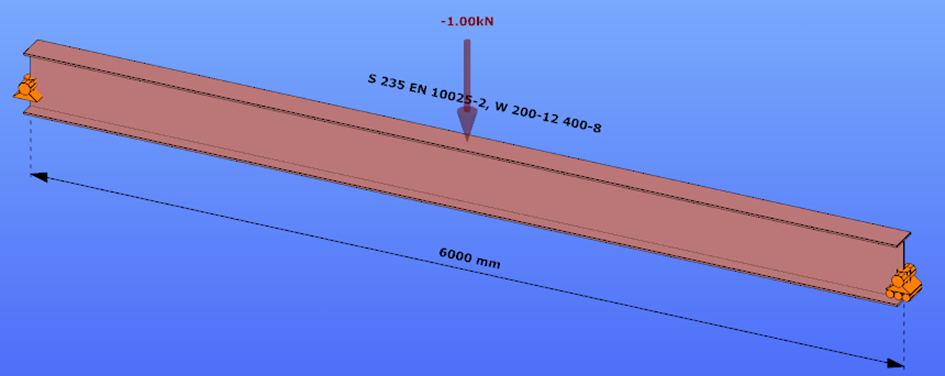
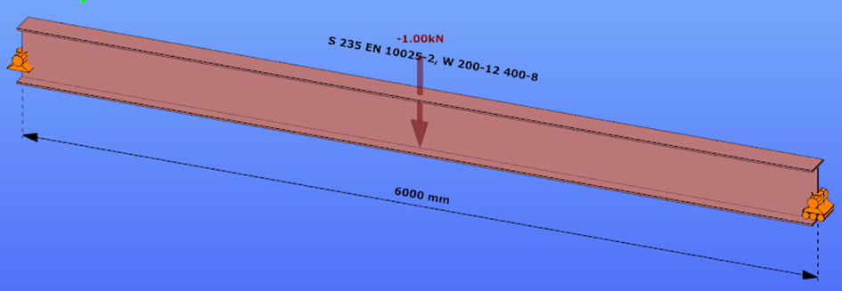
This verification example studies a simple fork supported beam member with welded section (flanges: 200-12; web: 400-8) subjected to bending about major axis. Constant bending moment due to concentrated end moments and triangular moment dsitribution from concentrated transverse force is examined. Critical moment and force of the member is calculated by hand and by the Consteel software using both 7 DOF beam finite element model and Superbeam function.
Geometry
Constant bending moment distribution
Triangular bending moment distribution – load on upper flange
Triangular bending moment distribution – load on bottom flange
Calculation by hand
Constant bending moment distribution

Triangular bending moment distribution
Computation by Consteel
Version nr: Consteel 15 build 1722
Constant bending moment distribution
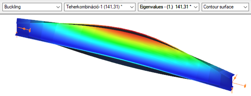
7 DOF beam element
First buckling eigenvalue of the member which was computed by the Consteel software using the 7 DOF beam finite element model (n=16). The eigenshape shows lateral torsional buckling.
Superbeam
First buckling eigenvalue of the member which was computed by the Consteel software using the Superbeam function (δ=25).
Triangular bending moment distribution – load on upper flange
7 DOF beam element
First buckling eigenvalue of the member which was computed by the Consteel software using the 7 DOF beam finite element model (n=16).
Superbeam
First buckling eigenvalue of the member which was computed by the Consteel software using the Superbeam function (δ=25).

Triangular bending moment distribution – load on bottom flange
(more…)