In Consteel, the calculation of cross sectional interaction resistance for Class 3 and 4 sections is executed with the modified Formula 6.2 of EN 1993-1-1 with the consideration of warping and altering signs of component resistances. Let’s see how…
Application of EN 1993-1-1 formula 6.2
For calculation of the resistance of a cross section subjected to combination of internal forces and bending moments, EN 1993-1-1 allows the usage -as a conservative approximation- a linear summation of the utilization ratios for each stress resultant, specified in formula 6.2.
$$\frac{N_{Ed}}{N_{Rd}}+\frac{M_{y,Ed}}{M_{y,Rd}}+\frac{M_{z,Ed}}{M_{z,Rd}}\leq 1$$
As Consteel uses the 7DOF finite element and so it is capable of calulcating bimoment, an extended form of the formula is used for interaction resistance calculation to consider the additional effect.
$$\frac{N_{Ed}}{N_{Rd}}+\frac{M_{y,Ed}}{M_{y,Rd}}+\frac{M_{z,Ed}}{M_{z,Rd}}+\frac{B_{Ed}}{B_{Rd}}\leq 1$$
Formula 6.2 ignores the fact that not every component results the highest stress at the same critical point of the cross-section.
In order to moderate this conservatism of the formula, Consteel applies a modified method for class 3 and 4 sections. Instead of calculating the maximal ratio for every force component using the minimal section moduli (W), Consteel finds the most critical point of the cross-section first (based on the sum of different normal stress components) and calculates the component ratios using the W values determined for this critical point. Summation is done with considering the sign of the stresses caused by the components corresponding to the sign of the dominant stress in the critical point.
(For class 1 and 2 sections, the complex plastic stress distribution cannot be determined by the software. The Formula 6.2 is used with the extension of bimoments to calculate interaction resistance, but no modification with altering signs is applied)
Example
Let’s see an example for better explanation.
GATEDid you know that you could use Consteel to build 3D models with smart link elements which automatically adapt the model when profiles are changed?
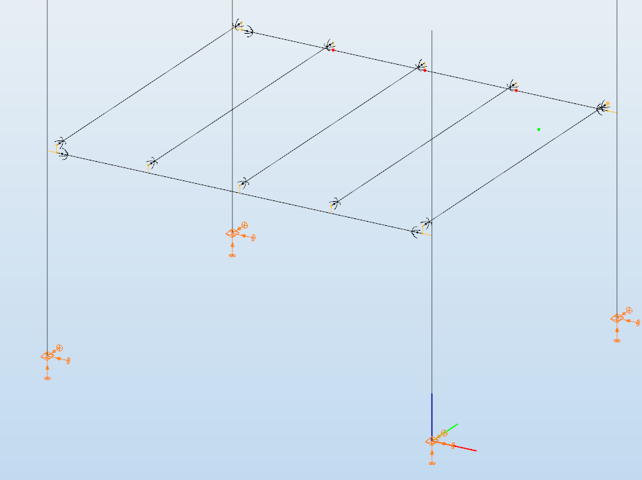
Link elements are used to connect members that are not directly joined. In Consteel, three types of link elements are available: Link, Smart Link, and Constraints.
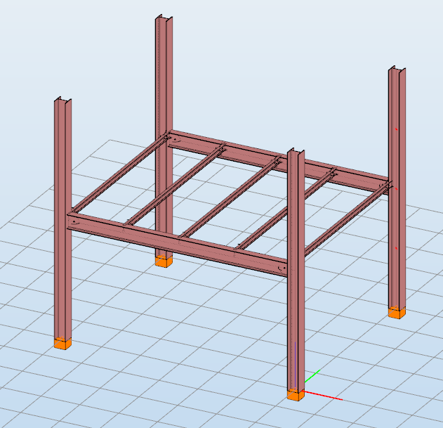
A smart link is a dynamic connection element designed to simplify the management of geometric changes between connected members. It automatically follows the movement, rotation, or profile changes of the primary member it is attached to, while also ensuring that any connected secondary member adapts accordingly.
A common application is connecting a main beam to a purlin or other secondary elements, with smart links positioned at specific points. They enable easy attachment of additional members while preserving the defined eccentricity, and automatically adapt to any changes in the main beam’s geometry or profile.
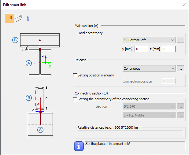
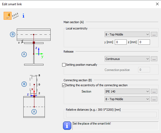
The Smart Link function, located on the Structural Members tab, opens the Edit Smart Link dialog box after activating the command. This allows you to:
- define the eccentricity of the link relative to the main section
- set the connection type in the Release field
The connection position can be specified manually or left to default automatically to the edge of the main member.
Defining the connecting section is optional. When specified, an eccentricity can be assigned, and the program automatically determines the link length based on the section height and reference point.
Smart links can be placed individually by clicking on a member or in groups by specifying distances from the member’s start. Any placement conflicts are indicated by a warning.
By combining associative behavior with precise control, Smart Links support efficient and reliable 3D modeling in Consteel. They help maintain structural intent throughout design changes, reduce manual corrections, and improve overall model consistency.
For workflows where geometry evolves and secondary members must remain accurately connected, Smart Links provide a clear advantage and enable a more resilient and adaptable modeling process.
Download the example model and try it!
Download modelIf you haven’t tried Consteel yet, request a trial for free!
Try Consteel for freeDid you know that you could use Consteel to determine the optimum number of shear connectors for composite beams?
In composite beam design, the required number of shear studs is not only a detailing issue but a direct part of the structural resistance mechanism. The modelling and design environment in Consteel allows this number to be determined in a rational and automated way, consistent with EN 1994-1-1:2010.
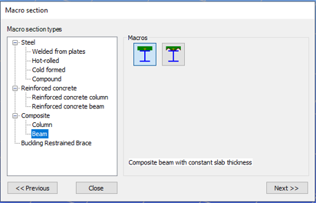
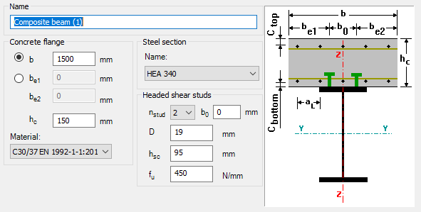
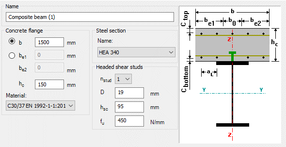
The process begins with the definition of a composite beam cross-section (Macro section). Two standard types are available: a solid slab composite beam and a profiled steel sheeting composite beam. The effective width is defined at input level, but the actual effective width used in analysis is calculated automatically based on span, geometry, and stud spacing assumptions. This ensures that the structural response is captured realistically, while maintaining simple input control for the user.
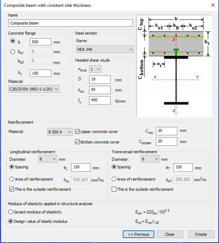
After defining the cross-section, the member is created and design parameters are assigned through object properties. These parameters govern key aspects of composite behaviour, including stud spacing, support conditions, and whether shear stud design is performed manually or automatically.
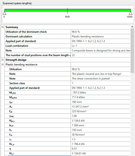
For shear connector design, Consteel applies a plastic distribution model. The governing section of the beam, typically corresponding to the maximum bending moment, is identified automatically. From this section, shear studs are distributed symmetrically along the beam length.
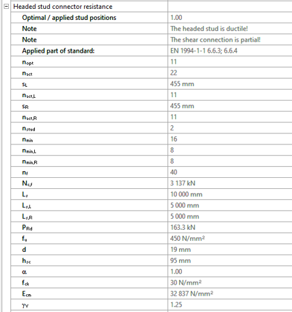
When automatic optimisation is selected, the software determines the minimum number of shear studs required to satisfy bending resistance. It then increases the number iteratively until the composite section achieves sufficient capacity. The resulting value represents the optimal number of shear connector positions for the given loading and geometry.

The key parameters used in this evaluation include:
- nopt: optimal number of shear stud positions in the governing region
- nact: actual number of stud positions applied
- sL, sR: spacing of studs on the left and right side of the critical section
- nmin: minimum required number of stud positions based on resistance
The ratio nact / nopt is used as a direct measure of utilisation of the shear connector system.
There is also the option to define the number of studs manually. In that case, Consteel distributes them uniformly along the member and checks compliance with detailing rules such as minimum and maximum spacing. This is typically useful when construction constraints or predefined detailing standards take priority.
Composite beam design itself is carried out according to EN 1994-1-1:2010. Plastic bending resistance is evaluated for Class 1 and 2 cross-sections, while shear, concrete flange crushing, and longitudinal shear are checked at critical sections. Shear buckling is treated according to EN 1993-1-5. Lateral-torsional buckling is not included in the current design scope.
For profiled sheeting, shear stud resistance is reduced depending on rib orientation, in line with Eurocode 4 rules.
Overall, the key point is that the number of shear connectors is no longer an assumed input. It is derived from structural demand through an automated and transparent process, which makes it easier to reach an efficient and consistent composite design without repeated manual iteration.
Download the example model and try it!
Download modelIf you haven’t tried Consteel yet, request a trial for free!
Try Consteel for freeDid you know that you could use Consteel to perform local and distortional buckling checks for cold-formed members?
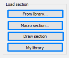
First, sections must be loaded into the model. To load cold-formed sections, you can choose from four options: From library, Macro section, Draw section, or My library.
After the first-order and buckling analyses are completed, you can proceed to the Ultimate limit state check settings and enable the steel design cross-section and buckling checks. At the bottom of the steel design section, there is an option to Consider the supplementary rules from EN 1993-1-3 for the design of cold-formed sections. This checkbox must be selected if you want to design cold-formed sections.
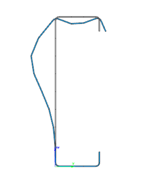
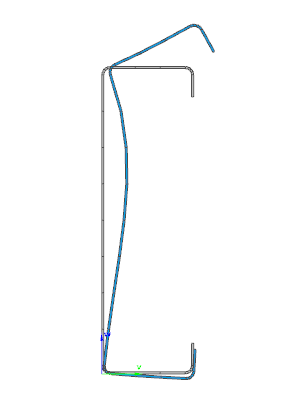
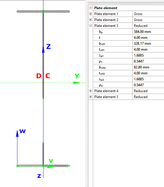
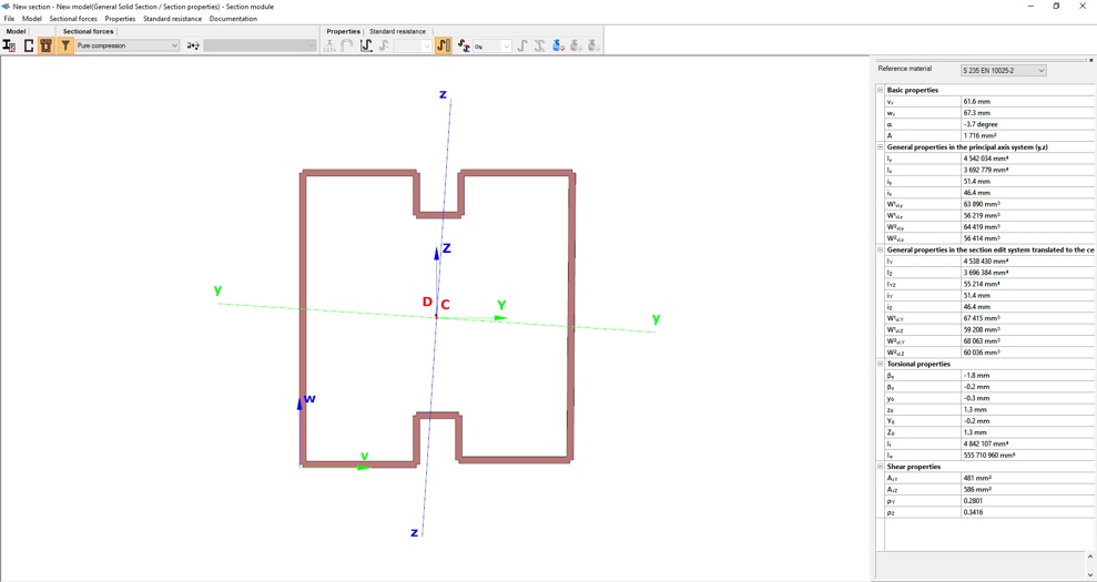
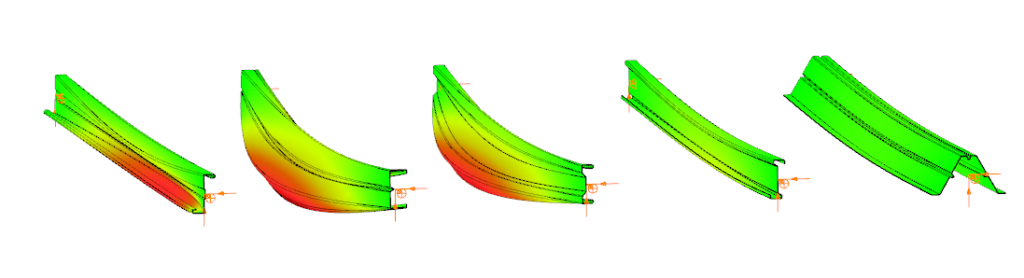
When the calculation is finished, by opening the Section module, we can review all the properties of the Effective section of the elastic plate segment model. By opening each plate element, we can verify the length, effective length, thickness, effective thickness, slenderness, and reduction factor separately. In addition, the properties of the stiffeners can also be verified: area, moment of inertia, lateral spring stiffness, critical stress, reduction factor, compressive stress, reduced effective area, and reduced thickness.
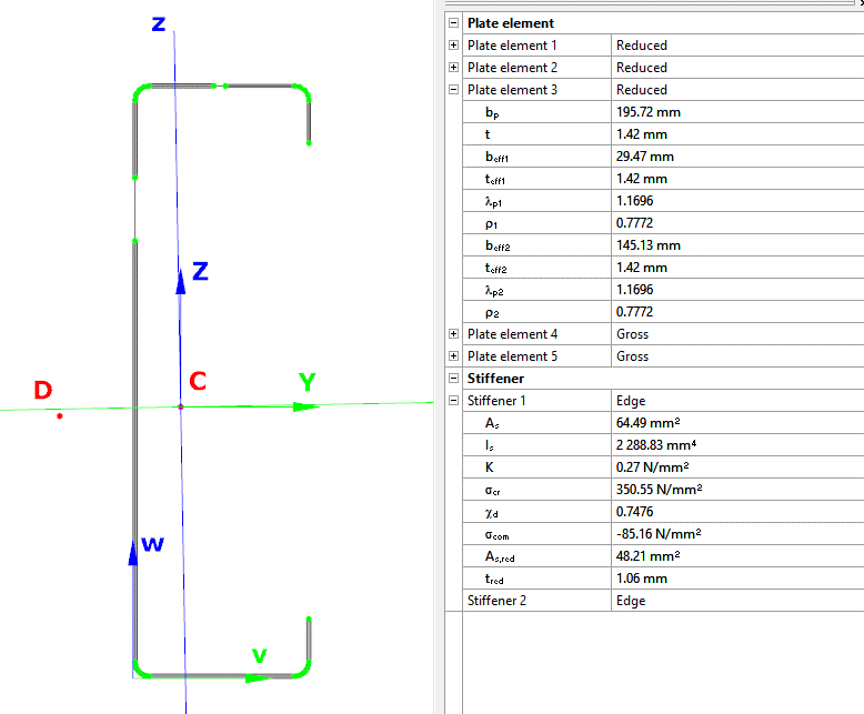
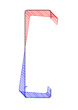
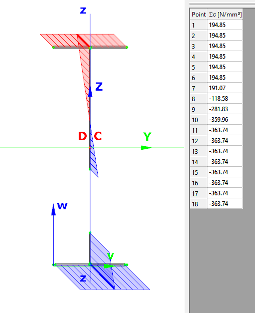
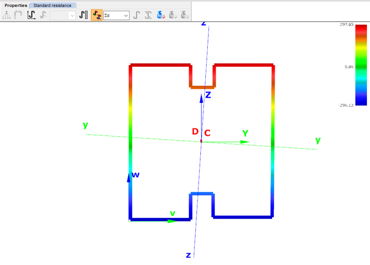
Similarly, the stresses can also be checked from the Properties tab. In the colored figure or diagram view, all the calculated stresses can be seen together with their resultants.
Consteel automatically takes into account the effect of distortional buckling when calculating the effective sections of cold-formed thin-walled sections.
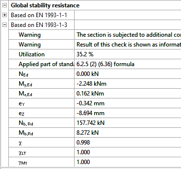
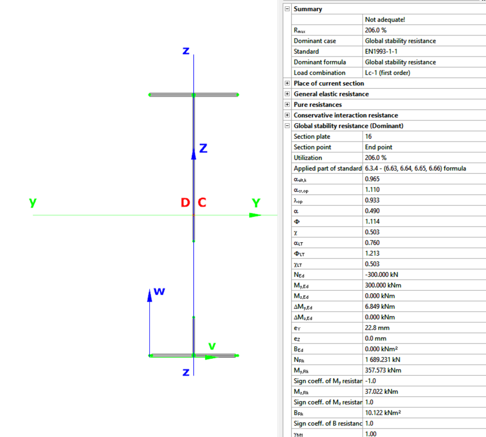
Moving on to the Standard resistance tab in the Section module, all calculated results can be verified, not only the dominant one. By opening the Global stability resistance check, we can see that, since we enabled the option to consider the supplementary rules from EN 1993-1-3 for the design of cold-formed sections, results are available both according to EN 1993-1-1 and according to EN 1993-1-3.
Download the example model and try it!
Download modelIf you haven’t tried Consteel yet, request a trial for free!
Try Consteel for freeDid you know that you could use Consteel to calculate effective cross-section properties for Class 4 sections?
The classification of cross-sections is used to understand how local buckling affects the strength and rotation capacity of structural members. As stated in Eurocode 3 (EN 1993-3-3, Section 5.5), this classification helps determine whether a cross-section can reach its full resistance or if its behavior is limited by local instability.
Class 4 cross-sections are those in which local buckling occurs before the material reaches the yield stress in one or more parts. Because of this, their resistance must be calculated using effective section properties that take into account the reduction caused by local buckling.
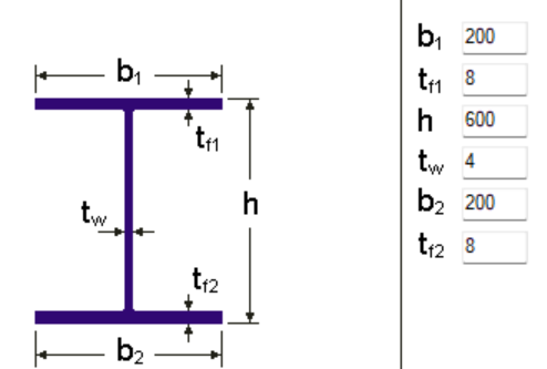
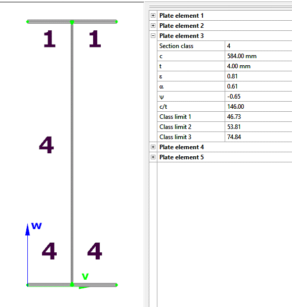
Typical Class 4 sections are characterized by slender elements with high width-to-thickness ratios. These commonly include thin webs or flanges, hollow sections (RHS/CHS) with slender walls, thin-walled cold-formed profiles such as C- or L-sections, and welded I-sections with slender webs. In this example, we consider a welded I-section with the following geometric parameters:
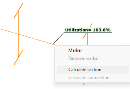
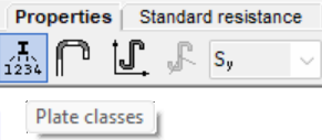
In Consteel, we can then see the section classification from the Global Checks tab. After selecting the investigated section either in the model or from the table and clicking on the Calculate Section option, and then choosing the Plate Classes in the Properties tab.
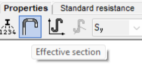
The effective section properties can then be viewed using the second option in the Properties tab.
In addition, stresses can be visualized by clicking on the Stresses icon. They can be represented either as a colored figure or as a 3D diagram.
For Class 4 sections, the Standard Resistance tab in the section module provides a complete assessment for the selected loading case.
The section module performs all necessary calculations according to the Eurocode (EN 1993-1-1 and relevant parts of EN 1993-1-5), including general elastic resistance, pure case resistance, conservative interaction checks, and web buckling analysis.
All resistances are calculated using the effective section properties to account for local buckling, and the module identifies the dominant case to ensure all relevant checks are covered.
Download the example model and try it!
Download modelIf you haven’t tried Consteel yet, request a trial for free!
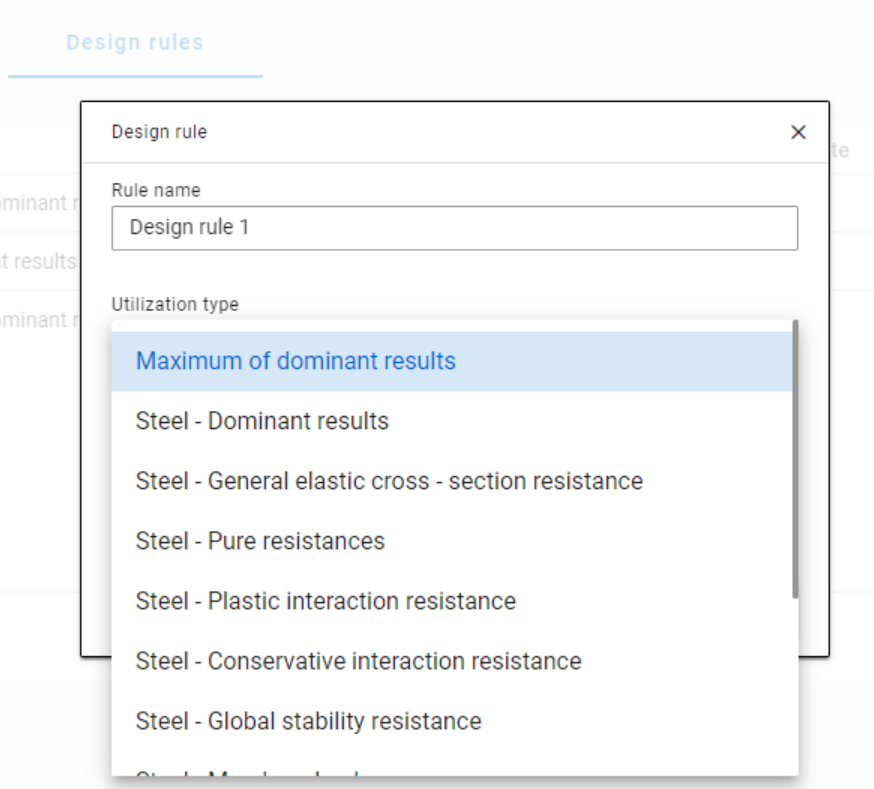
Try Consteel for freeWhen applying design rules in load combination filter, the most frequently used utilization type is Steel – Dominant results. What results are exactly considered by this option and what do corresponding limitations mean?
Introduction
There are four ways to apply load combination filter: based on limit states and load cases, manually, and by rules. Unlike the other three methods, filter by rules is only possible based on analysis and/or design results.
The most effective way to reduce the number of load combinations is definitely the use of design rules.
With design rules, load combinations can be selected based on utility ratios. Utilizations are available from several design checks, including dominant results and detailed verifications for steel elements, such as general elastic cross-section check, pure resistances, interactions, and global stability.
The meaning of the dominant check
The dominant check is not always the check which gives the maximal ratio but the one with the maximum RELEVANT ratio. Typical example: if plastic interaction formulas are valid, those results will be dominant over general elastic cross-section check results, although the latter are higher.
Steel – Dominant results
Steel – Dominant results option contains the utility ratio of the dominant check at every finite element node, in all load combinations. Meaning that there are as many utilization values as the number of load combinations calculated, in every FE node.
It is also important to understand the difference between the utilizations of Maximum of dominant results and Steel -Dominant results. Maximum of dominant results option contains the dominant utility ratio of the dominant load combination at every node, like an envelope of Steel-Dominant results. Meaning there is only one utilization value in every FE node. Also, it is the same as the dominant result table on Global checks tab.
When a rule is applied, the utilizations of the chosen utilization type are compared against the limitation. The load combinations which give the results that correspond to the limitation, are selected by the rule. Every FE node of the selected model portion is examined.
Limitations in case of Steel – Dominant results
- Maximum: to select the combinations which cause the maximum utilization at any node. It can be the same as Maximum of dominant results, except if there are combinations where the utilization is the same and it is maximal. In this case, here all the combinations are selected, while with Maximum of dominant results, there is always one maximum.
- More than % of maximum: to select the combinations as in ’Maximum’ plus those which cause utilization that is more than the given percentage of the maximum. E.g. at a certain point max utility ratio is 80%, Limitation= More than 90% of maximum. This rule will select all the load combinations which cause utility ratios between 0,9*80=72% and 80%.
- More than: to select the combinations which cause utilization more than the defined value at any point.
Let’s see an example of a simple 2D frame for better explanation. Right-side beam is in the portion for which three design rules were applied. Five points are selected for representation but of course all the nodes of the portion are examined against the rules’ limitations.
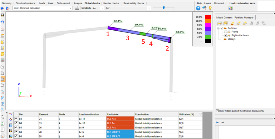
The utilizations of the five dedicated FE node in all 11 load combinations are shown on the below diagram. (To find all of these utilizations in the attached model, global checks must be calculated for the load combinations one-by-one.)
gateDid you know that you could use Consteel to Consider the shear stiffness of a steel deck as stabilization for steel members?
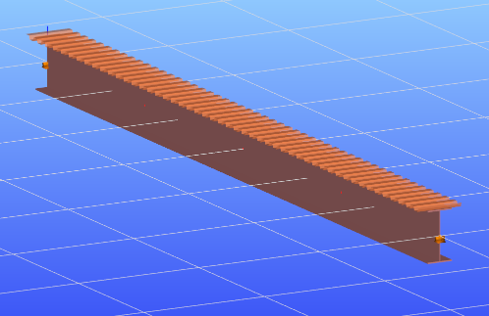
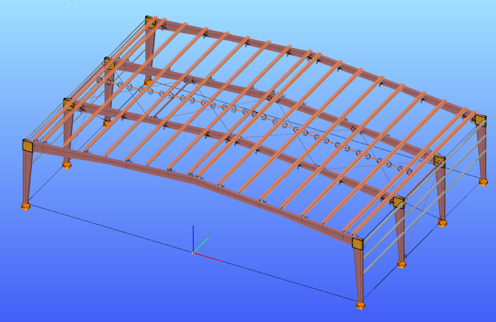
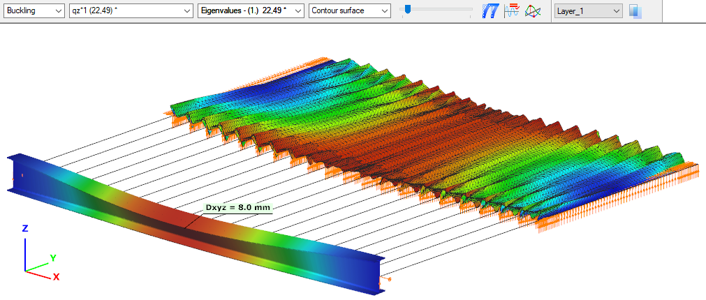
In many practical steel structures, trapezoidal decking is treated only as a load-bearing surface. In reality, when properly connected to the supporting members, it behaves as a shear diaphragm and contributes to the overall stability of the structure. This effect can be directly taken into account in Consteel by applying shear field stiffness to beam elements.

The stabilizing effect comes from the in-plane shear stiffness of the deck. Under horizontal loading, the sheeting deforms and transfers forces between structural members. This behavior can be described by a single parameter, the shear stiffness (S), which represents the resistance of the diaphragm against deformation.
The overall stiffness is influenced by several components, including the shear deformation of the sheet, profile geometry, fastener slip, and connection flexibility. These contributions together define how effectively the deck can restrain phenomena such as lateral-torsional buckling.
A key requirement for this behavior is proper fastening. Typically, the sheeting must be connected along its edges and fixed to supporting members at each rib to ensure reliable diaphragm action.
In engineering practice, shear stiffness is determined using standardized or manufacturer-based methods rather than detailed analytical models. Consteel supports several established approaches:
- Schardt/Strehl method (DIN 18807), based on parameters describing shear and warping deformation
- Improved Schardt/Strehl method, including the effect of fastener spacing
- Bryan/Davies method, considering additional structural parameters
- Eurocode-based method, using general geometric properties of the sheeting
These methods differ in complexity and required input data, but all aim to provide a realistic stiffness value for use in global analysis. If the sheeting is not fixed at every rib, the calculated stiffness must be reduced accordingly.
The shear field object in Consteel allows engineers to include the diaphragm effect without detailed shell modeling. The calculated shear stiffness can be assigned directly to beam elements, providing additional lateral restraint.
The process involves selecting a trapezoidal sheet profile, choosing the appropriate calculation method, and defining the relevant geometric and connection parameters. The software then determines the stiffness and incorporates it into the structural model.
Including shear stiffness in the analysis can lead to higher critical load factors and reduced displacements, resulting in more efficient structural designs. However, it also means that the decking becomes part of the stabilizing system.
Any later modifications to the sheeting, such as openings or changes in fastening, may reduce this effect and should therefore be carefully assessed.
The shear stiffness of trapezoidal steel decking provides a measurable and often significant contribution to structural stability. By incorporating this effect in Consteel, engineers can achieve more realistic analysis results and optimize their designs while maintaining structural safety.
Download the example model and try it!
Download modelIf you haven’t tried Consteel yet, request a trial for free!
Try Consteel for freeDid you know that you could use Consteel to draw a user-defined cross section and calculate its section properties?
In our previous article, we showed how predefined macro geometries make modelling fast and efficient. Later, we demonstrated how Consteel evaluates local and distortional buckling according to EN 1993-1-3.
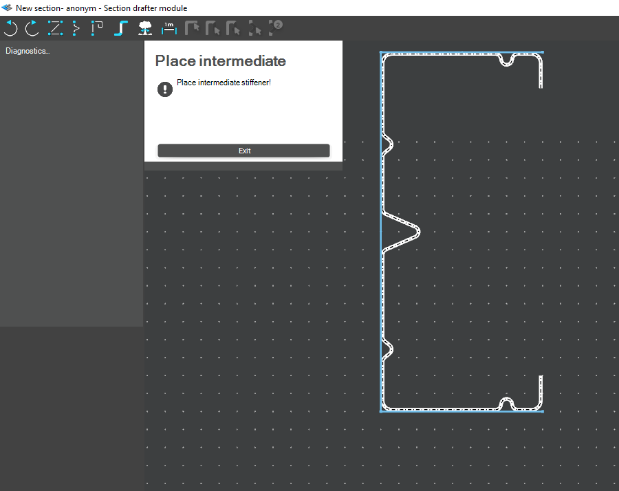
This article focuses on the most flexible solution within this workflow: creating your own cross-section from scratch using the Section drafter module.
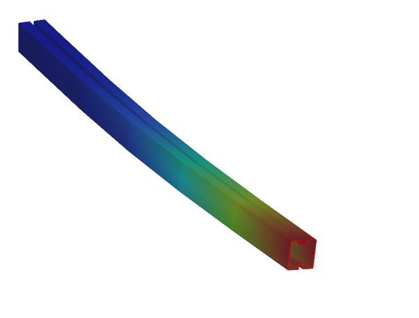
For line member modelling, the cross-section must first be loaded into the model. Besides using standard library profiles or macro sections, you can also choose the Draw Section option. This function is especially useful when a special geometry is required that cannot be reproduced with predefined macros, for example manufacturer-specific shapes, research sections, welded thin-walled members, or prototype geometries.
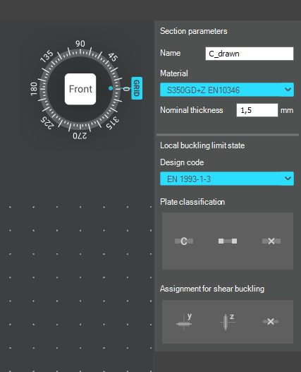
The Section drafter can be started from the Section Administration dialog by pressing the Draw section button. After launching the function, you need to select the section type, material quality and assign a name.
Two types of cross-sections are available: Cold formed section and General thin-walled section. This selection is not only geometric but also analytical.
Cold-formed sections are drawn with a single reference line and uniform thickness. During the calculation, Consteel automatically considers distortional buckling effects according to EN 1993-1-3. These sections can later be used in purlin line objects if they are defined as Z- or C-like shapes.
General thin-walled sections allow different thicknesses along the contour and closed geometries. They are typically used for welded or fabricated sheet sections. In this case, strength, local and global stability checks are available, but distortional buckling evaluation is not included.
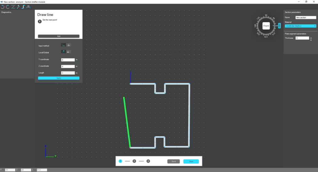
The drawing environment provides full control over geometry. Plate segments can be defined by coordinate input or by graphical selection. Cartesian or polar coordinates can be used, in local or global systems. Roundings are generated automatically between segments and can be modified later. The nominal thickness is also specified at this stage.
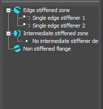
For cold-formed sections, stiffeners can be inserted using predefined macros, making it easier to model edge or intermediate stiffeners. However, these become structurally effective only after they are properly defined in the final phase of the section creation process.
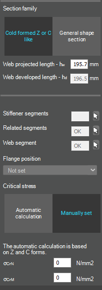
Once the geometry is complete, the required design parameters must be specified. For cold-formed sections, this includes the manufacturing type, thickness tolerance category and buckling curves. These inputs influence the calculated design wall thickness and stability verification. In the next step, the program evaluates the classification of each plate segment and determines the effective widths used in resistance calculations.
If stiffeners are present, they must be defined explicitly. When the section is identified as Z- or C-like, Consteel can automatically determine the critical stress of the stiffeners in accordance with EN 1993-1-3. This ensures that distortional buckling and stiffener interaction are properly considered during design.
After saving the section, it can be assigned to line members just like any library or macro profile. Following structural analysis, steel design checks can be performed. As shown in our article on buckling checks, the Section module allows detailed review of effective cross-sectional properties, reduction factors, slenderness values and stiffener behaviour. Consteel automatically accounts for distortional buckling when the supplementary rules of EN 1993-1-3 are enabled.
By combining library, macro, and user-defined sections, Consteel provides a complete workflow: fast modelling with macros, precise verification through buckling checks, and full flexibility with custom cross-sections.
Download the example model and try it!
Download modelIf you haven’t tried Consteel yet, request a trial for free!
Try Consteel for freeDid you know that you could use Consteel to include in your model a wide range of cold-formed macro sections?
For line member modelling, the cross-section must first be loaded into the model. In Consteel, there are four options to do this, either starting from the Section Administrator or directly during beam or column modelling: From Library, Macro Section, Draw Section, or My Library.
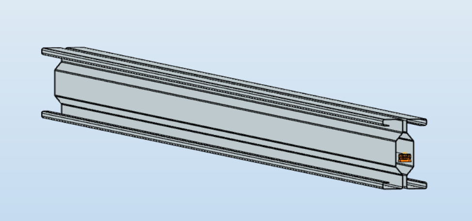
Cold-formed sections can be created using any of these four methods. Standard cold-formed cross-sections can simply be selected from the library. However, if a special cold-formed section is needed, it can be created via Macro Sections, including: RHS, CHS, L profile, Z shape, C shape, Sigma section, Zeta section, Hat section with stiffeners, double C section, double Sigma section, and double user-defined sections.
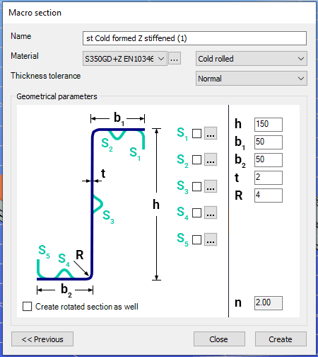
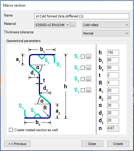
Macro sections are easy to create because the essential geometric characteristics are predefined, and the parameters can be modified intuitively. It is also possible to add profile stiffeners. Flange and web stiffeners can be configured in various forms, including single and double options. These defined stiffeners are included in the structural evaluation of distortional buckling, according to EN 1993-1-3.
The thickness tolerance category must be specified. This determines the design wall thickness for the section. In practice, macros follow the commonly applied tolerance categories used for coated steel sheet products.
If you want to use a double section, make sure to load into the model first the section that you want to duplicate.
For very special or unique sections, the Draw Section function can be used. This allows users to create fully custom cross-sections when standard or macro shapes are insufficient, by manually sketching the geometry.
Sections can be defined as cold-formed or general thin-walled, which determines how they are analyzed: cold-formed sections have uniform thickness and account for distortional buckling, while general thin-walled sections allow varied thicknesses and closed shapes, typically for welded or fabricated profiles.
This approach is especially useful for modelling unique shapes, prototypes, or as-built sections, giving full control over every segment to accurately capture geometries that standard libraries or macros cannot reproduce.
Download the example model and try it!
Download modelIf you haven’t tried Consteel yet, request a trial for free!
Try Consteel for freeDid you know that you could use Consteel to perform structural analysis at room and elevated temperatures as part of design process for fire resistance?
In structural fire engineering, the mechanical response of steel structures must be evaluated under both room and elevated temperature conditions. Consteel permits this by incorporating temperature-dependent material behavior directly into the finite element analysis, allowing engineers to assess not only resistance but also changes in global structural response.
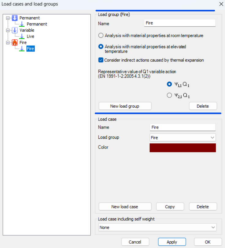
During fire analysis, Consteel determines the steel temperature and applies the corresponding reduction in material properties, most notably the modulus of elasticity and yield strength. These reductions are defined according to Eurocode 3 (EN 1993-1-2). As a result, the calculated internal forces and deformations reflect both the applied loads and the effects of thermal expansion and stiffness degradation. The analysis is performed on the global structural model, so compatibility effects and force redistribution are inherently captured.
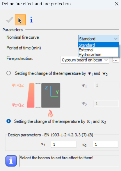
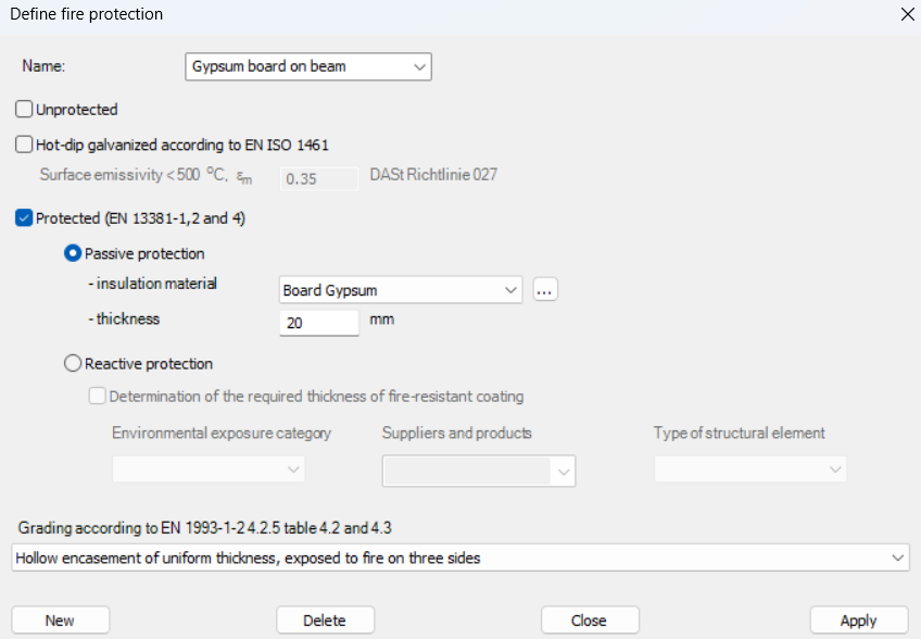
Fire exposure is defined using nominal fire curves (Standard, External, Hydrocarbon), together with a specified fire resistance time. In addition, the model allows assignment of fire protection conditions, including unprotected members, hot-dip galvanized surfaces, and protected elements with either passive insulation or reactive (intumescent) coatings. These definitions influence the temperature development in the structural members and, consequently, their mechanical response.
For design verification, Consteel applies the resistance models of EN 1993-1-2. Cross-section resistance is calculated using temperature reduction factors, depending on the type of internal force and cross-section class. Checks are performed for tension, compression, bending, and shear, as well as their interaction. For global stability, the software uses the Eurocode general method with modified buckling curves and reduction factors adapted for elevated temperatures.
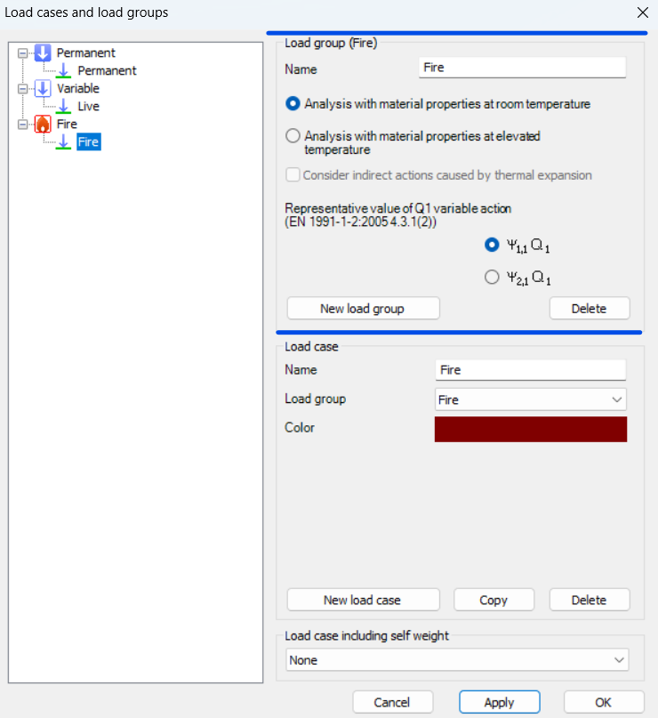
In addition to elevated-temperature analysis, Consteel supports a complementary approach based on room-temperature analysis for critical temperature determination. In this case, the structural analysis is carried out with ambient material properties, and the objective is to find the temperature at which the reduced resistance equals the internal forces from the governing load combination. This method is particularly relevant for members with intumescent coatings, where the coating performance depends on the critical steel temperature. The calculated critical temperature can then be used to determine the required coating thickness based on product-specific data.
The difference between these two approaches can be illustrated using a two-storey frame model.
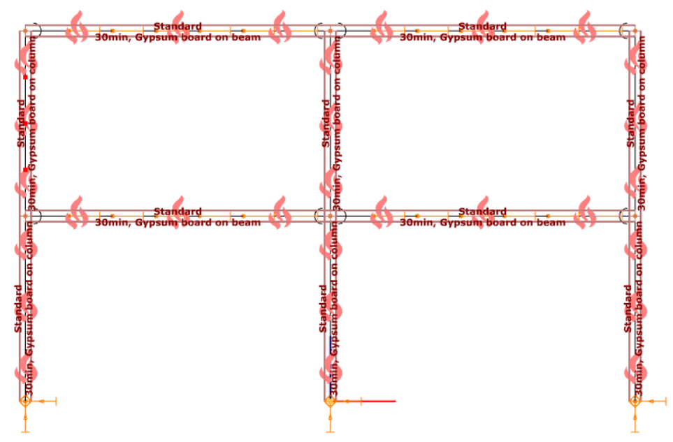
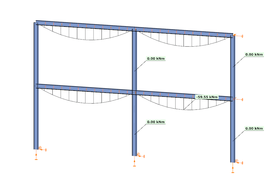
In the first case, the analysis is performed at room temperature. The beams develop a bending moment of approximately –59.55 kNm, while the columns carry primarily axial forces and show no significant bending moment along their length. This is consistent with the expected behavior based on the initial stiffness distribution of the structure.
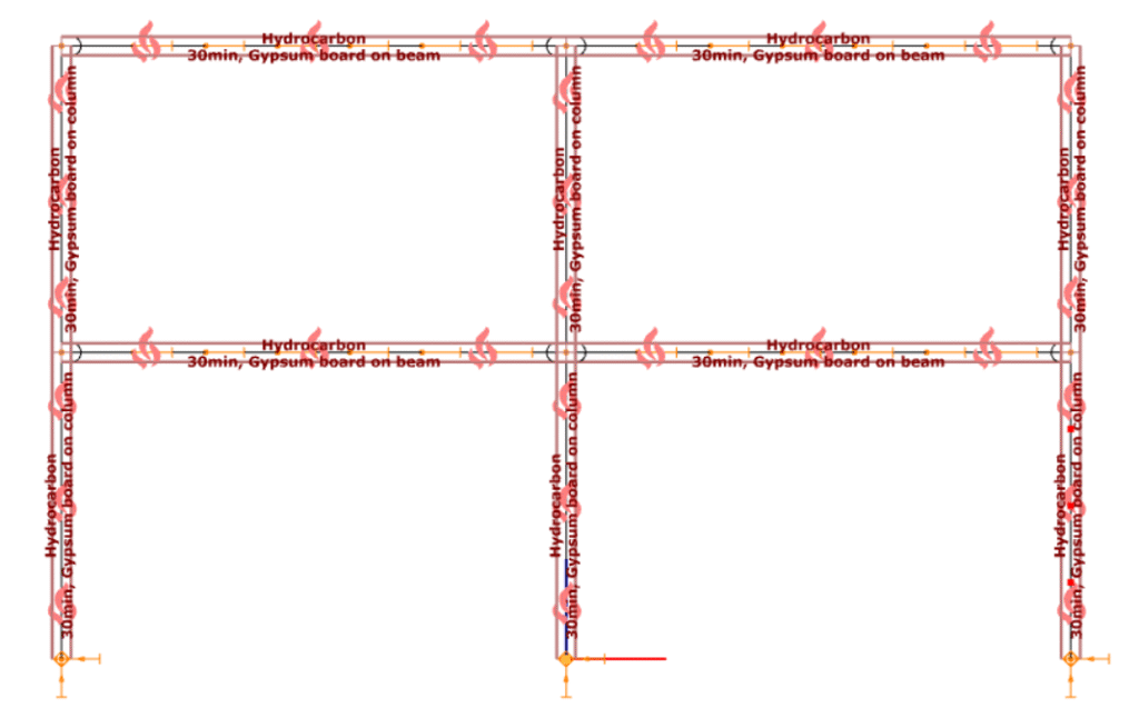
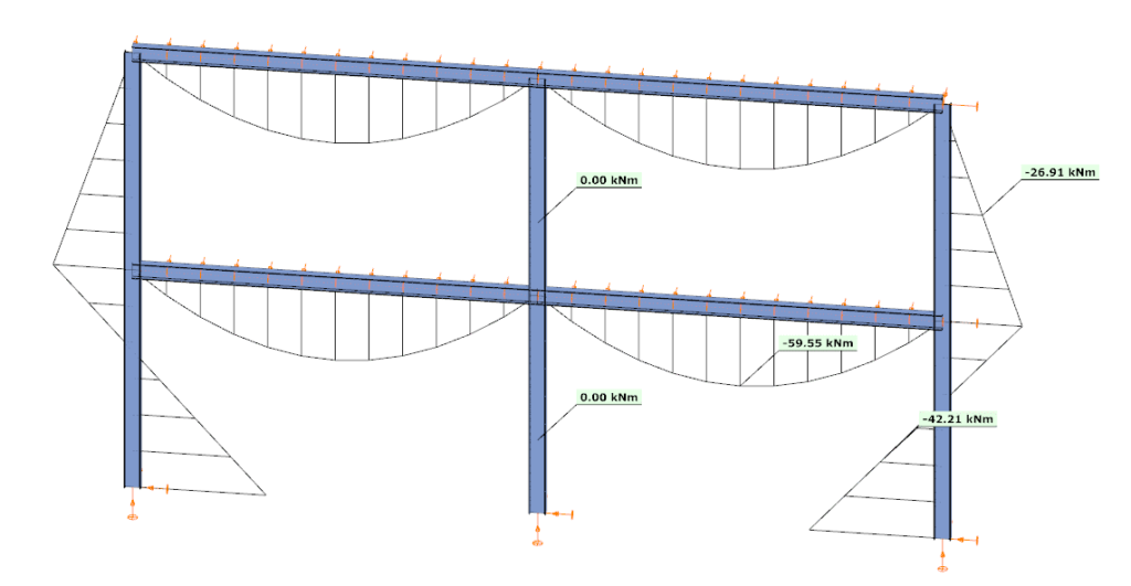
In the second case, the analysis is performed at elevated temperature, where reduced stiffness and thermal expansion are taken into account. The beam moment remains –59.99 kNm, but the internal force distribution in the structure changes. Bending moments appear in the columns, reaching approximately –26.91 kNm and –42.21 kNm at midspan.
This difference is a direct consequence of two coupled effects. First, the reduction in modulus of elasticity decreases the stiffness of heated members, modifying the relative stiffness distribution within the frame. Second, thermal expansion introduces additional deformations, which are partially restrained by the structural system. In statically indeterminate structures, such restraint generates additional internal forces, leading to redistribution of moments and the appearance of bending in members that were previously dominated by axial force.
From an engineering perspective, this comparison highlights that the internal force system under fire conditions is not a simple scaled version of the ambient-temperature state. Instead, it is the result of a different equilibrium condition, influenced by temperature-dependent material behavior and compatibility effects.
By allowing both types of analysis within the same model, Consteel provides a consistent framework to evaluate these phenomena. This supports more accurate assessment of structural performance in fire and enables informed decisions regarding fire protection and member design.
Download the example model and try it!
Download modelsIf you haven’t tried Consteel yet, request a trial for free!
Try Consteel for free