Wprowadzenie
Zbieranie i publikowanie naszych nowych rozwiązań zajmuje zazwyczaj około roku. Te nowości zazwyczaj zbiegały się w kolejnej nowej wersji Consteel, naszego flagowego produktu. Jednakże obecnie nowości obejmują znacznie szerszy zakres funkcjonalności aniżeli tylko nowe narzędzia w Consteel. W zeszłym roku opublikowaliśmy nową stronę internetową, która ma być centrum wielu usług dla klientów, włączając w to licencjonowanie, naukę, wsparcie, czy budowanie społeczności. Również uruchomiliśmy Steelspace, naszą platformę opartą o chmurę. Wszystkie te zmiany zostały stworzone aby wspomóc pełen zakres Państwa pracy i utrzymać głębsze relację między Państwem i nami. Chcemy być realną częścią Państwa pracy, prezentując szersze możliwości zwiększenia wydajności dzięki nowoczesnym technologiom. Jesteśmy głęboko przekonani, że powinni być Państwo świadomi naszych wizji, strategii i planowanych kierunków rozwoju, dlatego chcemy aby rozumieli Państwo nasze cele związane z nowościami. W dalszej części podzielimy się kilkoma wyszczególnionymi celami i kierunkami, oraz podsumujemy poczynione wysiłki aby podążać naprzód z naszymi nowymi funkcjonalnościami.
Służąc Państwa wydajności
Cel: udostępnić w jednym miejscu wszystkie dodatkowe usługi dla Państwa pracy
Wierzymy, że dzielenie się naszymi podstawowymi wartościami może znacznie pomóc w Państwa pracy. Dlatego zapewnimy miejsce w którym będą mieli Państwo łatwym dostęp do naszej uporządkowanej wiedzy i doświadczenia w analizie konstrukcji, do normowych metod wymiarowania i najnowszych nowoczesnych technologii branży budowlanej: to jest nasze nowe Centrum Usług. Będzie ono zawierać rozszerzoną wersję Podręcznika użytkownika w nowej formule online, z łatwą nawigacją między wątkami. W Bazie wiedzy zbieramy wszystkie materiały szkoleniowe i różnego rodzaju modele, aby pomóc Państwu zrozumieć w jaki sposób opracować efektywny przepływ pracy projektowej w Consteel. W Bibliotece skryptów udostępniamy kilka przygotowanych przykładów skryptów, gotowych do uruchomienia w Państwa programie Consteel, a pokazujących najlepsze praktyki korzystania z interfejsów skryptowych.

Bądź z nami na bieżąco
Cel: rozwijać i utrzymywać lepszą komunikację z Państwem
Chcemy ulepszyć połączenie i komunikację między Państwem i nami. Chcemy być pewni, że wszystkie istotne dla Państwa informacje dotrą na czas, niezależnie od tego, czy będą to treści w naszej nowej Bazie wiedzy, informacje o aktualizacji oprogramowania, czy też nadchodzące wydarzenia. Od teraz będzie możliwość informowania Państwa nie tylko przez newsletter, stronę internetową ale bezpośrednio w Consteel w nowym Otwartym oknie dialogowym. Będziemy tam udostępniać wszystkie newsy, Państwo natomiast zyskają możliwość szybkiego dostępu do naszej strony, Bazy wiedzy, czy bloga aby uzyskać więcej informacji. Natomiast, by nie niepokoić niechcianymi i nieciekawymi tematami, ale otrzymywać wyłącznie istotne i świeże informacje, kanał informacyjny będzie można spersonalizować.
Kontrola swojej licencji
Cel: dostarczyć w Państwa ręce przejrzysty i elastyczny system licencjonowania
Zauważamy, że różne firmy mają odmienne wymagania związane z licencjonowaniem – od licencji pojedynczych, przez grupowe, z kluczem sprzętowym, on-line, wieczyste, aż po czasowe. Dlatego stworzyliśmy elastyczny system licencjonowania pokrywający większość potrzeb i oddający kontrolę nad licencją w Państwa ręce. Zawsze można sprawdzić aktualny status i w prosty sposób zmienić ustawienia w Consteel lub na swoim osobistym koncie. na naszej stronie internetowej. Poprzez nowe narzędzie, przygotowane zostały dalsze opcje licencjonowania oparte głównie o okresowe subskrypcje. Można będzie wybrać najdogodniejszy typ licencji spośród szerokiej gamy opcji i ustawień.

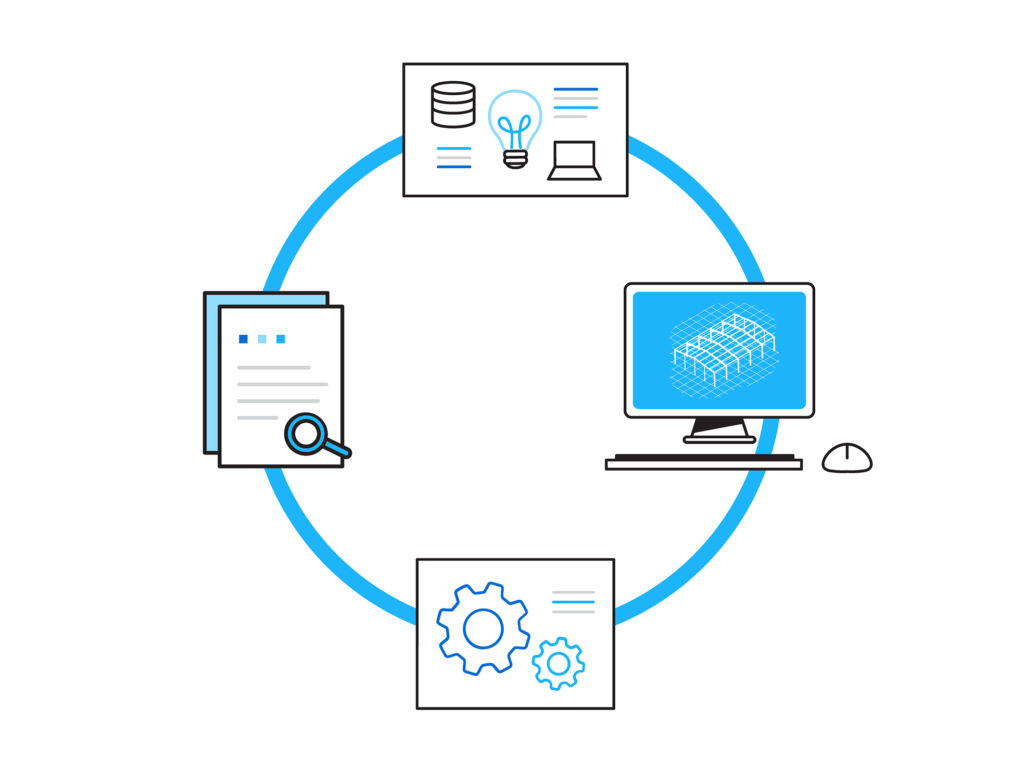
Tryb online
Cel: pozwolić Państwu korzystać z naszych dodatkowych usług w chmurze
Rozwiązania w chmurze mogą otworzyć nowy wymiar dla wielu usług. Dlatego chcemy aby przenieśli się Państwo również na zewnątrz swojego komputera. Jako pierwszy krok ułatwiamy zapisywanie i przechowywanie Państwa modeli i wyników w chmurze na osobistym koncie Steelspace. Dzięki nowym możliwościom cloud-save i cloud-open nie ma potrzeby nawet otwierać przeglądarki internetowej, używa się tej funkcji tak, jakby server w chmurze znajdował się na Państwa komputerze. Państwa modele są zapisane na serwerze w chmurze, i można je szybko przeglądać, oraz otworzyć bezpośrednio z Consteel. Steelspace, platforma usług w chmurze, umożliwia Państwa modelom opcje przechowywania, udostępniania i komentowania. Dodatkowo, wszystkie przyszłe usługi implementowane w Steelspace będą dla Państwa wygodnie dostępne.
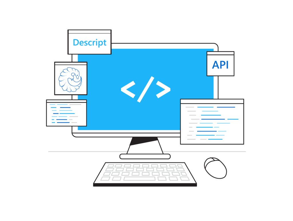
Łatwe tworzenie skryptów
Cel: promowanie i wspieranie tworzenia skryptów jako najbardziej postępowej możliwości efektywnego modelowania i dokonywania zmian
Tworzenie skryptów jest potężnym narzędziem w państwa rękach, które pozwala na tworzenie, dostęp i elastyczne operowania obiektami modelu, zmianami i obliczeniami na nich. Wiemy, że nie zawsze jest to łatwe lub znane projektantom konstrukcji, dlatego też chcemy przybliżyć Państwu moc skryptów. Interfejsy Programowania Consteel obejmują wielopoziomowe opcje skryptowania: wizualne skryptowanie wtyczką Pangolin w Grasshopper, wewnętrzne skryptowanie za pomocą naszego własnego środowiska Descript, oraz zewnętrzne skryptownie za pomocą naszego własnego środowiska API.NET. Wszystkie te opcje odpowiadają różnym poziomom umiejętności programistycznych i każdy znajdzie tę, która jest dla niego najodpowiedniejsza. Co więcej, nowe Centrum Usług zapewni Państwu Bibliotekę skryptów, z użytecznymi przykładami skryptów na wszystkich poziomach i do różnych celów. Łatwy dostęp i uruchamianie Państwa skryptów – z komputera albo z chmury – wspierane jest przez nowe środowisko MyScripts.

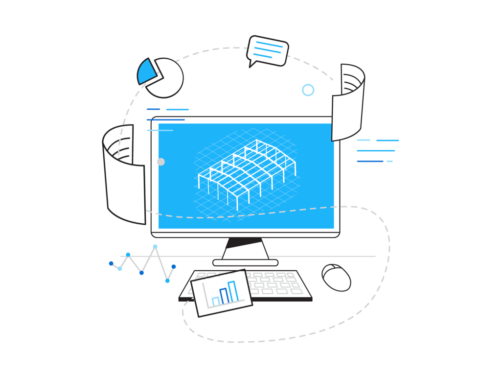
Informacyjna wizualizacja
Cel: zapewnienie środowiska graficznego z wysokim poziomem transferu informacji
Wizualizacja modelu i wyników jest kluczowa dla dobrego inżyniera. Wiadomym jest, że dobra wizualizacja pomaga i przyspiesza lepsze zrozumienie i poprawną interpretację jakichkolwiek danych modelu, w porównaniu z tekstem czy tabelami. Szybkie i poprawne rozumienie zdecydowanie prowadzi do bardziej efektywnej pracy. Dlatego też, chcemy wspierać Państwa efektywność, oferując przydatne nowe opcje wizualizacji modelu konstrukcji i wyników analizy. W fazie modelowania będą Państwo mieli możliwość przełączyć się na nowy widok modelu, w którym pręty otrzymują kolory w zależności od rodzaju ich przekroju. Wprowadziliśmy również kilka immersyjnych wizualizacji wyników w globalnym modelu, oraz na poziomie przekroju.

Superpręt
Cel: rewolucyjna reprezentacja elementów konstrukcyjnych z detalami modelu i podwójnymi opcjami analizy
Ponownie zrobiliśmy duży krok naprzód w kierunku modelowania i analizy stalowych elementów konstrukcyjnych. Stalowe belki i słupy są najczęściej używanymi obiektami modelu w procesie projektowania, chociaż mogą się one bardzo różnić pod względem kształtu, szczegółów, zachowania i związanych z nimi potrzeb analitycznych i wymiarowania. W naszej nowej koncepcji superpręta, można zachować łatwe i szybkie modelowanie tych elementów rozszerzone o kilka nowych adaptacyjnych funkcji detalowania (otwory, użebrowanie etc.), podczas gdy analiza może być wykonywana na dwóch spójnie generowanych modelach obliczeniowych. Prętowy model MES z dobrze znanymi możliwościami analitycznymi i wymiarowania zawiera obecnie kilka szczegółowych opcji zachowania się konstrukcji. Drugą opcją jest powłokowy model MES dla elementu spójnie połączony z globalnym modelem prętowym MES, zawierający dodatkowe otwory i żebra. Można łatwo przełączać się między opcjami analizy, ponieważ cały proces jest w pełni adaptacyjny. Modeluje się i modyfikuje prosty element prętowy, a oblicza spójny model MES powłokowy albo prętowy.
We asked Eszter Arendt, the winner of the Hungarian Consteel Diploma Contest 2020, to write a summary of her diploma thesis on the Consteel blog, and we asked a few questions about her experience throughout the project.
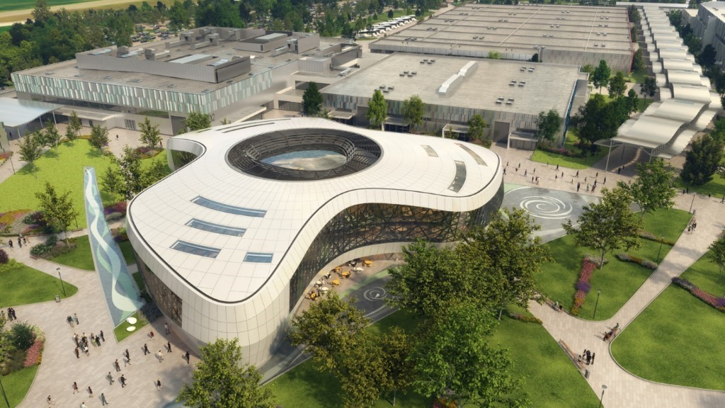
Parametric Analysis of Freeform Steel Grid Structure
In my diploma thesis I re-designed the roof structure of the Arrival Hall of Hungexpo Budapest Fair Centre.
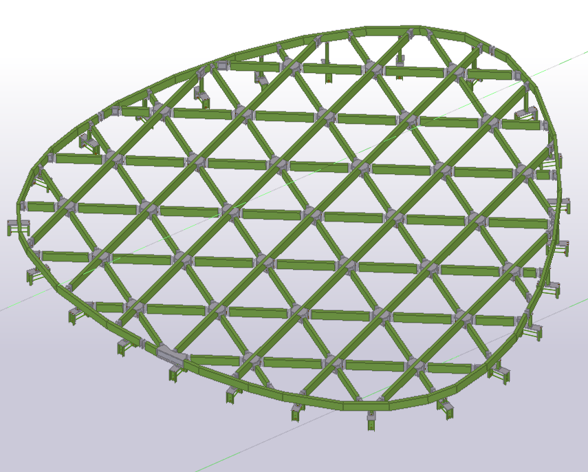
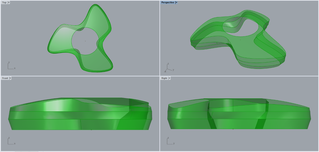
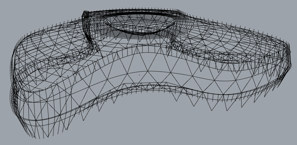
The propeller-shaped building’s enclosing size is ca. 72,0 * 67,0 metres. The facade of the building is a steel grid structure. The roof structure of the building is a steel space grid connected to the facade support structure.
The roof is supported by the steel space grid on its edges and a reinforced concrete ring in the centre. The glass structure in the middle and the walk-through mechanical yard both load on the RC ring, therefore the middle section doesn’t influence the resistance of the rest of the roof. The roof structure fits on a spherical shape.
Since this is a freeform structure, I used Grasshopper for the design, a software backed with a solid mathematical background that allows you to easily create even more complex geometric shapes. In addition, it has the great advantage of allowing parametric design, therefore many different designs and possibilities can be examined within it.
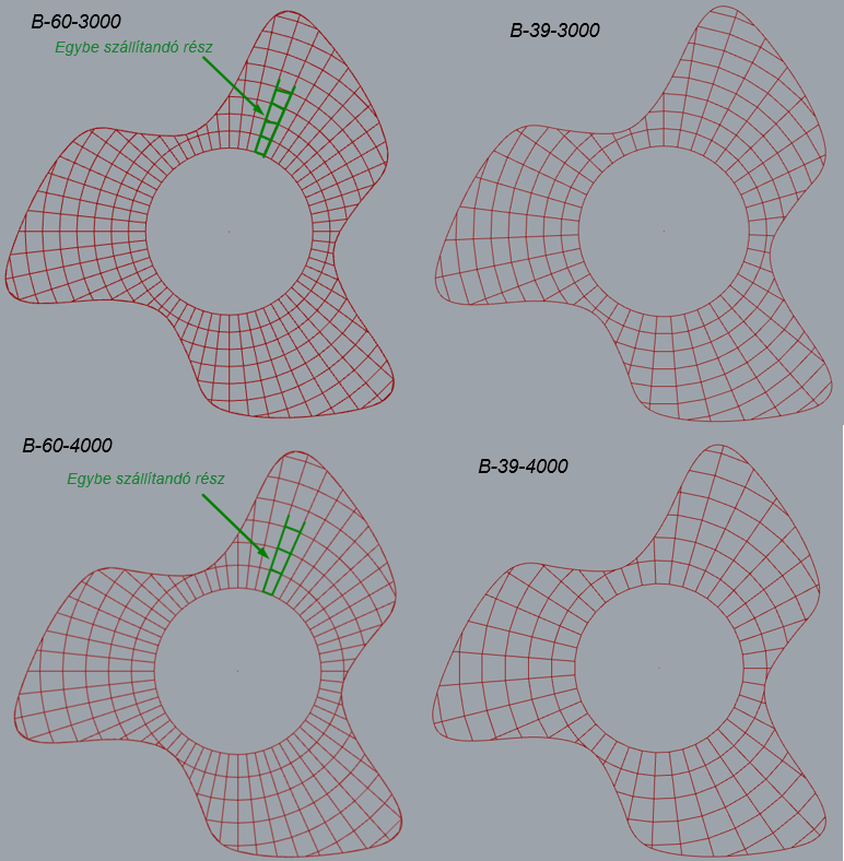
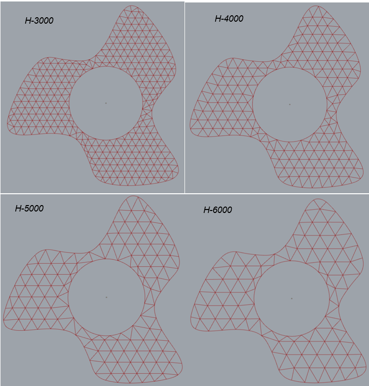
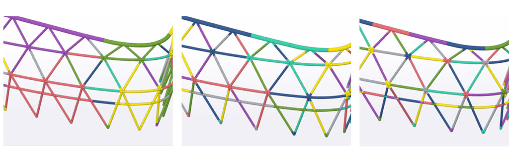
In my dissertation, I examined two types of layout: ribbed and triangular grid. Both grid systems had 4-4 subtypes that differed in their spacing ranges. I designed the different subtypes based on aspects of manufacturing, installation and transport. During the conceptual design, I examined and evaluated these 8 layouts seeking the most favourable solution among them.
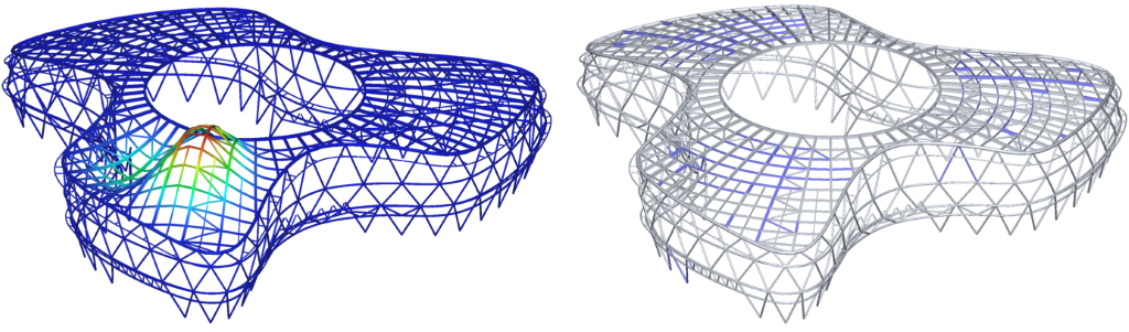
Calculations were executed in Consteel, which has a direct connection to Grasshopper through Pangolin, so I could build the static model completely parametrically.
The geometry which I created in Grasshopper is based on space curves. However, analysis software typically deals with fewer geometry options, therefore I redesigned the model to make the elements manageable in Consteel.
The goal of the conceptional design was to build a model which can be examined and compared quickly and easily, therefore I only applied one ULS and one SLS maximum load combination. With the help of the parametric model and Pangolin, I could create models in a way that while switching between parameters my Consteel model changed along, so multiple combination options could be examined easily. Apparently, I noticed both in the case of the triangle and the ribbed design, that the sections were utilized up to a certain spacing range, but at too large spacing the deflection became dominant, so the structure was no longer economical in terms of material consumption.
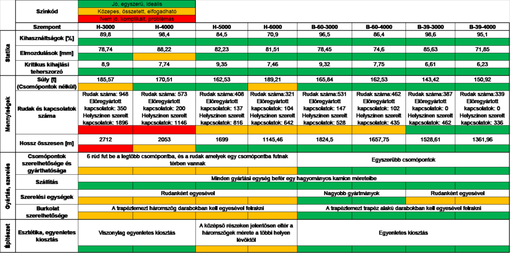
I selected the most favourable design with the help of a decision support option matrix. The great advantage of the decision support matrix is that the different designs are clearly comparable in many aspects. The evaluation was colour-coded. The criteria of the decision support option matrix were as follows:
Statics
- Maximum utilizations
- Deflections
- Critical load factors for buckling
Quantities
- Weight
- Number of beams and connections
- Full length
Manufacture and assembly
- Assembly and manufacturability of connections
- Transport
- Erection units
- Sheeting
Architecture
- Aesthetics
I colour-coded the different viewpionts
- Green – good, simple, ideal
- Orange – average, complex, acceptable
- Red – poor, compicated, problematic
Based on the evaluation the ribbed structure was proved to be best, so I carried one of the ribbed designs further for detailed calculations.
During the detailed calculation, I could apply the loads more precisely on the structure along with load combinations. Most loads acted as surface loads on the entire roof, but the wind was of different magnitudes in different zones. Here, the parametric model also had a great advantage, as being a freeform structure, I applied the wind load from 6 different directions and defined the wind zones parametrically, so changing the wind direction also changed the zones, therefore I didn’t have to define different loads on the load panels.
I also dealt with the configuration and design of the connections, for which I did calculations manually and with csJoint. It was quite instructive for me to see how much the connections influenced the main structural response. Already in conceptual design, when choosing a beam layout and defining beam end releases, it is important to consider whether connections can be designed in a way that provides adequate stiffness.
Overall, I learned a lot about design processes and parametric design during my dissertation. I think there will be an increasing emphasis on parametric design in the future, so it’s definitely worth addressing this topic.
We asked a few questions from the author, Eszter Arendt, about her experiences she gained during the project.
Interview
Consteel: First of all, congratulations on your diploma and winning the Hungarian Consteel Diploma Contest! How did you decide on the subject of your diploma?
Eszter: I was introduced to parametric design in a class held by a guest professor, and I decided right there, that I want to write in my diploma about this subject. I was lucky that bim.GROUP had already had a project which used parametric design, to which I could join, so it came naturally that I’ll write my diploma about the Hungexpo Arrival Hall. I joined the team at about halfway through the project and I worked until the end.
Consteel: What was your role in the project?
Eszter: I worked on the secondary structures mostly. The cladding was supported by a specially shaped curved profile that followed the line of the building everywhere, so these were unique profiles. I was responsible for the statics and design of this. I also helped where I needed to do connection calculations and in the design of the glass dome on the roof.
Consteel: How can a student imagine working on a project like this?
Eszter: It is full of challenges for sure. As a novice engineer, I think, you can learn a lot on any project, but for such a complex one, it was especially true in this case.
Consteel: What did you like most in this particular project?
Eszter: I liked that this was a unique project, therefore it was not boring at all, and I especially enjoyed the whole parametric design.
Consteel: What did you consider the biggest challenge in either your responsibility or in the project itself?
Eszter: The time. The construction industry is very accelerated, often with very tight deadlines. It’s challenging to get a really good job out of our hands that way. I think it’s even harder as a novice engineer, as we don’t have many years of experience, so every new task is also a learning experience.
Consteel: What Consteel function did you use most? Which part did it help your work mostly?
Eszter: I performed all the main static calculations in Consteel. Already in conceptual design, it was quite useful that I could compare different designs with simple models. I like that the stresses for connection calculations can be obtained easily and transparently. Besides, I used csJoint for the connection calculations.
Eszter: I think it has multiple advantages, but I would highlight three things:
- there is no need to place the loads manually
- changes can be tracked very simply and quickly
- many designs can be examined, thus helping conceptual design
I don’t know how I would have solved the transfer without Pangolin, maybe I would have transferred a line skeleton, but even then I would have had to build the models one by one. I think Pangolin is essential for freeform structures, but it can also be very useful for simpler tasks.
Project Facts
Eszter Arendt’s Msc diploma thesis
Consultants:
Márton István Juhász – bim.GROUP Kft.
Nauzika Kovács PhD – Budapest University of Technology and Economics, Department of Structural Engineering
Last week, on the 4th and 5th of February we held our usual yearly meeting with our resellers. It was the 10th time the Consteel Distributors got together – except this was the first time it happened online.
Usually, the distributors visit the Consteel office in Budapest on the annual distributor meetings. But this year there are no journey experiences to share, snacking on the sweet treats that a kind partner usually brings from his homeland for the team, no handshakes or getting together at all. Instead, everyone logged in from their offices, or their own homes to join the meeting. Distributors from Germany, Greece, Poland, Romania and Spain joined us to share sales experiences from 2020 and share and find out more about the plans for Consteel developments in 2021.
On the first morning, each distributor gave a presentation, summarizing last year’s events in a nutshell, and sharing their experiences in 2020 in terms of sales. We could also learn about each other’s experiences of the pandemic, in terms of business. We all had one thing in common: we had almost the same events and circumstances, for shorter or longer periods, such as social distancing, lockdowns, working from home and wearing masks everywhere. After our lunch break, we played a little online game, where everybody could show off their drawing skills on their desktop with a mouse.
The highlight of the day was the announcement of the Consteel Distributor of the Year 2020. The winner of the award this time was Strenco, our distributor in Poland. We warmly congratulate to the winner, Mr Adam Machowiak, for his great work and efforts in 2020, and wish him just as great success in the upcoming year. Sadly, we could not hand him his prize in person, so we had to do a little trick to deliver the winner his trophy. Here you can see a short video of how our „ceremony” turned out.
Our next program was a sales and marketing afternoon when we discussed some new ideas and plans for our sales activities for this new year. The following session was the introduction and preparation for the next morning’s workshop.
Friday started with the workshop: each participant had to use all their creativity. The partners could all share their opinions and brainstorm a bit about future sales possibilities.
This day could not pass without some fun after lunch either – even though we could not have our usual team building this year some more colleagues could play with us from the partner offices, which was nice. Next, it was time to introduce the new developments of Consteel 15 – which we cannot tell more about just yet, but we can assure you that we are looking ahead an exceptional year.
After a short discussion about our communications, came our last event of the distributor meeting: the traditional „Meet the Team” session. The distributor team and the Consteel team turned on their cameras and waved our „Hello” -s to each other
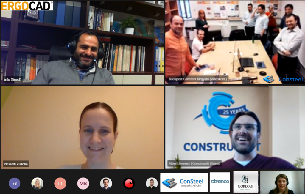
Our 10th Consteel Distributor Meeting turned out just as great as any other. However, we hope that next year we can greet each other face to face again.
The Hungexpo Budapest Fair is going through a massive revitalization. This project includes the new Arrival Hall Building, an attractive propeller-shaped building. A building with such geometric complexity requires advanced design methods and multi-platform collaboration. In this article, we aim to give an insight into the open BIM environment and parametric design methods used in the design process.
BIM Design Ltd. had various design tasks on the revitalization projects, this article will focus only on the steel design roles of Arrival Hall Building, fabrication and construction optimization, detail and erection design of the steel structure.
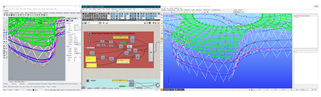
The design workflow is centred Rhino/Grasshopper, the centerline geometry is controlled here. This allows wireframe identical conceptual, structural calculations and shop detailing models. The Consteel is used for design and it is connected to Grasshopper with real-time plugins, the models are generated via visual scripting. All changes in the centerline geometry can be executed to all the models by re-running the scripts. This allows fast, detailed and multi-concept investigations through which we can improve the structure.
GEOMETRIC COMPLEXITY
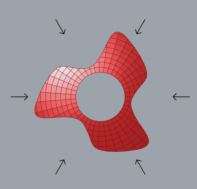
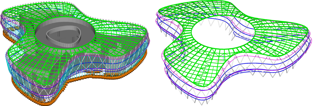
The building envelope is 120° rotationally symmetric, on top view forming 3 identical wings, resulting in a shape of a propeller. The roof surface is laid on a perfect sphere. This sphere has a circular hole in the centre and cut around with a propeller shape perimeter in the outside. The main facade is built up of 3 undulating stripes with distinct edges. These edges are horizontal on the lower levels and spatial on the roof edge, but all are ordinary curves with constantly changing curvature.
The structure can be divided into 3 parts: the facade structure, the roof structure and the secondary wall purlins. The facade is a multi-level steel truss with roughly 4-5 m wide triangle units. All steel elements are circular hollow sections. The horizontal elements follow the facade surface curvature, the inclined columns (diagonals) are straight. The roof is made of radial and circumferential elements with diagonal bracing. The radial elements are curved among the sphere surface, the circumferential elements in-between are straight beams. The wall purlins stand in a defined vertical plane harmonized with the external cladding layout.
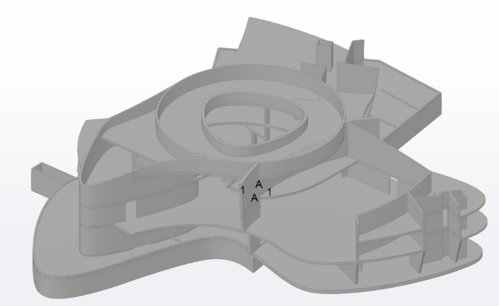
The building’s inner core, the concrete substructure does not keep the rotational symmetry, all 3 wings of the propeller show a different geometry. The load-bearing hierarchy is mixed, in some parts the steel structure supports the perimeter of concrete slabs while in other parts the concrete core supports the steel structure.
A spatial and complex building without proper control of geometry is unlikely to result in identical assemblies. Standardization is a key element in the entire construction process, it’s beneficial to reduce the number of unique assemblies. Data transfer from one software to another, the orientation of elements, local coordinate systems, varying geometric precision setups all add to this inaccuracy.
The building’s peculiarity, the 120° rotationally symmetry stays true for most of the steel structure. This property if used properly can reduce the number of unique assemblies to a third. As a base step, the received centerline geometry was corrected to fulfil this property, resulting in perfectly rotationally symmetric geometry to the fraction of a µm.
SEGMENTATION & STANDARDISATION
All construction elements must be divided into some size to deliver it to the construction site. The facade’s main unit size of the structure is a 4 m triangle, unluckily, it is not the most suitable for well-utilized standard road delivery. Three different segmentation strategy has been investigated using parametric grouping of elements. These concepts cover solutions from the smallest assemblies (joints and beams) to 5 m by 20 m curved spatial trusses. All 3 concepts have been analyzed in collaboration with the contracted manufacturer and the erector, as a result, a mixture of joints and beams, and smaller trusses were selected for detail design with trusses of maximum 2m in height at the entrances.
The roof structure has been investigated in the same way, but as a result, all elements were reduced to beams, without forming any trusses.

These parametric investigations require moderate design effort at an early stage of the project but influence significant costs and time in procurement, fabrication, fabrication logistics, delivery, site requirements, lifting and so on. These questions can be better understood and decided through with the aid of these concept models.
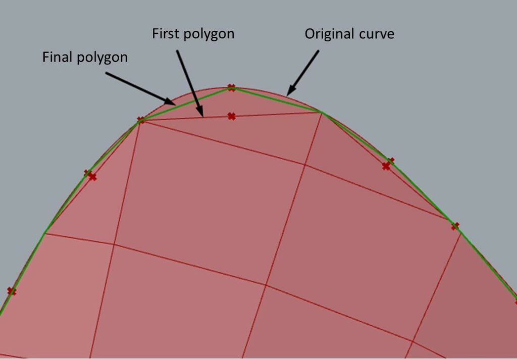
Given the delivery segmentation, another crucial task was to rationalize the ordinary curved girders while maintaining the structure visually appealing. The curves have been divided into straight and planar arc segments. Arced segments are cut perpendicular to the centerline, the resulting angle difference is always cut on the straight segments. This improves the geometric accuracy of manufacturing.
The constructor required to reduce welding on site to a minimum, therefore bolted joints were selected for most of the site connections. The bolted connections were standardized for every cross-section, to allow continuous pre-production of identical parts on the manufacturers assembling and welding robot. As a result, more than 2000 of connection sub-assemblies were manufactured with only 7 distinct splice types.
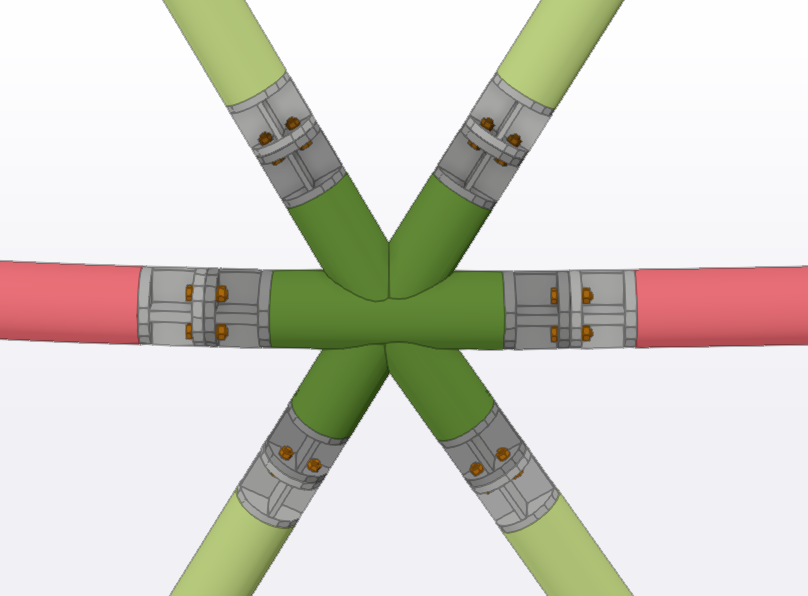
The roof structures standardization originates in the spherical roof geometry, the upper half of the radial beams, circumferential beams on a given circle are identical because centerline geometry is identical, the only condition was to keep these elements’ connection parts identical.
STRUCTURAL CALCULATION & JOINT DESIGN
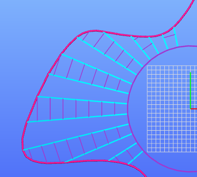
After the model was segmented to fabrication assemblies, the curved elements were rationalized to actual production parts, the next step was to check structural behaviour and section sizes. For this Consteel software was used linked to Grasshopper via the Pangolin plugin. The interface allows a real-time link between the Grasshopper script and the Consteel structural model. Receiving data back from calculation results is in development right now, however, previously created Consteel models can already be referenced in the Grasshopper script. The interface can generate almost all available Consteel objects: geometry, materials, cross-sections, structural elements, supports, loads, load groups.
The components can project the FE model in Rhino viewport similarly as it appears in Consteel, which gives constant feedback of the Grasshopper script writing. The script generates the Consteel model, the structural calculations run inside Consteel with all functionality.
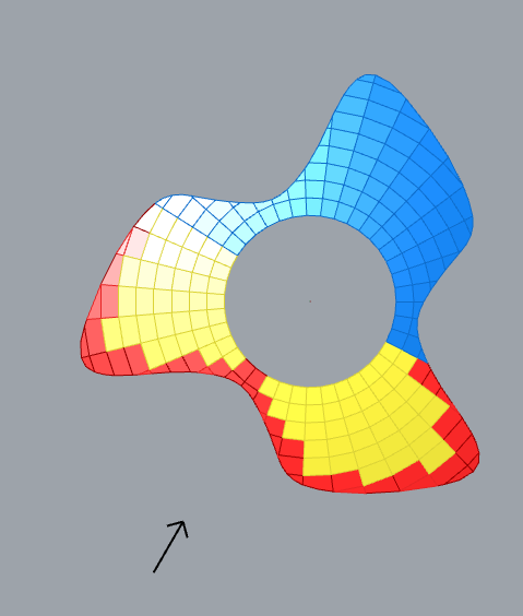
The wind coefficients of the structure were not self-evident since physical wind tunnel test was not available, and the standard does not define coefficients for such shape. As a result for the wall the coefficients we defined to be windward, leeward or sideward zones depending on the angle of the load panel’s normal vector and the wind vector. We divided the angle range two 4 equal segments. The calculated angle is between 315°-45° for the windward zone, 45°-135° and 225°-315° for side walls zone, 135°-225° for the leeward zone. The roof was considered as a double pitched roof, with intense zones on the roof edges. We investigated different 12 wind directions, 30° angles from each other, but later reduced it to 6 major wind directions which are somewhat parallel or perpendicular to the majority of the facade.
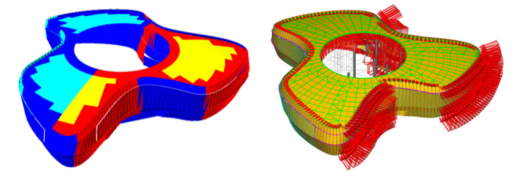
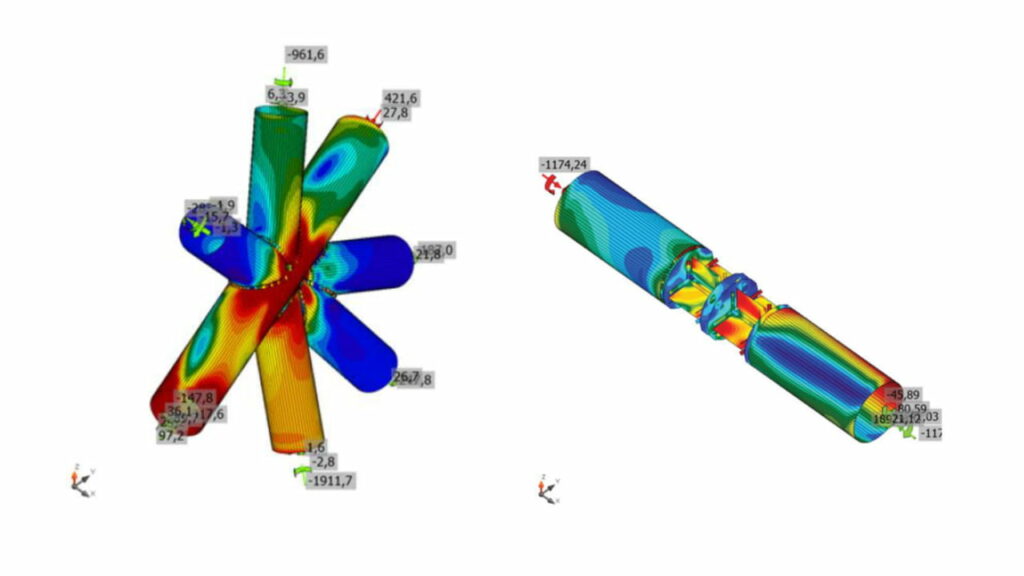
The structural analysis and standard checks are automatically performed in Consteel for the strength, stability, seismic and serviceability limit states using directly the model received from Pangolin, which resulted in a very efficient structural design workflow. All the structural elements were exported to Consteel including the steel and the concrete parts with all supports and loads, the analysis considered the complete model and the design checks considered only the steel members.
The unique analysis and cross-section models of Consteel allows the automatic calculation and check of all possible internal forces and moments, including the out-of-plane bending and torsion which caused considerable bending and warping stresses along the peripheric beams of the internal circle.
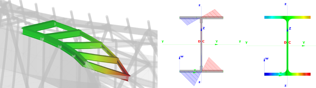
The buckling check of the members for any possible buckling mode was performed by the fully automatic unique method of Consteel based on the “General method” of 6.3.4 in EN1993-1-1 and the refined global linear buckling analysis. In this methodology, the proper member slenderness values are automatically determined by a special buckling sensitivity analysis which selects the critical members for all the relevant buckling modes.
Joint calculations have been performed in IDEA StatiCa. Similar joints were grouped and named systematically already in Grasshopper. These attributes were used for filtering governing forces and geometric extremities for each joint type. The software is linked both to Consteel and Tekla Structures, the interface transfers all necessary geometric, material, and loading data required for the joint design.
3D MODELLING & DETAILING
For steel shop detailing Tekla Structures 2019 was used. Tekla Structures is as well linked to Grasshopper, via the Tekla Live Link plugin. As of today, complete Tekla models can be generated via scripting, including all necessary fabrication attributes: sections, materially, welds, weld preparation, bolts, fabrication phase grouping etc. In our case, the Tekla model was approximately 95% generated via Grasshopper script.
This method allowed deep and iterative investigations to achieve fabrication cost efficiency and best geometric accuracy with moderate extra time and costs in design.
After the final Tekla model generation, 2d drawings and necessary fabrication documentation were prepared inside Tekla.
FABRICATION & ERECTION CONTROL
Fabrication accuracy was a key element. In an early-stage test bending of pipes and “I” beams were performed to assess the accuracy of bent elements. It did not result in bigger discrepancy than the fabrication inaccuracy of the cross-section. String height discrepancy is under ±5 mm, length tolerance is within the normal straight element limits.
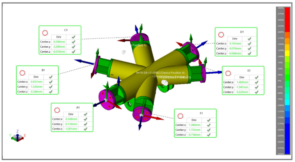
As the segmentation and detail design progressed prototype assemblies were also manufactured to investigate the accuracy of assembling. One of each major assembly types were manufactured and measured with 3d geodesic methods. The measured data was aligned on the design model with the best fit, at the connecting parts the discrepancies were calculated. In the end, the manufacturer decided to use this method not just for checking, but also to adjust assemblies prior to final welding.
The erector has performed a trial assembly of a bigger part of the facade to prove assembling compatibility. The strongest curved part of the facade was selected and assembled in a horizontal position. The structure was measured afterwards, the trial assembly showed no alerting inaccuracy.
The manufacturers’ assembly measurement values were systemized and referenced back to Grasshopper, which allowed pre-evaluation of each unique coherent joints. This data was visualized in 3d on the Tekla BIM model, which is used for predetermination of fitting plates during assembling.
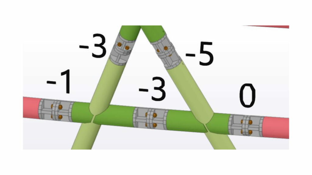
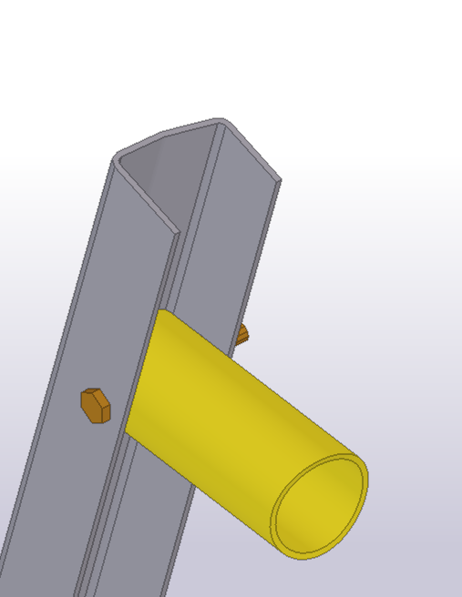
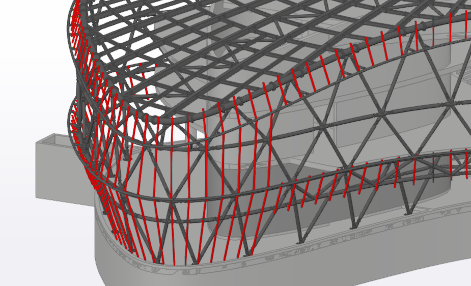
Currently, the site assembly of the steel structure is in progress. It’s planned to perform a full 3d site scan of the assembled steel structure. This measurement data will be used to adjust the secondary purlin system to all manufacturing and erection inaccuracies. Uniquely manufactured cantilevers will be welded on site which will support the cladding system.
PROJECT FACTS
Architect: Finta és Társai Építész Stúdió Ltd.
Structural Designer: Hydrastat Ltd.
Steel Detail Designer: BIM Design Ltd.
Steel Manufacturer: KÉSZ Ipari Gyártó Ltd.
Steel Erector: KÉSZ Metaltech Ltd.
Steel design team: 1 full time lead structural engineer, 2 part-time graduate engineers, 1 full-time modeller, 9 months. 2700m2, 750 tons of steel, 2000 pcs of joints on the facade, 800 pcs wall purlins.