Did you know that you could use Consteel to perform local and distortional buckling checks for cold-formed members?
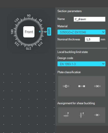
First, sections must be loaded into the model. To load cold-formed sections, you can choose from four options: From library, Macro section, Draw section, or My library.

After the first-order and buckling analyses are completed, you can proceed to the Ultimate limit state check settings and enable the steel design cross-section and buckling checks. At the bottom of the steel design section, there is an option to Consider the supplementary rules from EN 1993-1-3 for the design of cold-formed sections. This checkbox must be selected if you want to design cold-formed sections.
When the calculation is finished, by opening the Section module, we can review all the properties of the Effective section of the elastic plate segment model. By opening each plate element, we can verify the length, effective length, thickness, effective thickness, slenderness, and reduction factor separately. In addition, the properties of the stiffeners can also be verified: area, moment of inertia, lateral spring stiffness, critical stress, reduction factor, compressive stress, reduced effective area, and reduced thickness.
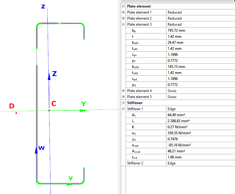
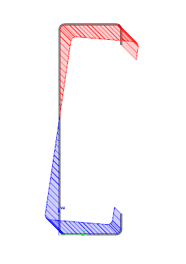
Similarly, the stresses can also be checked from the Properties tab. In the colored figure or diagram view, all the calculated stresses can be seen together with their resultants.
Consteel automatically takes into account the effect of distortional buckling when calculating the effective sections of cold-formed thin-walled sections.
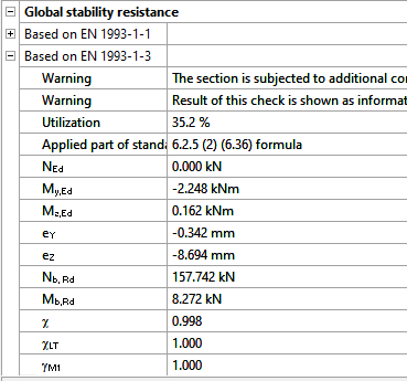
Moving on to the Standard resistance tab in the Section module, all calculated results can be verified, not only the dominant one. By opening the Global stability resistance check, we can see that, since we enabled the option to consider the supplementary rules from EN 1993-1-3 for the design of cold-formed sections, results are available both according to EN 1993-1-1 and according to EN 1993-1-3.
Download the example model and try it!
Download modelIf you haven’t tried Consteel yet, request a trial for free!
Try Consteel for freeIn our series we have shown in Part 1 and Part 2 how the spring stiffness „K” is determined for and edge and for an intermediate stiffener. In this part we will show how to proceed further.
The goal is to determine how efficiently can this stiffener support the connected compressed plate. To consider local buckling of the compressed plate the effective widths will be calculated. These widths can be either calculated for a plate supported at both ends or for a plate supported at one end only, using Table 4.1 and Table 4.2, respectively.
If a stiffener fulfills the minimum constructive requirements, we will first assume that it is rigid enough the act as a support. Based on this we work out the effective lengths for the connected compressed plates, assuming also that they are fully loaded up to the yield strength. Once we know the effective widths of the plate parts connected to the stiffener, we also know the load this stiffener is supposed to be able to carry without buckling, to justify the first assumption. Therefore, next we calculate the flexural buckling resistance of the stiffener. If we find out that it is lower than what was implicitly assumed previously, we go back to the first step, lower the stress to be compatible with the obtained buckling resistance of the stiffener (distortional buckling). This lower stress level may of course result different effective widths. An iterative procedure is started until the satisfactory result is found. After completion the final stiffener buckling resistance value will be incorporated into an equivalent effective thickness applicable for the stiffener and the connected effective plate parts.
In the above described iterative process the „K” value of the stiffener will be needed to determine the flexural buckling resistance of the stiffener. This resistance will be calculated using the help of a simple beam model, where the stabilization provided the remaining parts of the section is used as a continuous bedding of „K”. The cross section of the beam corresponds to the stiffener and connected plate parts and will be exposed to the actual stress level of the iteration, assumed as a simplification to be constant along the length. The length of the beam in this model is unknown at the moment, it should be equal to the half wavelength of the buckling shape which is expected to be around 1.5-3 times the height of the studied cold-formed section.
Distortional buckling will appear only if the length of the stiffener is much longer than this typical length range. As a further simplification Eurocode assumes infinite length as the possible worst case, because for this condition an analytic solution exists in the literature:

In this formula „K” is the spring value – shown in Part 1 and Part 2 – represents the spring stiffness value what the remaining section can provide to the stiffener. Isand Asare section properties of the corresponding stiffener together with connected effective widths of supported plates, namely area and inertia around an axis perpendicular to the expected direction of buckling of the stiffener. E is the Young modulus of the steel material.
The formula gives the critical stress level where elastic buckling would appear. Once this has been found, reduced slenderness is calculated, and the distortional buckling resistance can be obtained by using a special buckling curve given by (5.12a-c) formulas of EN 1993-1-3.
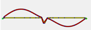
The validity of formula (5.15) can be easily demonstrated with a simple Consteel model.
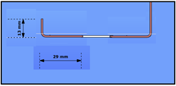
Let’s assume the Z section from our 1st blog exposed to compression force and let’s assume that we have already calculated effective width values. Yield strength of the material is 235 MPa and coating thickness is 0.04 mm. We found that the effective width of the lip and flange are ceff=13 mm and beff=29 mm, respectively.
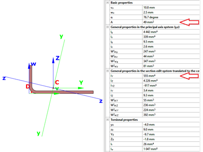
The section properties can be calculated with Consteel
Distortional buckling – Further secret formulas of EN 1993-1-3. Check our article for the first secret formula if you hadn’t read it yet.
In our series we continue with the second „secret” formula of EN 1993-1-3.

This formula (5.11) is used when the ability of an intermediate stiffener to stabilize a compressed web plate is studied.
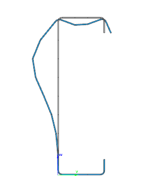
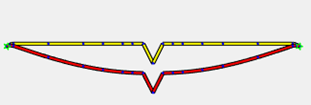
When the intermediate stiffener is rigid enough, it divides efficiently the longer web plate into shorter plates. During buckling a rigid stiffener will not displace and the plate will buckle between the ends (stabilized by flanges) and this stiffener:
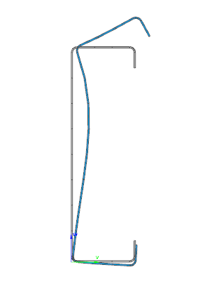
If the stiffener is not rigid enough, already at a much lower stress level the distortional buckling will appear which is characterized by a displacement of the stiffener and by the web plate buckling with a half-wave equal to the plate length:
In such a case Eurocode still accepts that web plate buckling will occur between ends and intermediate stiffener, but reduces the thickness of the intermediate stiffener zone, to compensate for the less than ideal rigidity. This compensation will depend on the buckling resistance of the stiffener when subject to compression.
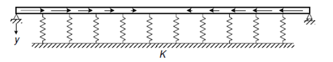
The simplified model used by Eurocode in the procedure can be seen below. As a simplification it is assumed that the web plate is connected to the rest of the section with hinges. It means that it’s buckling shape is not influenced by the stiffness of connected parts, they do not encaster its ends, its ends can freely rotate. The ends of the plate are supported and there the plate can provide an elastic bedding to the stiffener, which will be considered as a „help” when its buckling resistance will be determined. This bedding is represented by the K spring stiffness:
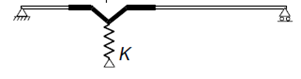
The spring value which represents in this model the bedding provided by the plate is calculated as the ratio of the displacement obtained from the application of a unit load at the center of gravity of the stiffneer. In this case the unit load is applied perpendicularly to the web plate. Formula (5.11) gives the deflection (δ) from such unit load (u).
gate