Did you know that you could use Consteel to calculate effective cross-section properties for Class 4 sections?
The classification of cross-sections is used to understand how local buckling affects the strength and rotation capacity of structural members. As stated in Eurocode 3 (EN 1993-3-3, Section 5.5), this classification helps determine whether a cross-section can reach its full resistance or if its behavior is limited by local instability.
Class 4 cross-sections are those in which local buckling occurs before the material reaches the yield stress in one or more parts. Because of this, their resistance must be calculated using effective section properties that take into account the reduction caused by local buckling.
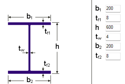
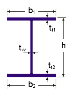
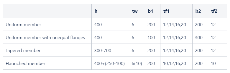
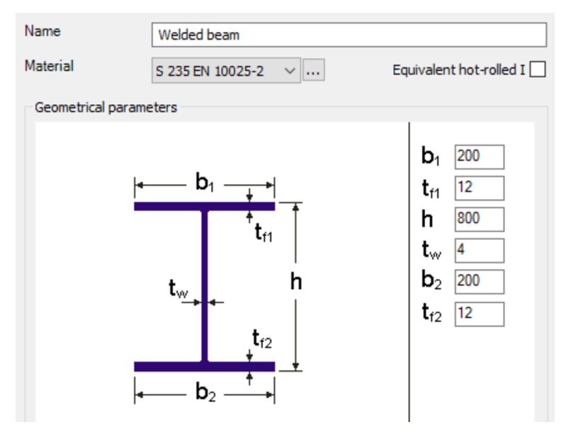
Typical Class 4 sections are characterized by slender elements with high width-to-thickness ratios. These commonly include thin webs or flanges, hollow sections (RHS/CHS) with slender walls, thin-walled cold-formed profiles such as C- or L-sections, and welded I-sections with slender webs. In this example, we consider a welded I-section with the following geometric parameters:
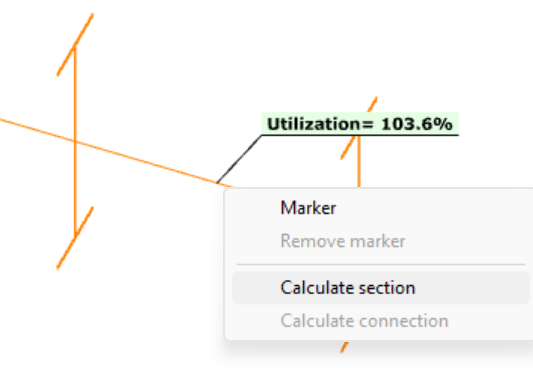
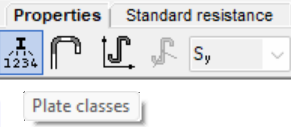
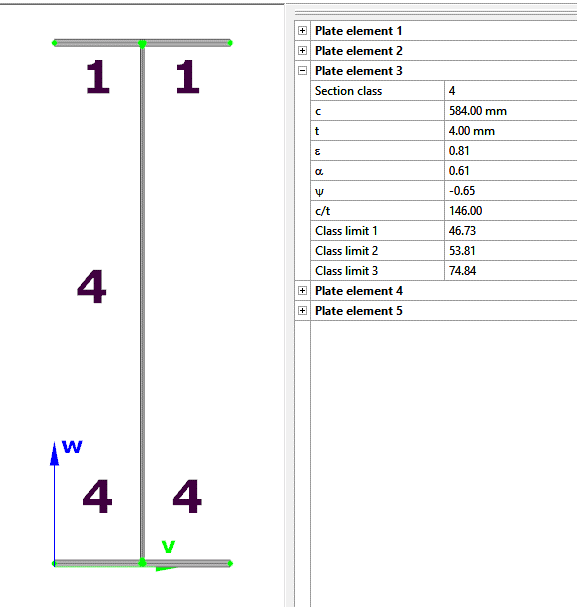
In Consteel, we can then see the section classification from the Global Checks tab. After selecting the investigated section either in the model or from the table and clicking on the Calculate Section option, and then choosing the Plate Classes in the Properties tab.
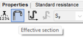
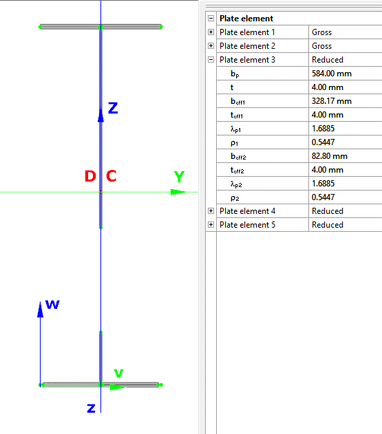
The effective section properties can then be viewed using the second option in the Properties tab.
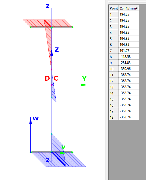
In addition, stresses can be visualized by clicking on the Stresses icon. They can be represented either as a colored figure or as a 3D diagram.
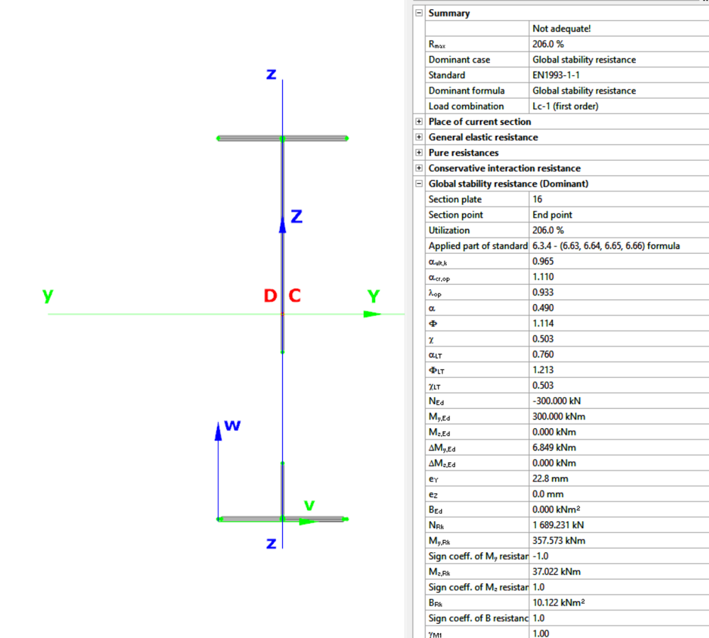
For Class 4 sections, the Standard Resistance tab in the section module provides a complete assessment for the selected loading case.
The section module performs all necessary calculations according to the Eurocode (EN 1993-1-1 and relevant parts of EN 1993-1-5), including general elastic resistance, pure case resistance, conservative interaction checks, and web buckling analysis.
All resistances are calculated using the effective section properties to account for local buckling, and the module identifies the dominant case to ensure all relevant checks are covered.
Download the example model and try it!
Download modelIf you haven’t tried Consteel yet, request a trial for free!
Try Consteel for freeIntroduction
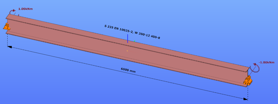
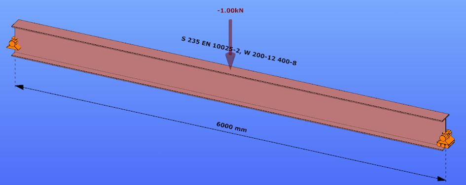
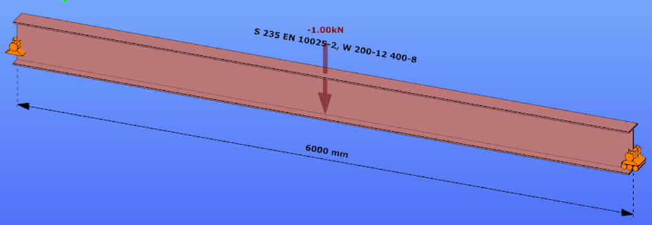
This verification example studies a simple fork supported beam member with welded section (flanges: 200-12; web: 400-8) subjected to bending about major axis. Constant bending moment due to concentrated end moments and triangular moment dsitribution from concentrated transverse force is examined. Critical moment and force of the member is calculated by hand and by the Consteel software using both 7 DOF beam finite element model and Superbeam function.
Geometry
Constant bending moment distribution
Triangular bending moment distribution – load on upper flange
Triangular bending moment distribution – load on bottom flange
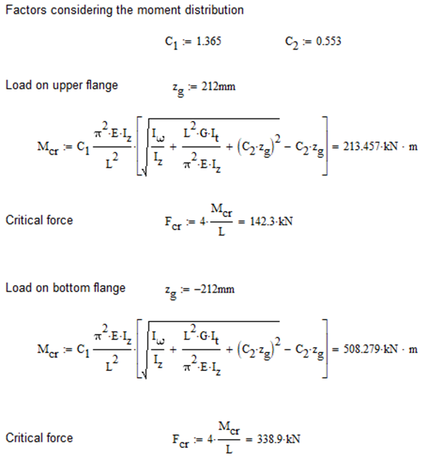
Calculation by hand
Constant bending moment distribution

Triangular bending moment distribution
Computation by Consteel
Version nr: Consteel 15 build 1722
Constant bending moment distribution
7 DOF beam element
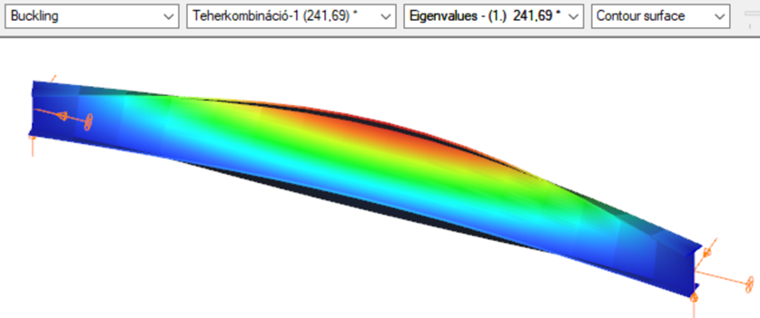
First buckling eigenvalue of the member which was computed by the Consteel software using the 7 DOF beam finite element model (n=16). The eigenshape shows lateral torsional buckling.
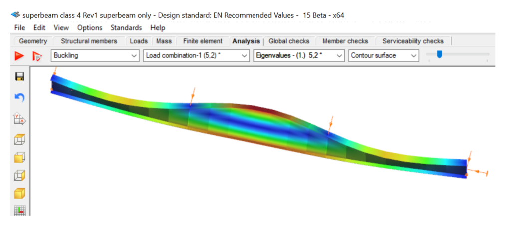
Superbeam
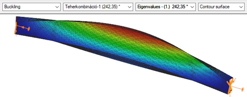
First buckling eigenvalue of the member which was computed by the Consteel software using the Superbeam function (δ=25).
Triangular bending moment distribution – load on upper flange
7 DOF beam element
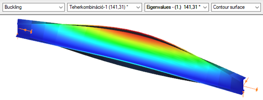
First buckling eigenvalue of the member which was computed by the Consteel software using the 7 DOF beam finite element model (n=16).
Superbeam
First buckling eigenvalue of the member which was computed by the Consteel software using the Superbeam function (δ=25).

Triangular bending moment distribution – load on bottom flange
(more…)Introduction of Consteel Superbeam
In general, Consteel uses 7 DOF beam elements for finite element analysis of steel structures which are adequate for most everyday design situations. It is also capable of using shell elements in order to get more precise results in cases where beam finite elements are not sufficient enough. With the new Superbeam function it is now possible to examine structural parts with the accuracy of shell elements but with the ease of using a beam element concerning definition, modification, model handling, etc. In practice, it means that 7DOF beams can be switched to shell elements (and back) at any stage of the design process.
Validation
The validation program aims to verify the full mechanical behavior of the Superbeam switched to and analyzed as shell elements within a structural model composed of 7DOF beam elements. The validation of the analysis of the shell finite elements was done before and it is clear that in the case of correctly set boundary conditions the results are the same as the beam model provided that the local web buckling effect is avoided because it can not be modeled with beam-theory. Therefore the accuracy of the mechanical behavior of the Superbeam basically depends on two major factors:
- 1. the automatic shell modeling and mesh of the Superbeam
- When transforming a beam model in the structural analysis to shell model, several automatic transformations are done with the model objects (loads, supports, connected elements etc.) in order to yield a consistent mechanical model.
- 2. the mechanical consistency of the connections of Superbeam at the boundary to 7DOF nodes
- To satisfy the mechanical consistency at the connecting nodes the Superbeam uses automatically set constraint elements at both ends. They ensure the compatibility of the complete displacement field (translations, rotations, and warping) with the adjacent 7DOF beam finite element node or with the 7DOF point support.
The validation studies prove that the beam analysis model is mechanically equivalent to the shell analysis model within the Superbeam by comparing the results of the two models. It is shown that
- in the case of models where the local plate-like specific behavior is not relevant (thick plates in the cross-secions) the results are the same
- in the case of models where the local plate-like specific behavior is relevant (thin plates in the cross-secions) the results can be different only because of this plate-like behavior (local buckling, cross-section distortion) while the isolated beam-like behavior is the same
Part 1
In this first part of the validation, we examined simply supported beams of welded I-sections with several different profile geometries. The full length of the beams was changed to Superbeam shell and so the consistency of results of both the shell elements and the constraints could be analyzed.
Structural models and analysis
In every case, the beam was first calculated with 7 DOF beam finite elements, after with Superbeam shell elements, and finally also as a full shell model with the same finite element sizes as the Superbeam shell. In full shell models, we applied rigid bodies along the edge of the web.
Linear buckling analysis was executed in order to compare the first buckling eigenvalues.
Our expectation was that the two kinds of shell models would produce very similar results which are by nature somewhat less favorable than the 7 DOF beam results, meaning that alfa critical values should be lower when using shell elements. To be able to compare the results related to global (lateral-torsional) buckling, the effect of local buckling of the web was to be avoided as much as possible so the examples were chosen accordingly.
Geometry
Loading
gateIntroduction
Beam with welded I sections are often executed with slender webs. This is mainly due to the recognition that the main contributors to bending stiffness of a beam are the flanges. The web plate’s main role is to safely keep these flanges away from each other and carry the shear stresses which might be present. Significant weight saving can be achieved with the use of slender webs, but there are some aspects to take care about.
When slender web plates are exposed to longitudinal, uniform normal stresses, above a certain stress level its distribution will no longer remain uniform. A compressed region of a plate distant from its lateral supports may buckle in a direction perpendicular to the acting external normal stresses, causing a subsequent transfer of stresses from the affected region to other neighbouring regions remaining in their unbuckled position.
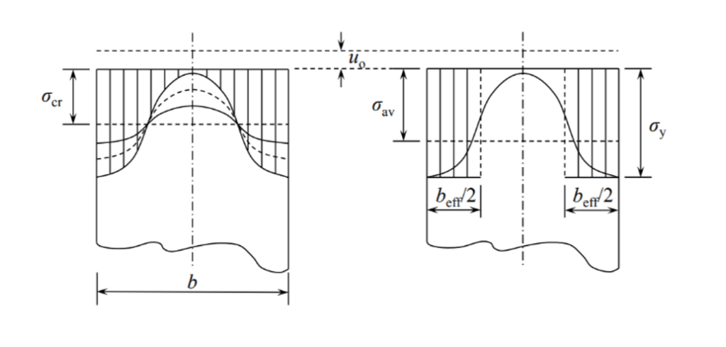
This buckling remains limited to a part of the plate keeping other parts intact and therefore is called as local buckling. Local buckling usually does not result an immediate collapse of the structure, due to possibility of the stresses to redistribute and often even a substantial amount of further load increases are possible.
The tendency of a compressed plate to suffer local buckling is characterized by its slenderness value defined by the following formula
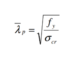
where σcr is the critical stress level above of which the stress redistribution and local buckling starts to appear. A higher critical stress will result in lower slenderness value which indicates that the plate can carry higher compressive stresses without the initiation of local buckling.
Analysis of cross-sections with beam finite elements
The well-known beam finite elements used by usual structural design software do not “see” the internal composition of the cross-section. During structural analysis the sections are represented by certain integrated cross-sections properties assuming the validity of several assumptions including the Bernoulli-Navier Hypothesis and the non-deformability of the cross-section. A local buckling of any of its internal plates would violate these assumptions making hard to create the equivalent cross-sections properties.
In the modern design practice followed by Eurocode the phenomenon of local buckling is handled by the use of effective section properties. Regions subject to possible local buckling of compressed plates of a cross-sections are “eliminated” and the section properties are calculated based on the remaining parts of the cross-sections.
Design verifications use these effective cross-section properties to calculate the resistance of cross-sections exposed compressive forces. When required by Eurocode, the effect of appearance of local buckling can also be reflected in a structural analysis using beam finite elements with the use of effective cross-section properties, instead of the original gross section properties. This is mainly required to prove serviceability criteria.
Analysis of cross-sections with Consteel Superbeam
The Consteel Superbeam function makes possible to confirm directly the presence of local buckling using the same beam element based model, but using a mixed beam and shell finite element modelling and analysis approach. Using the Superbeam tool, complete structural members or parts of them can be alternatively modelled with shell elements and the rest can still be modelled with beam finite elements. Using this technique, the total degrees of freedom of the model can be kept as low as possible. When using Superbeam, the designer has the choice whether to use beam or shell finite elements, as appropriate.
Contrary to beam finite elements, modelling with shell finite elements doesn’t have the previously mentioned limitations. This approach can fully consider the shape and location of the cross-section’s internal components instead of the use of an integrated overall section property. When a linear buckling analysis (LBA) is performed, the critical stress multipliers corresponding to the actual stress distribution can be obtained. Additionally to the load multipliers, the corresponding buckling shapes are also available, giving direct indication on the location, shape and appearance of local buckling within the compressed parts of the cross-section.
The use of effective cross-section concept is very convenient but there might be cases when more insight view is desired. The following example gives an idea where the Superbeam function can be helpful.
Demonstrative example
Let’s consider a 12 m long simple supported welded beam with the following parameters
The beam is laterally restrained at third points at the level of its upper flange. The beam is loaded with its self-weight plus a uniformly distributed load of 10 kN/m acting at the level of upper flange.
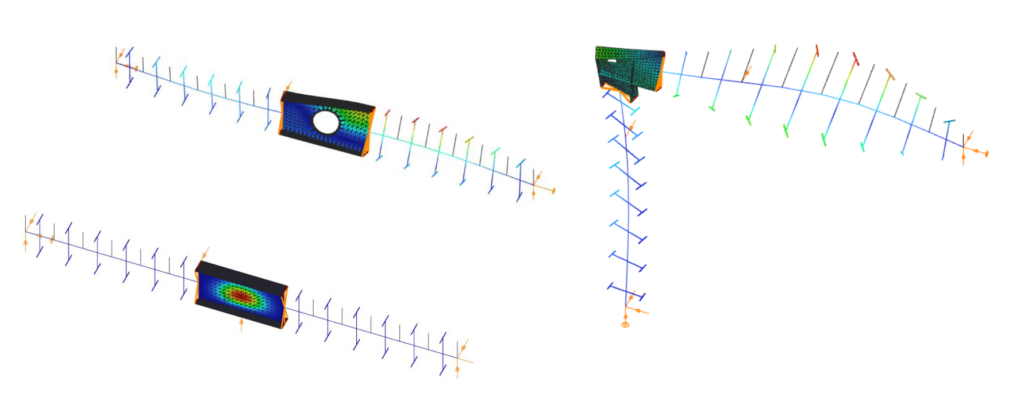
When the beam is analysed with 7DOF beam finite elements, one can obtain the critical load multiplier of 5.2 of the global buckling mode, which is lateral-torsional buckling (LTB) in this case.
The beam finite element cannot give any visible indication about possible local buckling in compressed plates of the cross-sections.
As the maximum bending moment occurs in the middle third of this beam, it seems enough to analyse this part mode deeply with the Superbeam function. An LBA with the mixed beam and shell model gives comparable critical multiplier of 5.22 with some numeric perturbances in the part modelled with shell elements.
gateThe new versions of the EN 1993-1-1 (EC3-1-1) and the EN 1993-1-5 (EC3-1-5) standards have introduced the general method designing beam-column structures; see [1] and [2]. The design method requires 3D geometric model and finite element analysis. In a series of papers we present this general design approach. The parts of the series are the following:
- Part 1: 3D model based analysis using general beam-column FEM
Click the button bellow to download and read the full article.
gate