
Did you know that you could use Consteel to Consider the shear stiffness of a steel deck as stabilization for steel members?
In many practical steel structures, trapezoidal decking is treated only as a load-bearing surface. In reality, when properly connected to the supporting members, it behaves as a shear diaphragm and contributes to the overall stability of the structure. This effect can be directly taken into account in Consteel by applying shear field stiffness to beam elements.

The stabilizing effect comes from the in-plane shear stiffness of the deck. Under horizontal loading, the sheeting deforms and transfers forces between structural members. This behavior can be described by a single parameter, the shear stiffness (S), which represents the resistance of the diaphragm against deformation.
The overall stiffness is influenced by several components, including the shear deformation of the sheet, profile geometry, fastener slip, and connection flexibility. These contributions together define how effectively the deck can restrain phenomena such as lateral-torsional buckling.
A key requirement for this behavior is proper fastening. Typically, the sheeting must be connected along its edges and fixed to supporting members at each rib to ensure reliable diaphragm action.
In engineering practice, shear stiffness is determined using standardized or manufacturer-based methods rather than detailed analytical models. Consteel supports several established approaches:
- Schardt/Strehl method (DIN 18807), based on parameters describing shear and warping deformation
- Improved Schardt/Strehl method, including the effect of fastener spacing
- Bryan/Davies method, considering additional structural parameters
- Eurocode-based method, using general geometric properties of the sheeting
These methods differ in complexity and required input data, but all aim to provide a realistic stiffness value for use in global analysis. If the sheeting is not fixed at every rib, the calculated stiffness must be reduced accordingly.
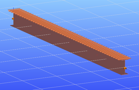
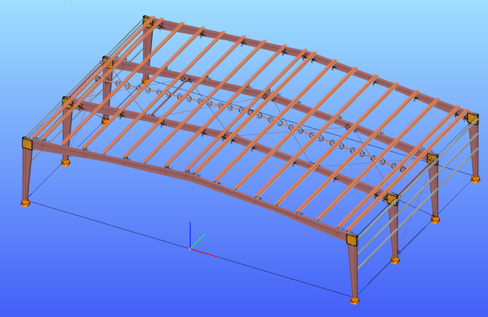
The shear field object in Consteel allows engineers to include the diaphragm effect without detailed shell modeling. The calculated shear stiffness can be assigned directly to beam elements, providing additional lateral restraint.
The process involves selecting a trapezoidal sheet profile, choosing the appropriate calculation method, and defining the relevant geometric and connection parameters. The software then determines the stiffness and incorporates it into the structural model.
Including shear stiffness in the analysis can lead to higher critical load factors and reduced displacements, resulting in more efficient structural designs. However, it also means that the decking becomes part of the stabilizing system.
Any later modifications to the sheeting, such as openings or changes in fastening, may reduce this effect and should therefore be carefully assessed.
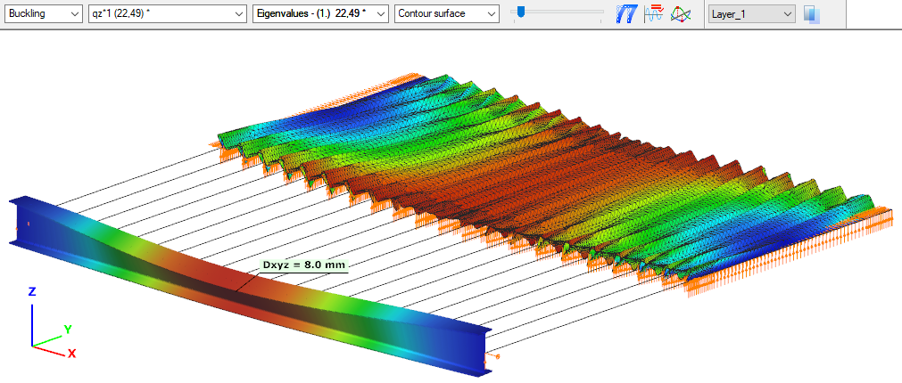
The shear stiffness of trapezoidal steel decking provides a measurable and often significant contribution to structural stability. By incorporating this effect in Consteel, engineers can achieve more realistic analysis results and optimize their designs while maintaining structural safety.
Download the example model and try it!
Download modelIf you haven’t tried Consteel yet, request a trial for free!
Try Consteel for freeIntroduction
Are you wondering how a web opening would influence the lateral-torsional buckling resistance of your beam? Check it precisely with a Consteel Superbeam based analysis
It is often required to let services pass through the web of beams. In such cases the common solution is to provide the required number of opening in the webplate. Such an opening can have a circular or rectangular shape, depending on the amount, size and shape of pipes or ventilation or cable trays.
Beams must be designed to have the required against lateral-torsional buckling. The design procedure defined in Eurocode 3 is based on the evaluation of the critical bending moment value which provides the slenderness value, needed to calculate the reduction factor used for the design verification.
There is no analytical formula provided in the code for beams with web openings. Would the neglection of such cutouts cause a miscalculated and unsafe estimation of the critical moment value?
The following demonstration will be made with a 6 meters long simple supported floor beam with a welded section.
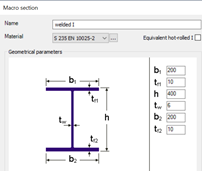
Exposed to a linear load of 10 kN/m, the critical bending moment value of the solid web beam can be obtained by performing a Linear Buckling Analysis (LBA) with Consteel.
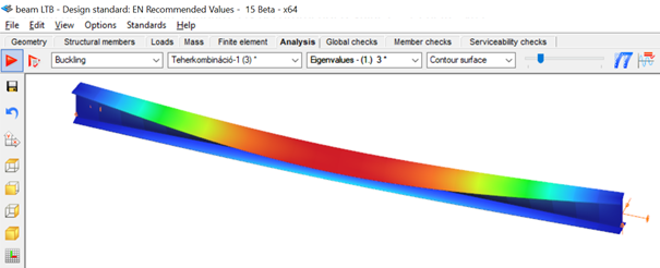
The obtained critical multiplier for the first buckling mode is 3.00 which means that the actually applied load intensity can be multiplied by 3.00 to reach the critical load level. The corresponding critical moment will have the value of Mcr = 3.0 * 47.18 = 141.54 kNm yielding a slenderness of 1.286 (Mpl,Rd = 234.20 kNm) and a lateral-torsional buckling resistance of 0.394 * 234.20 = 92.27 kNm. With this value the actual utilization ratio is at 51%.
How would this value change if a rectangular opening needs to be cut into the web of this beam?
Analytical formula for critical bending moment
By looking to the analytical formula (ENV 1993-1-1 F.4) to calculate the critical moment of double symmetric sections loaded at eccentric load application point it becomes obvious that the section properties having effect on the moment value are Iz, Iw and It.

An opening in the web has no effect on the first two values and has very little effect on the last one. As it has been already shown in previous article, the presence of such an opening can have effect on the vertical deflection, but as long as the lateral stiffness of a beam is much lower than it’s strong axis stiffness, the vertical deflections can be neglected when the lateral-torsional buckling resistance is calculated. The usual linear buckling analysis (LBA) performed also by Consteel neglects the pre-buckling deformations.
Therefore one can expect that in general web openings can be disregarded when the critical moment value is calculated.
Analysis with Consteel Superbeam
Beam finite elements cannot natively consider the presence of web openings. In order to obtain the precise analysis result, it is possible to use shell finite elements. The new Superbeam functionality comes as a solution in such cases. Instead of using beam finite elements, let’s use shell elements!
Opening can be positioned easily along the web, either as an individual opening or as a group of openings placed equidistantly. The opening can be rectangular, circular or even hexagonal. Circular openings can be completed with an additional circular ring stiffener.
The rectangular opening for this example can be easily defined with this tool. As there is no need to provide any additional opening on the remaining part of the beam, only the first part which includes the opening will be modelled with shell elements and the rest can still be modelled with beam finite elements. Using this technique, the total degrees of freedom of the model can be kept as low as possible. When using Superbeam, the designer has the choice whether to use beam or shell finite elements, as appropriate.
gateAfter introducing the Eurocode standards several theses have been published on the now much-discussed phenomenon of lateral-torsional buckling of steel structural elements under pure bending. According to that, researchers are working on the development of such new design methods which can solve the problems of the design formulae given by the EN 1993-1-1. This paper gives a detailed review of the proposals for novel hand calculation procedures for the prediction of LT buckling resistance of beams. Nowadays, the application of structural design softwares in practical engineering becomes more common and widespread. Recognizing this growing interest, the main objective of our research work is the development of a novel, computer-aided design method. In this paper, the details of a general type stability design procedure for the determination of the LT buckling resistance of members under pure bending are introduced. Here, the theoretical basis of the proposed method is clarified, the calculation procedure is detailed and some results for the evaluation of the appropriateness of the method are also presented. Based on the evaluations it can be stated that the new, general type design method is properly accurate and has several advantages on the stability check of beams under bending
Click the button bellow to download and read the full article.
gate