- Inhalte
Calculate the elastic critical moment of a member subject to arbitrary loading and boundary conditions
Did you know that you could use Consteel to calculate the elastic critical moment of a member subject to arbitrary loading and boundary conditions?
Calculating the elastic critical moment can quickly become difficult when beams have tapering, unusual restraints, or complex loads. Consteel simplifies the process and gives a quick, accurate result for any situation.
The elastic critical moment for lateral-torsional buckling is the theoretical bending moment at which a beam, free to sway sideways and twist, becomes unstable and buckles elastically, before yielding, representing the absolute upper limit of elastic stability for beam bending. It depends on: cross-section stiffness properties (Iz, Iw), material (E, G), span / buckling length, restraint to lateral displacement and to warping at the restraints, and on the shape of the moment diagram (via factors C1, C2, C3).
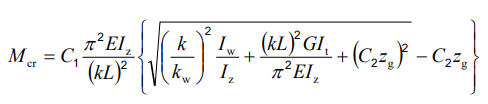
For doubly symmetric I- or H-sections with constant cross-section, uniform bending, and classical boundary conditions, the elastic critical moment Mcr can be calculated using the analytical formula:
However, for arbitrary support conditions and loading scenarios, the calculation becomes significantly more complex, and the classical formula is no longer applicable. In such cases, specialized software such as LTBeam or Consteel is required.
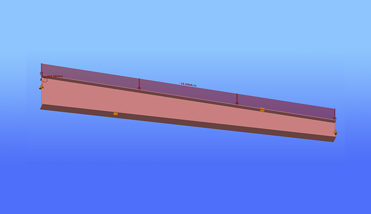
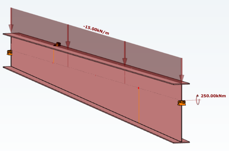
Let’s consider a tapered, welded I-section with pinned supports at both ends and two intermediate restraints, one at the bottom flange and one at the top flange. In addition to the uniform distributed load, a bending moment is applied at one end of the beam.
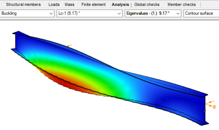
By performing a buckling analysis in the Analysis tab, the buckling shapes and the critical load factor (αcr) can be obtained. The elastic critical bending moment of the beam can be then calculated by multiplying the critical load factor by the maximum bending moment.
Consteel uses seven-degree-of-freedom finite element that fully accounts for tapering effects, torsion, and warping, key components in accurately capturing the true 3D behaviour of steel members. The seventh degree of freedom represents cross-sectional warping, which becomes visible in the buckling shape as the flanges move out of the plane of the cross-section.
Download the example model and try it!
Download modelIf you haven't tried Consteel yet, request a trial for free!
Try Consteel for free