Introduction
In Consteel there is a possibility to perform a model check on the structure to reveal modelling errors. This model check or diagnostics can be separated to First and Second level model diagnostics.
How it works
The First level diagnostics runs automatically before starting the analysis. It contains two types of checks. First a quick check is running which verfies the minimum conditions of creating the finite element mesh. The second one is a geometrical check performed on the generated finite element mesh verifing for example if the loads and supports are actually on the structure or if there are overlaps between bar or surface elements.
The Second level diagnostics can be initiated manually at any time during the modelling stage to examine the current state. The function can be launched by clicking onView/Diagnostics…button. It starts also with the same quick check as the first level. Then a basic check is running examining e.g. too small distances between members or unproperly supported model parts.
It is recommended to perform second level diagnostics after the modelling of the structure to reveal errors coming from inaccuracies of the modelling. After these errors had been fixed, it is OK to proceed to the analysis, which will automatically trigger the first level diagnostics. If it still reveals model errors, it is easier to handle them if all of the problems from second level diagnostics had been fixed.
Diagnostic messages
There are two kinds of diagnostic messages:
ERRORS: They make the calculations impossible or meaningless to execute so the detected errors stop further calculations.
POSSIBLE ERRORS: The warnings allow the calculation to run but they can influence the results.
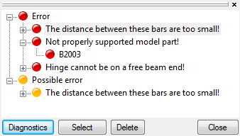
By clicking on any of the object name in the tree structure and pressing the SELECT button, the selected object will be highlighted in the model graphical surface. The selected object can be erased by pressing DELETE button, or it can be modified with the regular geometric operations.
Tutorial video
To see the use of the diagnostic tool, please watch one of our earlier tutorial video below:
gateIntroduction
In the last years, freeform architecture became more and more popular. A variety of complex geometric shapes are used for the facades of buildings, which brought the demand of new, innovative tools and solutions for modelling of these structures too. In Consteel we have developed such functions to make the engineers‘ work easier.
Section orientation
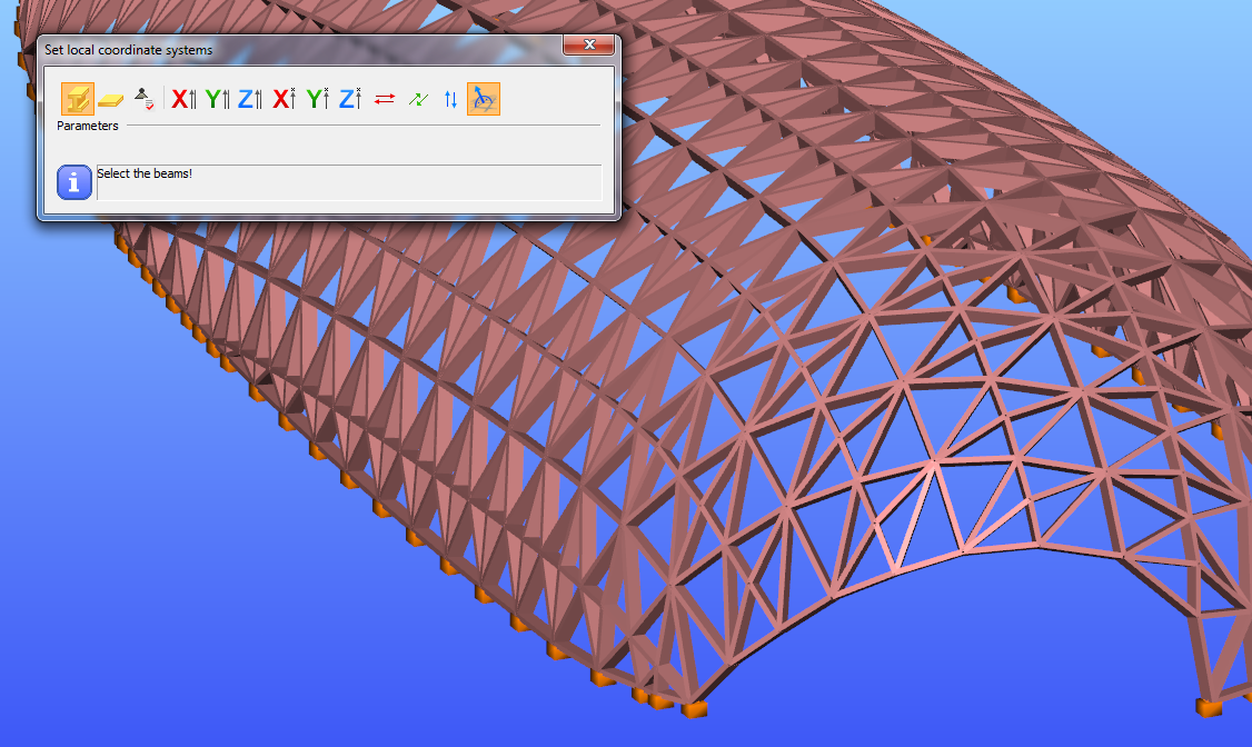
Orientation of the sections is always a problem. We have implemented a tool, with which the rotation of the sections can be done automatically. Sections can be rotated perpendicularly to the surface of the freeform shape of the structure. Z axis will be perpendicular to the surface formed by the connecting beams.
Load transfer surfaces
Covering a freeform structure with load transfer surfaces -like in the picture below-manually, would take a lot of time and effort. Our tool for multiple load transfer surface placement gives you a quick, easy and effective solution for covering your freeforms.
gateIntroduction
It happens quite often, that you need to import static models from another modeling software into Consteel. This is a very practical and effective solution to simplify your work. However, it is very important that the original model is accurate. If not, it could easily lead to unpleasant problems for the user.
How it works
In the example given below, there was a very small distance between the endpoints of some of the columns.
Consteel has an automatic correction algorithm that attempts to correct assumed modelling errors like this by merging nearby nodes. So the error correcting algorithm moves the top node of the column to the bottom node of the other.
After that, the column is no longer vertical. When running the analysis, there will be a message that “the columns are not exactly vertical”. It is only a warning message to inform you that your column is not vertical for some reason and it is up to you to decide whether or not to change that. If you decide to make the column vertical, you can do it easily. Please watch the video and follow the steps below.
gateIntroduction
In Consteel there are several opportunities to place the point supports you need in a quick and effective way.
Multiple placing of column bases
In case you imported a model from another software and there are no supports defined or for some reason you decided to define the supports after modelling the whole building, it is not necessary to place every support one-by-one by clicking the end of all of the columns. To save time, click Multiple placing function (black arrow) on Point support dialog after setting the support type and select the columns with selection window.
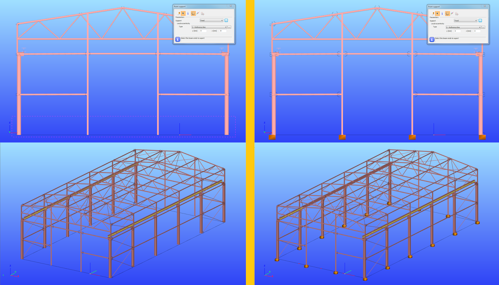
Multiple placing on members
It is also possible to use the Multiple support function of the same Point support dialog to place the supports representing the girts/purlins and flange braces of a frame. Distribution and eccentricity of the supports can be defined. If the distribution given is not suitable for the member, Consteel will ignore the distances which are outside the member length (3rd 1600mm on the picture below) even if there is another member with the same reference line.
gateIntroduction
The Frame corner wizard is a useful additional function for modelling and analyzing the corner region in order to consider its special behavior.
What is it for
The frame corner zones have usually significantly different behavior than the beam elements connected to each other without significant angle between their reference line. Frame corner wizard recognises the corner regions and applies special methods during modelling, buckling analysis and global checks. Using this function will provide very similar analysis results compared to where the frame is modelled with shell elements.
But in order to that, the topology of the frame corner must be defined by the user. Four different types can be chosen. The 7. DOF displacement is transferred differently in every case. To learn more technical details of the frame corner types, please see our user manual.
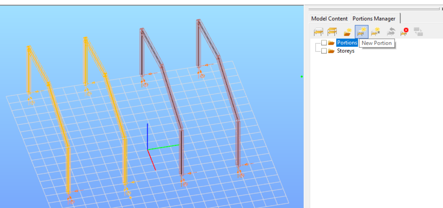
How to use it
At first define Portions of the model containing all the structural elements you intend to connect with the same type of corner topology.
Introduction
How can you place surface wind loads, when you have a custom shaped flat roof instead of the standard types you can see in Eurocode?
How to do that
Create a load transfer surface to the roof with Draw polygon option at Edit load transfer surface dialog.

Open Create surface load dialog and choose Draw and Wind load option.
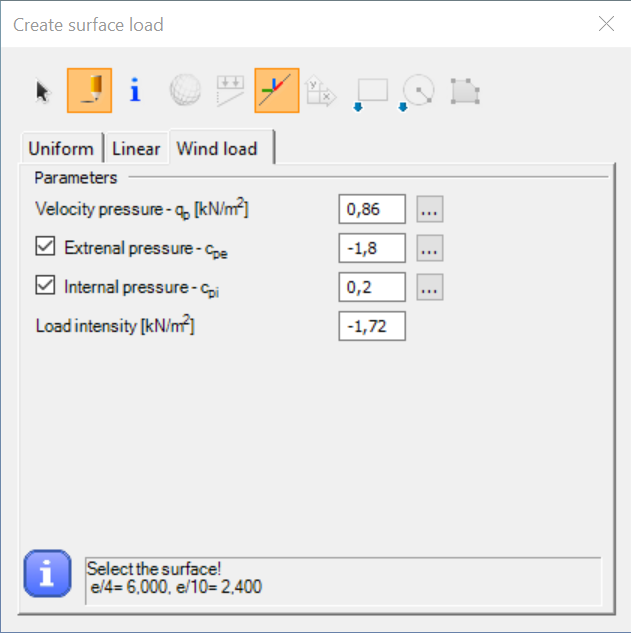
Set the parameters – load intensity will be calculated automatically:
Velocity pressure can be defined either manually or by clicking on the … and setting the parameters.
To calculate the zones and Cpe values click on the … at External pressure – Cpe. When defining the b and d values use the overall dimensions of the building of the current wind load direction. The zones will be calculated to cover this theoretical surface.
gateThe problem
Even if all of the load combination generation formulas of EN are implemented in Consteel for the automatic generation of combinations, standard formulas may not cover every necessary combination cases.
A quick fix
Of course in this case it is possible to define the missing combinations manually, but it is very likely, that the missing combinations are available, probably in a table form.
It is good to know, that Consteel is able to receive combination data, by the general Ctrl+C & Ctrl+V method. If you have the factors for load combinations stored in table form e.g. in Excel, just copy the data of the factors to the clipboard with Ctrl+C, and then Ctrl+V paste them into Consteels’s load combination table:
gateThe portal frames composed of tapered welded I-shaped structural members play important roles in the industrial buildings. The application of the relatively thin plates and the optimized fabrication makes these structures being competitive against the light truss structures at least in the range of 24–36 meters span. Competition has resulted in lesser selfweights using thin plated slender cross-sections, which are sensitive to local buckling. However, the development of structures concerning local buckling was delayed in Hungary by the conservative specifications of the MSz 15024 standard. The application of the new EN 1993 standard may cause radical development in the design of tapered structural elements with relatively thin plates. This paper introduces the methods as well as the advantages of the new design methodology.
Clich the button below to download and read the full article. The article is in hungarian at page 42-55.
gate