Rácsos tartó szerkezet méretezése
A rácsos tartók globális (rúdszerkezeti szintű) méretezése nem igényel különleges elméleti ismeretet: rendszerint a hajlítónyomatékok és a nyíróerők elhanyagolásával a rácsos tartók rudjait nyomott és/vagy húzott rúdként méretezzük. A nyomott rudak méretezését manapság modell alapú számítógépes eljárással hajtjuk végre. Ennek részleteit lásd a Nyomott rúd méretezése kihajlás ellen című tudásbázis anyagban. Itt csak a nyomott rudak kihajlási hosszának meghatározását mutatjuk be.
A nyomott rúd méretezésénél a legfontosabb paraméter a rúdkarcsúság:
$$\overline{\lambda}=\sqrt\frac{Af_y}{N_{cr}}$$
ahol
$$N_{cr}=\frac{\pi^2El}{(kL)^2}$$
ahol a k kihajlási hosszt (befogási tényezőt) az EN1993-1-1 szabvány, a kézi számítások megkönnyítése érdekében, az alábbiak szerint javasolja felvenni:
| Nyomott rúd típusa | Kihajlás iránya | k |
|---|---|---|
| övrúd | – tartó síkjában – tartó síkjára merőlegesen | 0.9 0.9 |
| rácsrúd | – tartó síkjában – tartó síkjára merőlegesen | 0.9 1.0 |
A modell alapú számítógépes eljárásokon alapuló szoftverek (pl. a Consteel szoftver) a fenti konzervatív szabály helyett az Ncr rugalmas kritikus erőt közvetlenül végeselemes numerikus módszerrel, a teljes rácsos tartó viselkedésének figyelembe vételével, határozzák meg. Az alábbi példával a szabvány által javasolt kézi méretezési eljárás és a modern, modell alapú numerikus eljárás eredményének viszonyát kívánjuk szemléltetni.
- Legyen a vizsgált rácsos tartó szerkezeti modellje az 1. ábrán látható Consteel modell.
- A feltűntetett teher feleljen meg a tartó mértékadó tervezési teherkombinációjának.
- Határozzuk meg a legjobban igénybe vett nyomott övrúd kihajlási hosszát végeselemes numerikus stabilitási analízis segítségével.
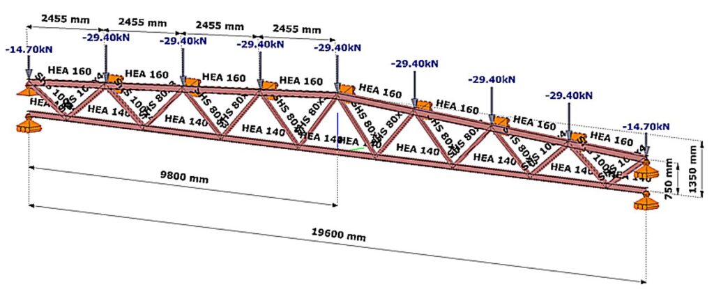
(Consteel szoftver)
Eljárások összehasonlítása
A számítás lépései a következők:
Rugalmas stabilitási analízis
A rugalmas modell stabilitási analízise megmutatja, hogy a rácsos szerkezet mértékadó stabilitásvesztési módját és az ahhoz tartozó αcr rugalmas kritikus teherszorzót (2. ábra).
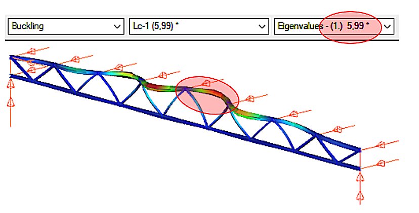
Láthatjuk, hogy a terhelés hatására a tökéletesen rugalmas modell felső öve oldalsó irányban kihajlást szenved. A teher, amely hatására a rugalmas kihajlás bekövetkezik, a kritikus teher, amelynek értékét a tervezési teher és az αcr=5.99 kritikus teherszorzó szorzata adja meg.
gateA nyomott rúd méretezésének fejlődése
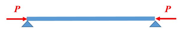
A rudakból épített acélszerkezetek (pl. rácsos tartók) egyik jellegzetes alkotó eleme a nyomott rúd. Nyomott rúdról akkor beszélünk, ha a rendszerint egyenes tengelyű szerkezeti elem központos P nyomóerővel terhelt (1. ábra).
A 2. ábra a nyomott rúd méretezésének fejlődését illusztrálja. Kezdetben (a régi időkben) az építőmesterek az évszázadok során felhalmozódott tapasztalati ismeretek alapján, amelyek mesterről tanítványra szálltak, állapították meg a különböző anyagú és méretű nyomott oszlopok teherbírását. Jelentős változást a klasszikus matematikai differenciálanalízis mérnöki alkalmazása hozott. Euler (1707-1783) svájci matematikus és fizikus megoldotta a nyomott rugalmas vonal kihajlásának problémáját, amely megoldás alkalmazható volt a rugalmas nyomott rúd megoldására (Euler erő). A mérnökök a következő évszázadokban felismerték, hogy az Euler erő csak bizonyos esetekben (elsősorban nagy karcsúságoknál) ad elfogadható közelítést a nyomott rúd valós teherbírására. Számos, az Euler képletnél fejlettebb megoldás született a nyomott rúd teherbírására, de jelentős változást csak a II. világháborút követő hatalmas szerkezetépítési konjunktúra hozott. A világ minden számottevő szerkezeti laboratóriumában sorra végezték a nyomott rúd kísérleteket, majd az eredményekből összeállítottak egy több mint kétezer kísérletből álló adatbázist. A nyomott rúd teherbírását az adatbázis alapján, a matematikai statisztika módszerével meghatározott képlettel adták meg.
Ez a módszertan a mai napig meghatározó: „a nyomott rúd méretezése az acélszerkezeti szakma politikai kérdése lett…”. Ezért a nyomott rúd méretezési elvének megértése a szerkezet-építőmérnök számára alapvető fontosságú.
Az ábra jobb oldala a jövőre is tartalmaz utalást. A tudományos kutatás szintjén már jelen, hogy a valós nyomott rúd teherbírását matematikai-mechanikai szimulációval is meg lehet határozni. Sőt, a közeljövőben minden eddigi ismeretet meghaladó adatbázisok hozhatók létre a szuperszámítógépek bevetésével. Egy ilyen gigantikus adatbázis alapján a mesterséges intelligencia felülírhatja az eddigi mérnöki tudást és módszertant, legalábbis elvben. A valóság viszont az, hogy a szerkezet-éptőmérnökség nem tartozik a húzóágazatok közé (mint például a hadipar vagy az autóipar), ezért ez az új méretezéselméleti váltás még egy jó ideig bizonyosan várat magára.

A továbbiakban a ma acélszerkezeti mérnöksége számra kiemelten fontos Euler erőt és a kísérleti alapú szabványos méretezési formulát tárgyaljuk részletesen.
Az ideális nyomott rúd teherbírása: az Euler erő
Tételezzük fel, hogy az alábbi ábrán látható csuklósan megtámasztott nyomott rúd rendelkezik az alábbi tulajdonságokkal:
- tökéletesen egyenes,
- az anyaga tökéletesen lineárisan rugalmas,
- központosan nyomott.
A fenti feltételekkel végezzük el a nyomott rúd kísérletet a Consteel szoftver segítségével: futtassuk a lineáris kihajlási analízis (Linear Buckling Analysis, LBA) számítást. Az eredményt a 3. ábra szemlélteti.
gateDid you know that you could use Consteel to perform local and distortional buckling checks for cold-formed members?
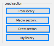
First, sections must be loaded into the model. To load cold-formed sections, you can choose from four options: From library, Macro section, Draw section, or My library.
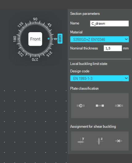
After the first-order and buckling analyses are completed, you can proceed to the Ultimate limit state check settings and enable the steel design cross-section and buckling checks. At the bottom of the steel design section, there is an option to Consider the supplementary rules from EN 1993-1-3 for the design of cold-formed sections. This checkbox must be selected if you want to design cold-formed sections.
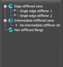
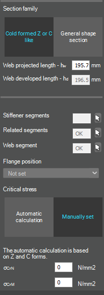
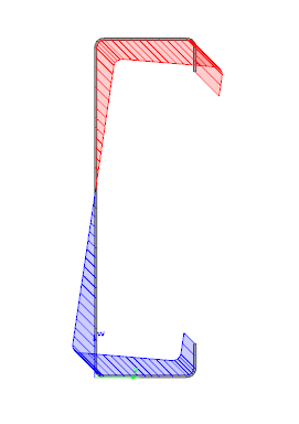
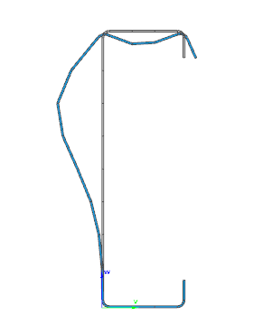
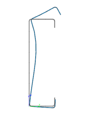
When the calculation is finished, by opening the Section module, we can review all the properties of the Effective section of the elastic plate segment model. By opening each plate element, we can verify the length, effective length, thickness, effective thickness, slenderness, and reduction factor separately. In addition, the properties of the stiffeners can also be verified: area, moment of inertia, lateral spring stiffness, critical stress, reduction factor, compressive stress, reduced effective area, and reduced thickness.
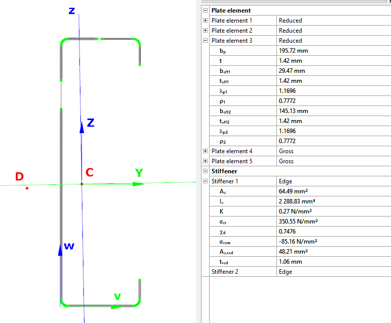
Similarly, the stresses can also be checked from the Properties tab. In the colored figure or diagram view, all the calculated stresses can be seen together with their resultants.
Consteel automatically takes into account the effect of distortional buckling when calculating the effective sections of cold-formed thin-walled sections.
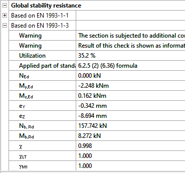
Moving on to the Standard resistance tab in the Section module, all calculated results can be verified, not only the dominant one. By opening the Global stability resistance check, we can see that, since we enabled the option to consider the supplementary rules from EN 1993-1-3 for the design of cold-formed sections, results are available both according to EN 1993-1-1 and according to EN 1993-1-3.
Download the example model and try it!
Download modelIf you haven’t tried Consteel yet, request a trial for free!
Try Consteel for freeThis paper discusses a combination of best practices and procedures from recent work in Europe and the US, providing rational and economical calculations addressing the complexities associated with frame design using nonprismatic members. Recommendations are provided in the context of US design practice. A primary objective is to achieve maximum simplicity, transparency, and design speed while facilitating rigor of the underlying calculations. The paper provides several focused examples illustrating the recommended design verification procedures.
Click the button below to download and read the full article.
GATEThe practical use of the ‘General method’ of EN 1993-1-1 6.3.4 for the buckling design of global structural models is still a challenging issue requiring several problems to solve. In this paper we propose a fully developed methodology presenting solutions for the application topics such as the suitable FE model, specific modeling issues to capture the true 3D behavior of the members and the whole model and the final evaluation of the design parameters. The presented methodology consistently uses a unique model for the evaluation of all analysis and design parameters and results and yields a fully automatic design process controlled solely by the properly created structural model.
Click the button bellow to download and read the full article.
gateWarehouse building example for Overall Imperfection Method in Consteel

Watch our user guide about How to use the Overall Imperfection Method to learn more.
gateOverall Imperfection Method in Consteel
The Overall Imperfection Method is an alternative way to carry out the buckling design for a structural member. With this method the buckling phenomenon is considered on the effect side of the equation, instead of on the resistance side, compared to the general method and the member check method. In the following video we explain the theoretical background for this calculation. After that we present application examples starting with the simplest ones, all the way to the most general case in a real-world building structure, showcasing the several extra capabilities and advantages of the Overall Imperfection Method.
Check out our user guide to learn more!
gateConsteel 14 is a powerful analysis and design software for structural engineers. Watch our video how to get started with Consteel.
Contents
- Set design parameters
- Perform cross section check
- Examine the design results in the Section Module
- Stability design according to the general method
- Member check – stability design for members
- Serviceability check
Part 2 – Imperfection factors
The Eurocode EN 1993-1-1 offers basically two methods for the buckling verification of members:
(1) based on buckling reduction factors (buckling curves) and
(2) based on equivalent geometrical imperfections.
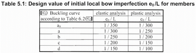
In the first part of this article, we reviewed the utilization difference and showed the relationship between the two methods. It was concluded that the method of chapters 6.3.1 (reduction factor) and 5.3.2 (11) (buckling mode based equivalent imperfection) are consistent at the load level equal to the buckling resistance of the member, so when the member utilization is 100%. The basic result of the procedure in 5.3.2 (11) is the amplitude (largest deflection value) of the equivalent geometrical imperfection. However, the Eurocode gives another simpler alternative for the calculation of this amplitude for compressed members in section 5.3.2(3) b) in Table 5.1, where the amplitude of an initial bow is defined as a portion of the member length for each buckling curves (Fig. 1.). We use the first column (“elastic analysis”) including smaller amplitude values.
It is an obvious expectation that these two standard procedures should yield at least similar results for the same problem. However, this is by far not the case in general.
In order to show the significance of the imperfection amplitudes this part is dealing with these two calculation methods, the variation of their values and the effect on the buckling utilization.
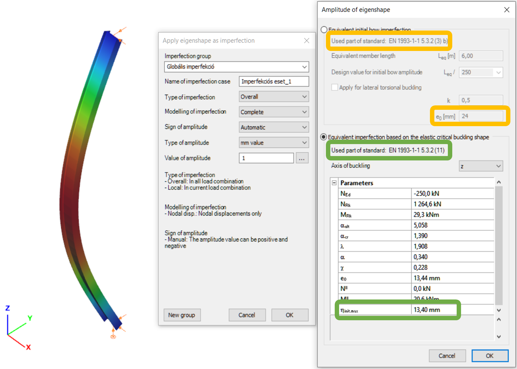
Let’s see again the simple example of Part 1: a simply supported, compressed column with a Class 2 cross-section (plastic resistance calculation allowed). The column is 6 meters high and has an IPE300 cross-section made of S235 steel. The two methods are implemented into Consteel and on Figure 2. it can be seen, that the two values for the amplitude of the geometrical imperfection is very different – e0 = 24 mm by the 5.3.2(3) b) Table 5.1 (L/250) and e0 = 13,4 mm by the 5.3.2 (11) (same as in Part 1).
Introduction
There are different ways to evaluate the stability of a structure. It is important to know the differences between those methods and the limits of applicability but it is also important to recognize the equalities in pure cases.
Methods of stability design
In Eurocode 1993-1-1, and so in Consteel, there are 3 methods to verify the stability of a model:
- Imperfection approach (described in Section 5.2 and 5.3)
The structural model is subjected to appropriate geometrical imperfections and after completing a second order analysis, only the cross section resistances need to be checked
- Isolated member approach ( described in section 6.3.1, 6.3.2 and 6.3.3)
The method is based on two essential simplifications:
- Structural member isolation: The relevant member is isolated from the global structural model by applying special boundary conditions (supports, restraints or loads) at the connection points which are taken into account in the calculation of the buckling resistance
- Buckling mode separation: The buckling of the member is calculated separately for the pure modes: flexural buckling for pure compression and lateral-torsional buckling for pure bending. The two effects are connected by applying special interaction factors.
- General method (described in section 6.3.4)
The basic idea behind the general method is that it no longer isolates members and separates the pure buckling modes, but considers the complex system of forces in the member and evaluates the appropriate compound buckling modes. The method offers the possibility to provide solutions where the isolated member approach is not entirely appropriate:
-The general method is applicable not only for single, isolated members, but also for sub frames or complete structural models where the governing buckling mode involves the complete frame.
-The general method can examine irregular structural members such as tapered members, haunched members, and built up members.
-The general method is applicable for any irregular load and support system where separation into the pure buckling modes is not possible.
Implementation of different approaches in Consteel
Isolated member approach is basically the reduction factor method and it can be performed in Member checks function in Consteel where it is possible to define the design parameters (e.g. effective length) by hand.
In Global checksfunction, cross-section and global buckling checks can be executed automatically according to the General method which does not require the direct introduction of effective lengths and other parameters depending on the distribution and combination of stresses along the member.
However, in pure cases (pure compression, or pure bending), buckling length calculated from general method can be equated with isolated member approach. In the following, a „how to” example will be shown on a pure compression column:
How can I get the buckling length of a certain member?
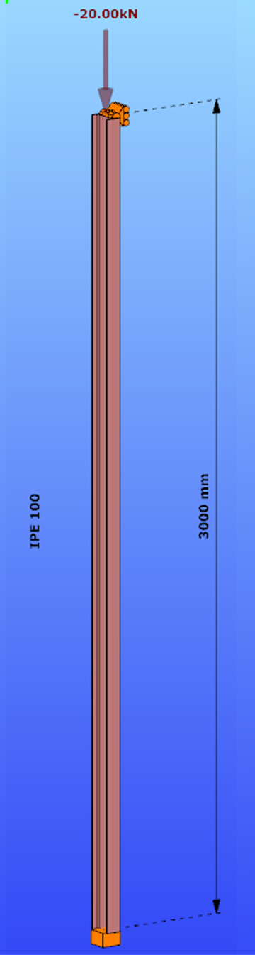
Parameters:
- Section: IPE100
- Material: S235
Main inertia around axes:
- Iy = 1708644 mm4
- Iz = 158056 mm4
Supports:
- x,y,zz on the top
- fixed on the bottom
Load: NED = 20 kN
Both the Isolated member approach and the General method require to calculate the slenderness value of the member. In case of the first method this is done through the use of buckling lengths. By using the General Method, the slenderness is calculated as the ratio of two amplifiying factors.
For the calculation of the equivalent buckling length we will need the first amplifier only, called critical elastic factor or alpha critical factor, obtained through a numerical analysis called linear buckling analysis.
Determination of alpha critical factor with buckling analysis:
Alpha critical factor: Minimum amplifier for the design loads to reach the elastic critical resistance of the structural component with regards to lateral buckling.
gate