Did you know that you could use Consteel to build 3D models with smart link elements which automatically adapt the model when profiles are changed?
Link elements are used to connect members that are not directly joined. In Consteel, three types of link elements are available: Link, Smart Link, and Constraints.
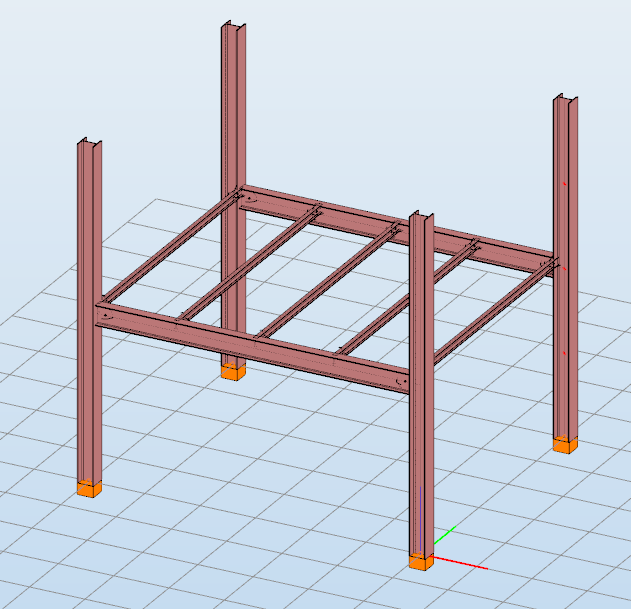
A smart link is a dynamic connection element designed to simplify the management of geometric changes between connected members. It automatically follows the movement, rotation, or profile changes of the primary member it is attached to, while also ensuring that any connected secondary member adapts accordingly.
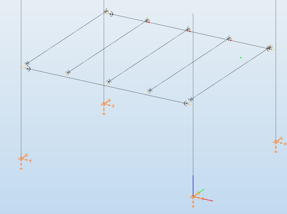
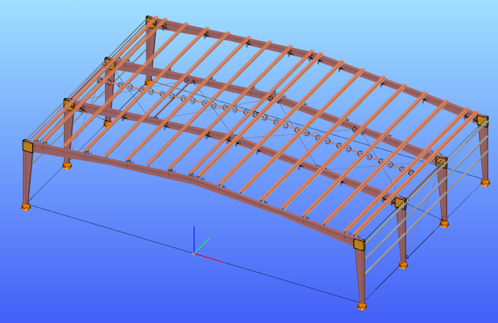
A common application is connecting a main beam to a purlin or other secondary elements, with smart links positioned at specific points. They enable easy attachment of additional members while preserving the defined eccentricity, and automatically adapt to any changes in the main beam’s geometry or profile.
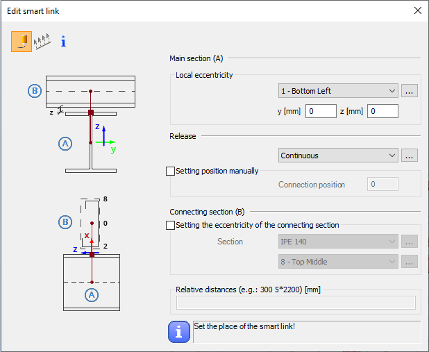
The Smart Link function, located on the Structural Members tab, opens the Edit Smart Link dialog box after activating the command. This allows you to:
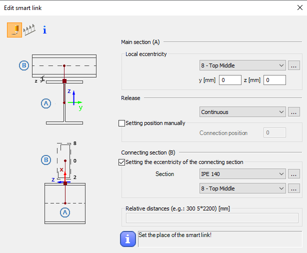
- define the eccentricity of the link relative to the main section
- set the connection type in the Release field
The connection position can be specified manually or left to default automatically to the edge of the main member.
Defining the connecting section is optional. When specified, an eccentricity can be assigned, and the program automatically determines the link length based on the section height and reference point.
Smart links can be placed individually by clicking on a member or in groups by specifying distances from the member’s start. Any placement conflicts are indicated by a warning.
By combining associative behavior with precise control, Smart Links support efficient and reliable 3D modeling in Consteel. They help maintain structural intent throughout design changes, reduce manual corrections, and improve overall model consistency.
For workflows where geometry evolves and secondary members must remain accurately connected, Smart Links provide a clear advantage and enable a more resilient and adaptable modeling process.
Download the example model and try it!
Download modelIf you haven’t tried Consteel yet, request a trial for free!
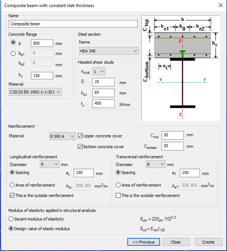
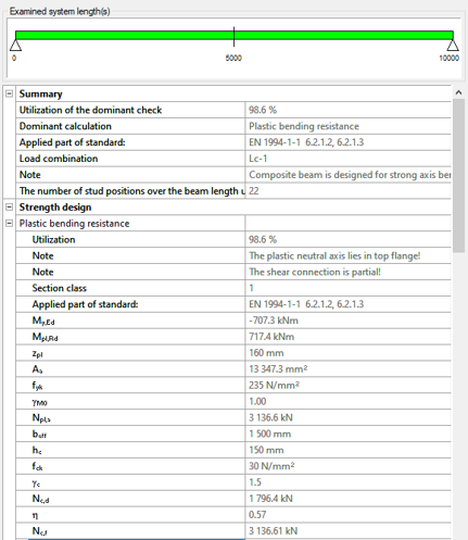
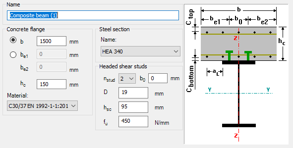
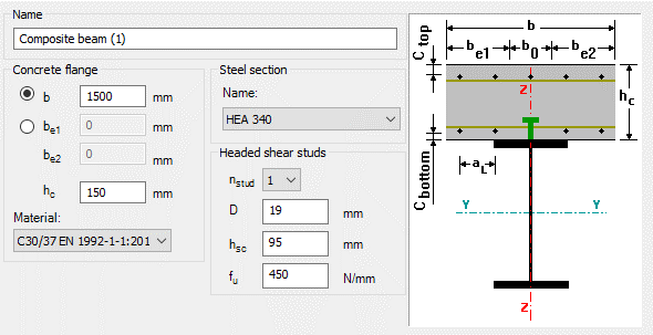
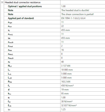
Try Consteel for freeDid you know that you could use Consteel to determine the optimum number of shear connectors for composite beams?
Download the example model and try it!
Download modelIf you haven’t tried Consteel yet, request a trial for free!
Try Consteel for free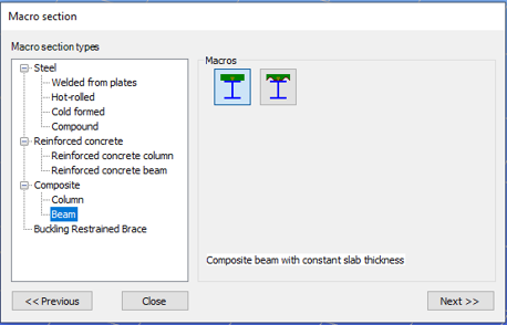

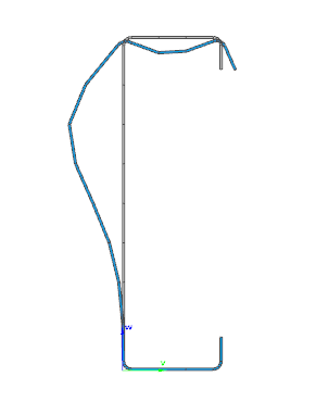
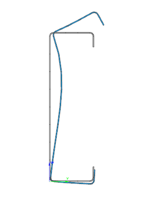
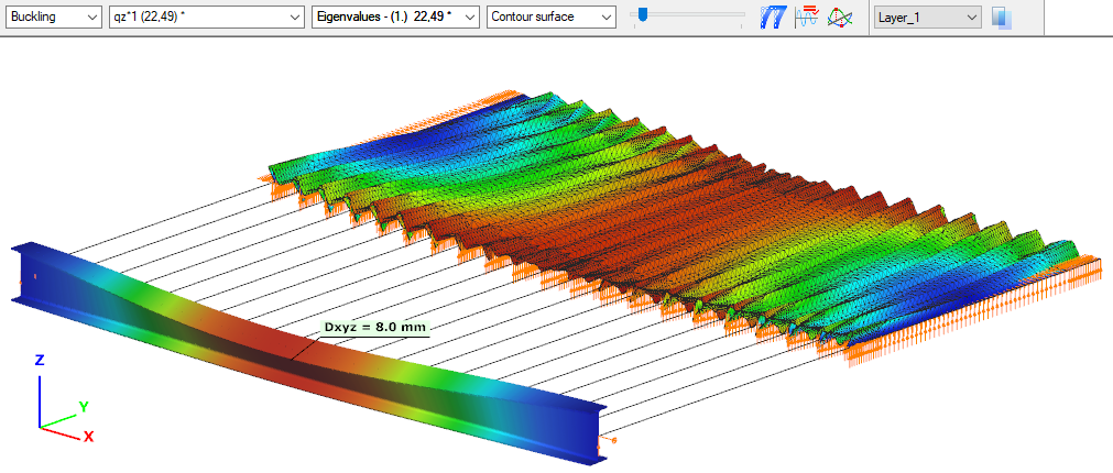
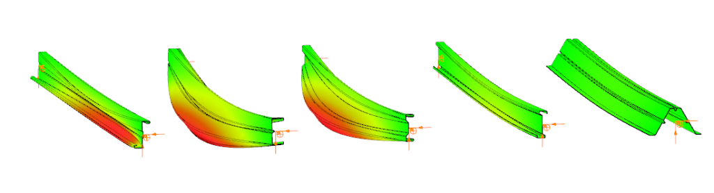
Did you know that you could use Consteel to perform local and distortional buckling checks for cold-formed members?
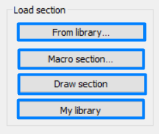
First, sections must be loaded into the model. To load cold-formed sections, you can choose from four options: From library, Macro section, Draw section, or My library.
After the first-order and buckling analyses are completed, you can proceed to the Ultimate limit state check settings and enable the steel design cross-section and buckling checks. At the bottom of the steel design section, there is an option to Consider the supplementary rules from EN 1993-1-3 for the design of cold-formed sections. This checkbox must be selected if you want to design cold-formed sections.
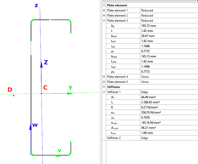
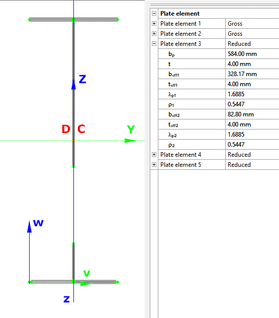
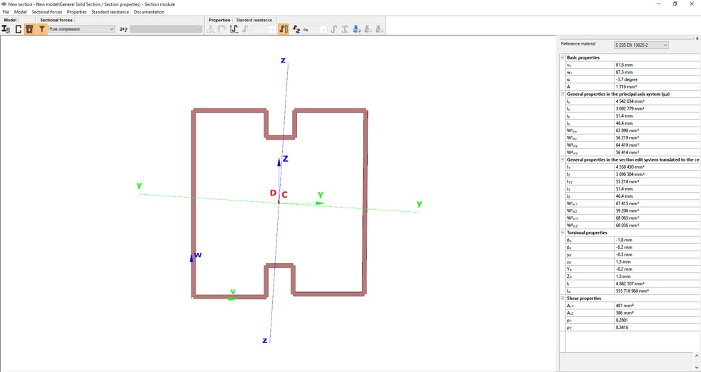
When the calculation is finished, by opening the Section module, we can review all the properties of the Effective section of the elastic plate segment model. By opening each plate element, we can verify the length, effective length, thickness, effective thickness, slenderness, and reduction factor separately. In addition, the properties of the stiffeners can also be verified: area, moment of inertia, lateral spring stiffness, critical stress, reduction factor, compressive stress, reduced effective area, and reduced thickness.
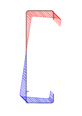
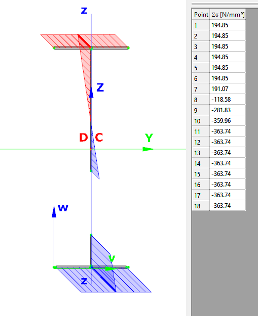
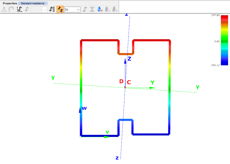
Similarly, the stresses can also be checked from the Properties tab. In the colored figure or diagram view, all the calculated stresses can be seen together with their resultants.
Consteel automatically takes into account the effect of distortional buckling when calculating the effective sections of cold-formed thin-walled sections.
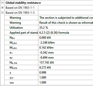
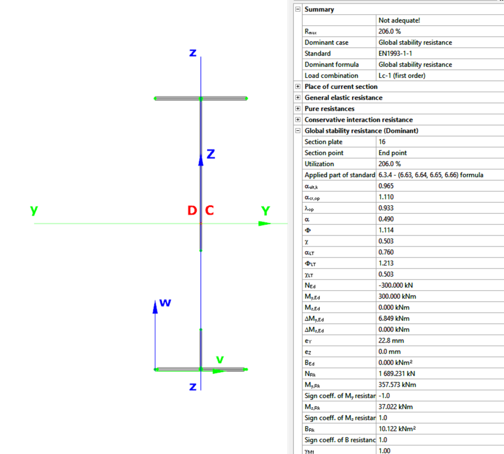
Moving on to the Standard resistance tab in the Section module, all calculated results can be verified, not only the dominant one. By opening the Global stability resistance check, we can see that, since we enabled the option to consider the supplementary rules from EN 1993-1-3 for the design of cold-formed sections, results are available both according to EN 1993-1-1 and according to EN 1993-1-3.
Download the example model and try it!
Download modelIf you haven’t tried Consteel yet, request a trial for free!
Try Consteel for freeDid you know that you could use Consteel to calculate effective cross-section properties for Class 4 sections?
Download the example model and try it!
Download modelIf you haven’t tried Consteel yet, request a trial for free!
Try Consteel for free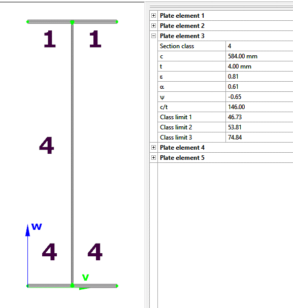
Bevezető
Szabályok segítségével történő teherkombináció szűrés esetén a leggyakrabban használt kihasználtsági típus az Acél – mértékadó vizsgálat. Milyen eredményeket vesz figyelembe pontosan ez az opció és mit jelentenek a hozzá kapcsolódóan választható korlátok?
A teherkombinációk szűrésének négy módja van: határállapotok, teheresetek alapján, kézzel vagy szabályok alkalmazásával. A három másik módszerrel ellentétben a szabályok szerinti szűrés kizárólag számítási eredmények alapján lehetséges.
A teherkombinációk számának csökkentésének leghatékonyabb módja minden bizonnyal a kihasználtsági szabályok alkalmazása.
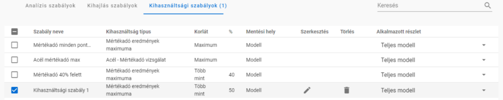
Kihasználtsági szabályok segítségével a teherkombinációkat az általuk okozott kihasználtságok alapján választjuk ki. A kihasználtságok a különböző tervezési vizsgálatokban elérhetők, mértékadó eredményekből és acél szelvények esetén az egyes vizsgálatokból is, úgy mint általános rugalmas szilárdsági ellenállás, tiszta igénybevételi ellenállások, interakció és globális stabilitás vizsgálat.

A mértékadó vizsgálat jelentése
A mértékadó vizsgálat nem mindig az a vizsgálat, amelyik a legnagyobb kihasználtságot adja, hanem az, amelyik a legnagyobb RELEVÁNS kihasználtságot. Tipikus példa erre, amikor a képlékeny interakciós képletek érvényesek, akkor ez lesz a mértékadó vizsgálat az általános rugalmassal szemben, jóllehet ez utóbbi magasabb kihasználtságokat ad.
Acél – Mértékadó vizsgálat
Az Acél – Mértékadó vizsgálat opció minden végeselem ponthoz tartalmazza a mértékadó vizsgálatból származó kihasználtságot minden kombinációban. Ez azt jelenti, hogy pontonként annyi kihasználtsági értékünk lesz, ahogy teherkombinációt kiszámoltunk.
Fontos megérteni a különbséget a Mértékadó eredmények maximuma és az Acél – Mértékadó vizsgálat opció között. A Mértékadó eredmények maximuma opció a mértékadó teherkombináció mértékadó vizsgálatból származó kihasználtságot tartalmazza minden pontban, mintegy burkolója az Acél – Mértékadó vizsgálat eredményeinek. Vagyis itt minden végeselem ponthoz egyetlen kihasználtság (és egy teherkombináció) tartozik. Egyben megegyezik a Globális vizsgálatok fülön megjelenő mértékadó eredmények táblázattal.
Amikor egy szabályt alkalmazunk, a kiválasztott kihasználtsági típushoz tartozó kihasználtságokat összevetjük a megadott korláttal. Azok a teherkombinációk, amelyekből származó eredmények megfelelnek a korlátnak, kiválasztásra kerülnek. A vizsgálat a választott modell részlet minden végeselem pontjában megtörténik.
Korlátok Acél – Mértékadó vizsgálat opció esetén
- Maximum: azon kombinációk kiválasztására, amelyek bárhol a legnagyobb kihasználtságot okozzák. Lehet ugyanaz, mint a Mértékadó eredmények maximuma, kivéve amikor vannak olyan kombinációk, ahol a kihasználtság ugyanannyi, és az a mértékadó. Ilyenkor itt az összes ilyen teherkombináció kiválasztásra kerül, míg a Mértékadó eredmények maximuma opciónál mindig csak egy mértékadó van.
- Több mint a legnagyobb érték %-a: ugyanazokat a kombinációkat választja ki, mint a Maximum és még azokat, amelyek az adott pontbeli legnagyobb kihasználtság adott százaléka feletti kihasználtságot eredményeznek. Például ha egy adott pontban a mértékadó kihasználtság 80%, a kihasználtsági szabály korlátja pedig ‘Több mint a legnagyobb érték 90%-a’, akkor ez a szabály ki fogja választani az összes olyan teherkombinációt, ami ebben a pontban 0,9*80%=72% és 80% közötti kihasználtságot eredményez.
- Több mint: kiválasztja azokat a teherkombinációkat, amelyek bárhol a megadott érték feletti kihasználtságot eredményeznek.
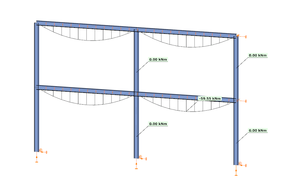
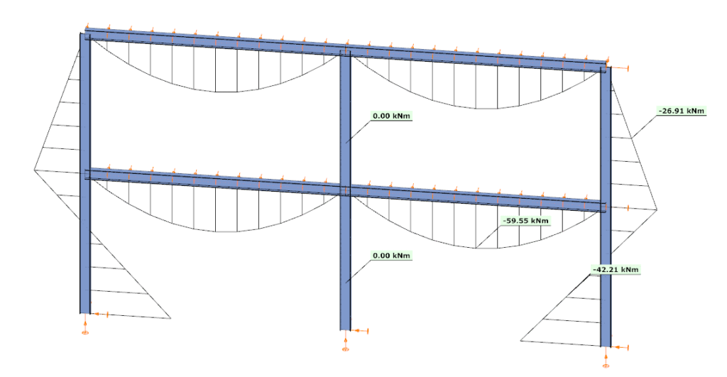
Nézzünk egy egyszerű síkbeli keretet példaként a jobb érthetőség kedvéért. A jobb oldali gerendát egy részletbe raktuk, amire három kihasználtsági szabályt alkalmaztunk. Öt pontot a bemutatás kedvéért kiválasztottunk, de természetesen a részletmodell minden pontja figyelembe van véve a szűrésnél.

Did you know that you could use Consteel to Consider the shear stiffness of a steel deck as stabilization for steel members?
Download the example model and try it!
Download modelIf you haven’t tried Consteel yet, request a trial for free!
Try Consteel for free
Did you know that you could use Consteel to draw a user-defined cross section and calculate its section properties?
In our previous article, we showed how predefined macro geometries make modelling fast and efficient. Later, we demonstrated how Consteel evaluates local and distortional buckling according to EN 1993-1-3.
This article focuses on the most flexible solution within this workflow: creating your own cross-section from scratch using the Section drafter module.
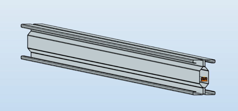
For line member modelling, the cross-section must first be loaded into the model. Besides using standard library profiles or macro sections, you can also choose the Draw Section option. This function is especially useful when a special geometry is required that cannot be reproduced with predefined macros, for example manufacturer-specific shapes, research sections, welded thin-walled members, or prototype geometries.
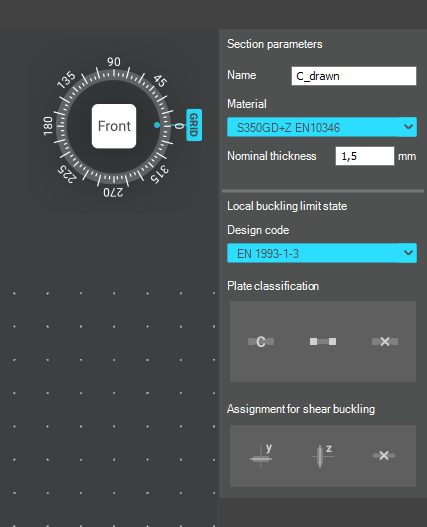
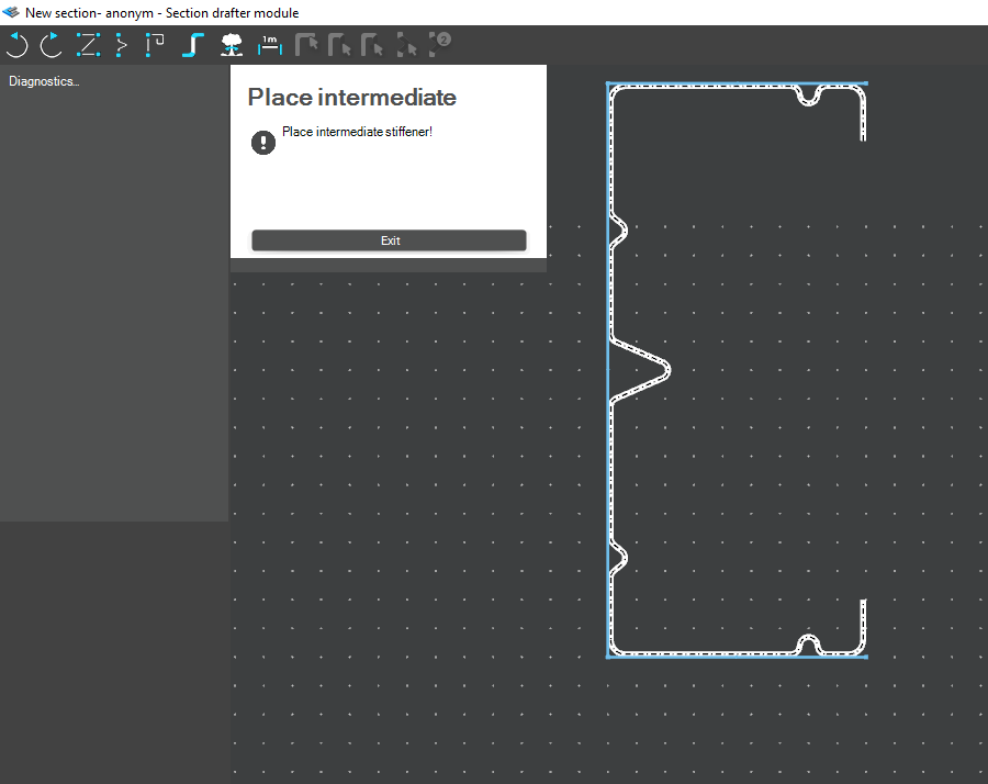
The Section drafter can be started from the Section Administration dialog by pressing the Draw section button. After launching the function, you need to select the section type, material quality and assign a name.
Two types of cross-sections are available: Cold formed section and General thin-walled section. This selection is not only geometric but also analytical.
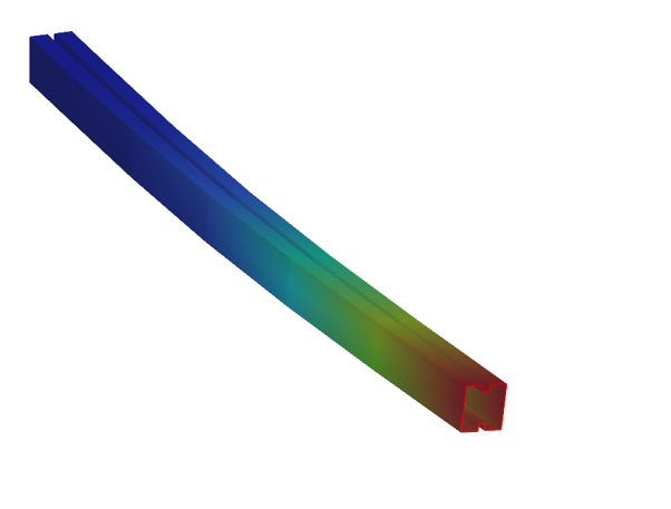
Cold-formed sections are drawn with a single reference line and uniform thickness. During the calculation, Consteel automatically considers distortional buckling effects according to EN 1993-1-3. These sections can later be used in purlin line objects if they are defined as Z- or C-like shapes.
General thin-walled sections allow different thicknesses along the contour and closed geometries. They are typically used for welded or fabricated sheet sections. In this case, strength, local and global stability checks are available, but distortional buckling evaluation is not included.
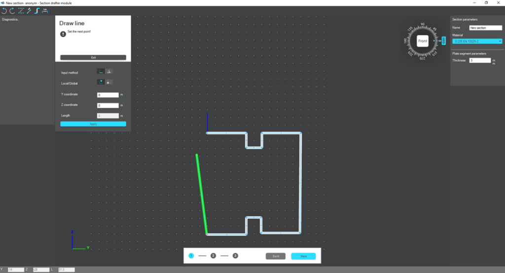
The drawing environment provides full control over geometry. Plate segments can be defined by coordinate input or by graphical selection. Cartesian or polar coordinates can be used, in local or global systems. Roundings are generated automatically between segments and can be modified later. The nominal thickness is also specified at this stage.
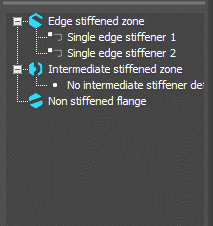
For cold-formed sections, stiffeners can be inserted using predefined macros, making it easier to model edge or intermediate stiffeners. However, these become structurally effective only after they are properly defined in the final phase of the section creation process.
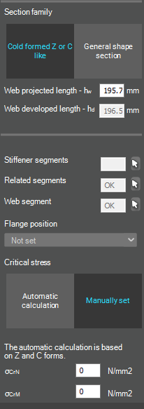
Once the geometry is complete, the required design parameters must be specified. For cold-formed sections, this includes the manufacturing type, thickness tolerance category and buckling curves. These inputs influence the calculated design wall thickness and stability verification. In the next step, the program evaluates the classification of each plate segment and determines the effective widths used in resistance calculations.
If stiffeners are present, they must be defined explicitly. When the section is identified as Z- or C-like, Consteel can automatically determine the critical stress of the stiffeners in accordance with EN 1993-1-3. This ensures that distortional buckling and stiffener interaction are properly considered during design.
After saving the section, it can be assigned to line members just like any library or macro profile. Following structural analysis, steel design checks can be performed. As shown in our article on buckling checks, the Section module allows detailed review of effective cross-sectional properties, reduction factors, slenderness values and stiffener behaviour. Consteel automatically accounts for distortional buckling when the supplementary rules of EN 1993-1-3 are enabled.
By combining library, macro, and user-defined sections, Consteel provides a complete workflow: fast modelling with macros, precise verification through buckling checks, and full flexibility with custom cross-sections.
Download the example model and try it!
Download modelIf you haven’t tried Consteel yet, request a trial for free!
Try Consteel for freeDid you know that you could use Consteel to include in your model a wide range of cold-formed macro sections?
For line member modelling, the cross-section must first be loaded into the model. In Consteel, there are four options to do this, either starting from the Section Administrator or directly during beam or column modelling: From Library, Macro Section, Draw Section, or My Library.
Cold-formed sections can be created using any of these four methods. Standard cold-formed cross-sections can simply be selected from the library. However, if a special cold-formed section is needed, it can be created via Macro Sections, including: RHS, CHS, L profile, Z shape, C shape, Sigma section, Zeta section, Hat section with stiffeners, double C section, double Sigma section, and double user-defined sections.
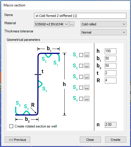
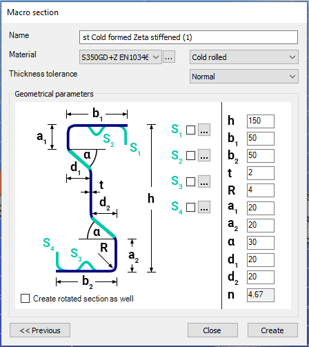
Macro sections are easy to create because the essential geometric characteristics are predefined, and the parameters can be modified intuitively. It is also possible to add profile stiffeners. Flange and web stiffeners can be configured in various forms, including single and double options. These defined stiffeners are included in the structural evaluation of distortional buckling, according to EN 1993-1-3.
The thickness tolerance category must be specified. This determines the design wall thickness for the section. In practice, macros follow the commonly applied tolerance categories used for coated steel sheet products.
If you want to use a double section, make sure to load into the model first the section that you want to duplicate.
For very special or unique sections, the Draw Section function can be used. This allows users to create fully custom cross-sections when standard or macro shapes are insufficient, by manually sketching the geometry.
Sections can be defined as cold-formed or general thin-walled, which determines how they are analyzed: cold-formed sections have uniform thickness and account for distortional buckling, while general thin-walled sections allow varied thicknesses and closed shapes, typically for welded or fabricated profiles.
This approach is especially useful for modelling unique shapes, prototypes, or as-built sections, giving full control over every segment to accurately capture geometries that standard libraries or macros cannot reproduce.
Download the example model and try it!
Download modelIf you haven’t tried Consteel yet, request a trial for free!
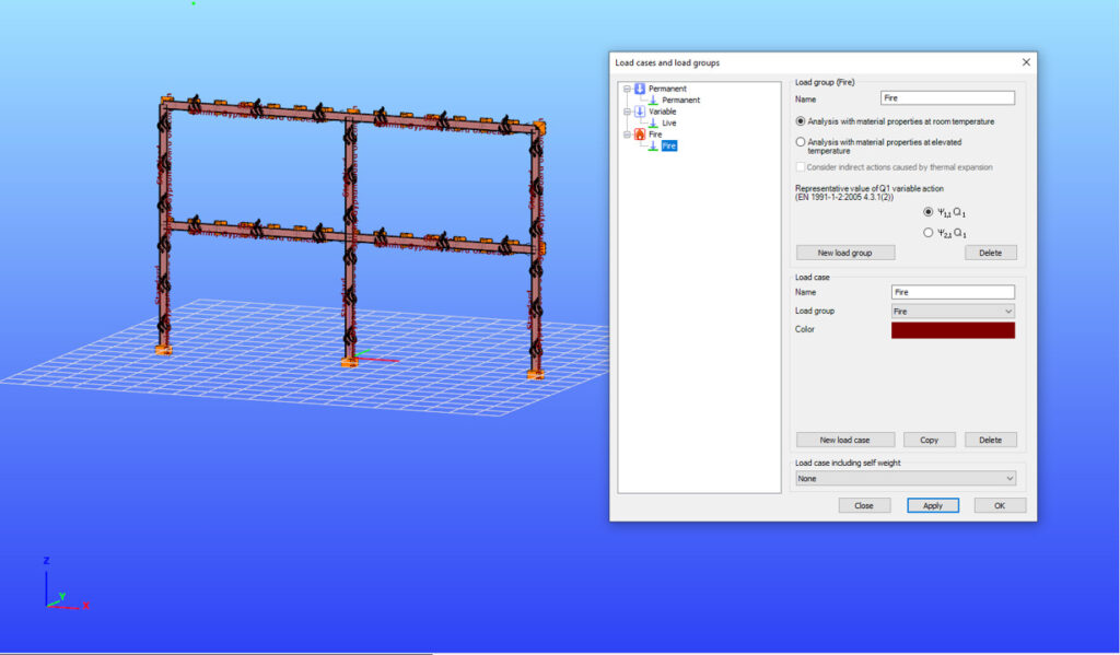
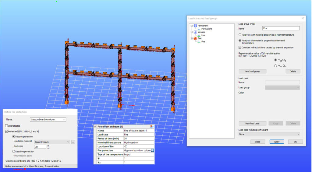
Try Consteel for freeDid you know that you could use Consteel to perform structural analysis at room and elevated temperatures as part of design process for fire resistance?
Download the example model and try it!
Download modelsIf you haven’t tried Consteel yet, request a trial for free!
A Consteel lehetőségek széles skáláját kínálja a teherkombinációk szűréséhez, amely határállapot, tehereset, valamint analízis eredmények és kihasználtságok alapján is történhet. Szűrők különböző kombinációinak alkalmazásával a tervezési folyamat tudatosabbá válhat és csökkenhet a számítási idő.
Szűrési lehetőségek
A szűrést a Teherkombináció csomag megadása nevű dialóg on lehet elvégezni.
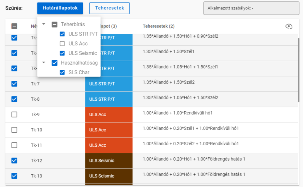
A határállapotok és teheresetek szerinti szűrést az azonos nevű gombok alatt lenyíló jelölőnégyzetekkel lehet végrehajtani.
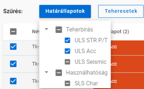
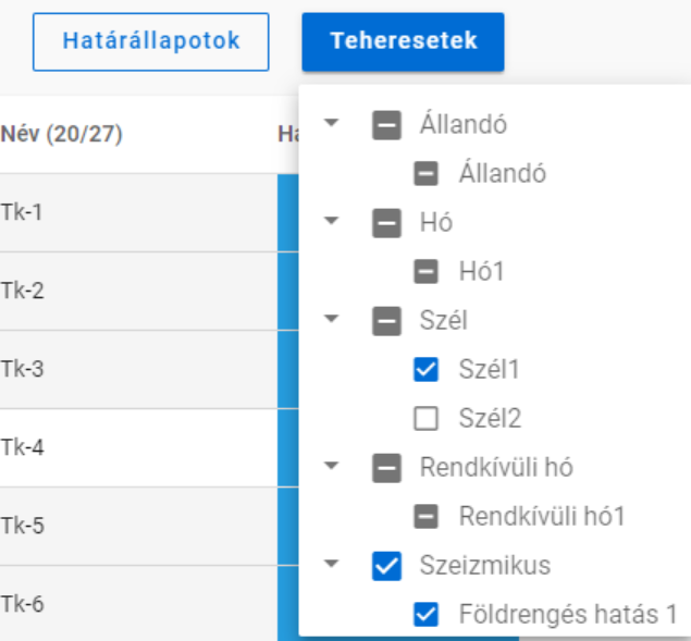
A jelölőnégyzeteknek három állása van. Nem csak kiválasztásra használhatóak, hanem egyben az adott teherkombináció csomag tartalmát is mutatják. Kézzel csak bepipált vagy üres állapotra kapcsolhatók, a köztes állás akkor jelenik meg, ha egyéb szűrőket alkalmazunk.
A határállapotok és teheresetek szerinti szűrést számítási eredmények nélkül is lehet alkalmazni.
A szabályok szerinti szűrés viszont minden esetben analízis vagy tervezési eredményeken alapszik. A különböző típusú szabályokat egyszerre vagy egymás után is lehet alkalmazni, hogy kiválasszuk a kívánt teherkombinációkat.
Amikor egy szabályt alkalmazunk, a filter megvizsgál minden teherkombinációt, ami ki volt választva a Teherkombináció csomag megadása ablakban -akár kézzel, akár határállapota vagy a benne lévő tehereset alapján-, minden olyan végeselem pontban, amit a szabály megkíván. Azok a teherkombinációk, amik megfelelnek a szabálynak, kiválasztva maradnak, míg azok, amelyek nem, nem lesznek többé kijelölve.
- Analízis szabály alkalmazásával deformációk vagy igénybevételek alapján választhatunk ki kombinációkat. Az analízis eredményeket a szabály megadásától függően minden végeselem pontban vagy csak az elemvégeken vizsgáljuk (pl. kapcsolatokhoz). Deformációkat csak SLS, míg igénybevételeket csak ULS kombinációkban vizsgálunk.
- Kihajlás szabállyal azok a teherkombinációk választhatók ki, amelyekhez tartozó rugalmas kritikus teherszorzó (első kihajlási sajátérték) kisebb a megadott értéknél.
- Kihasználtsági szabállyal a teherkombinációkat a kiválasztott részletmodell minden végeselem pontjában meghatározott kihasználtságok alapján lehet szűrni. Acél elemek esetén a kihasználtságok elérhetők minden szabványos vizsgálatból, mint pl. általános rugalmas szilárdsági ellenállás, tiszta igénybevételi ellenállás, interakciók és globális stabilitásvizsgálat. A filter csak ULS kombinációkra alkalmazható.
Különböző típusú szűrők kombinálása
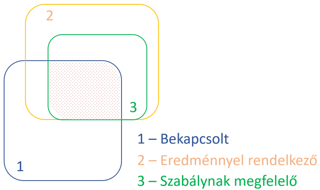
A háromféle szűrőt lehetséges és érdemes együtt használni, azonban fontos tudni, hogy a szabályok szerinti szűrést csak azokon a kombinációkból válogat, amik ki vannak választva és van hozzájuk megfelelő számítási eredmény.
Vegyünk egy példát!
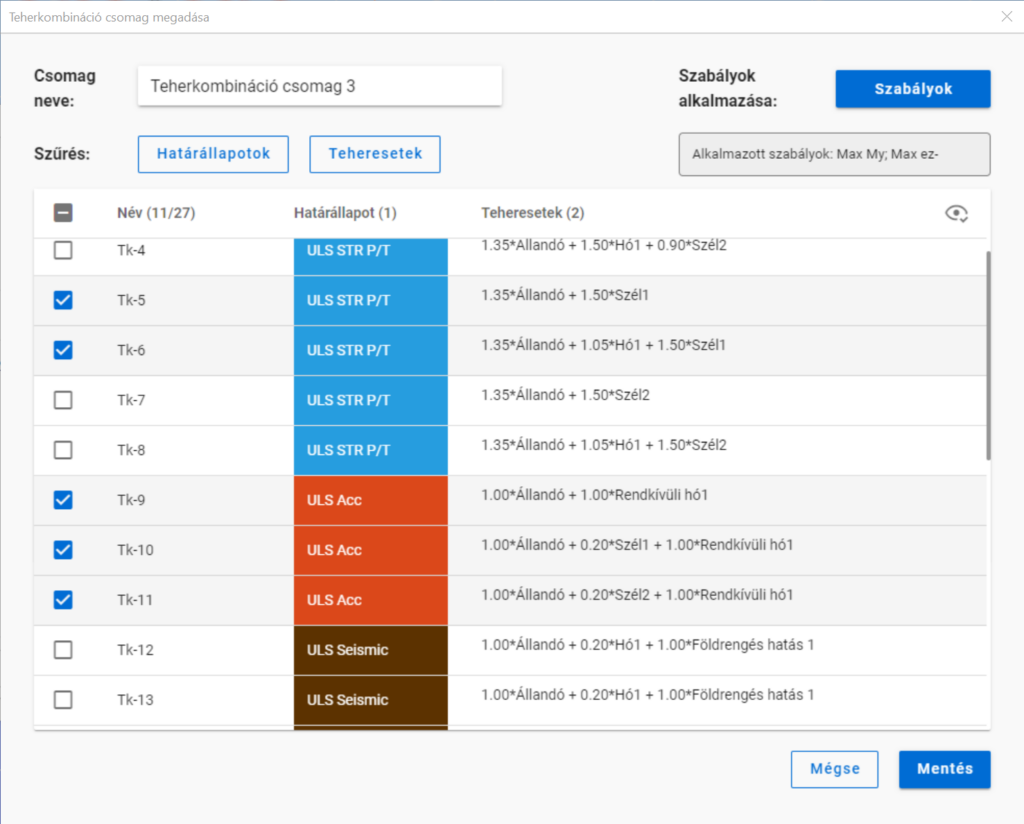
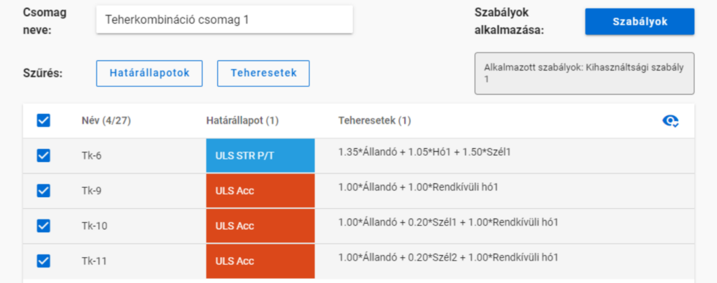
Egy egyszerű síkbeli keretmodell, amiben 27 teherkombinációt generáltunk többféle határállapotban. Az analízis és szabványos tervezési eredmények rendelkezésre állnak az összes teherkombinációban.
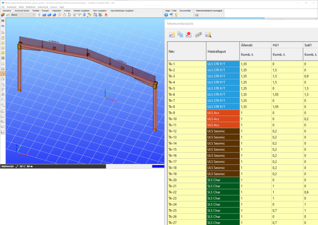
Alkalmazzunk egy kihasználtsági szabályt, amely kiválasztja azokat a teherkombinációkat, ahol a legnagyobb mértékadó kihasználtság 50% felett van.
Ekkor négy teherkombinációt kapunk:
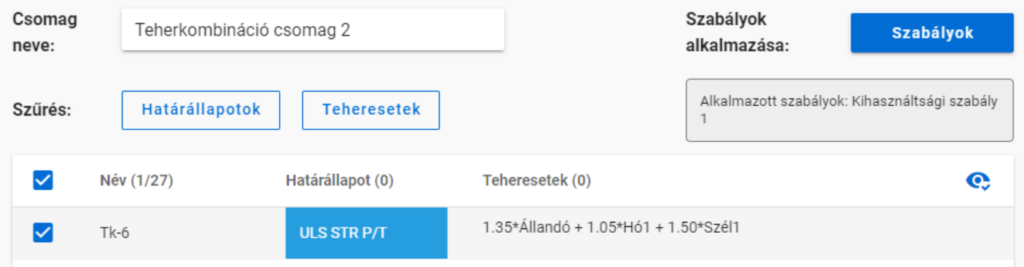
De ha az 50%-os szabály alkalmazása előtt kikapcsoljuk a rendkívüli teherkombinációkat,
akkor a szabály alkamazása után már csak egy kombinációnk marad.
Több szabály alkalmazása
Több szabály együttes alkalmazása esetén a létrejövő teherkombináció-lista azoknak a listáknak az összege lesz, amik a szabály külön-külön való alkalmazása esetén jöttek volna létre.
gate