Part 1: Buckling utilization differences
The Eurocode EN 1993-1-1 offers basically two methods for the buckling verification of members:
(1) based on buckling reduction factors (buckling curves) and
(2) based on equivalent geometrical imperfections.
This article reviews how these two methods relate to each other in terms of the final member utilization. For the sake of simplicity, we consider only members subjected to pure compression, undergoing flexural-buckling. For case (1) the chapter 6.3.1 is used while for case (2) the imperfections are considered to take the shape of a buckling mode and the corresponding chapter is the 5.3.2 (11).
It is an obvious expectation that these two standard procedures should yield the same utilization for the same problem. However, this is by far not the case in general.
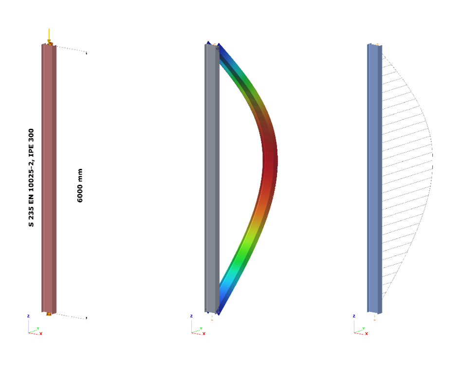
Let’s see the following simple example of a simply supported, compressed column with a Class 2 cross-section (plastic resistance calculation allowed). The column is 6 meters high and has an IPE300 cross-section made of S235 steel. The standard amplitude for the buckling mode based imperfection is calculated by Eq. 5.9-5.11, that is equal to v0 = 13.4 mm. The next figure shows the model, the buckling mode shape – which is a classic flexural buckling about the weak axis – and the second order weak axis bending moment distribution.
- Important to note that the verification based on equivalent geometrical imperfection should be calculated from the results of a second order analysis using the linear cross section check defined by Eq. 6.2 (or Eq. 6.1 for elastic cases).
The most utilized cross-section will be the middle one, where the second order bending moment value depends naturally on the level of compressive force according to the well-known amplification relationship:
$$M_{zII}=N_{c,Ed}*v_0*\frac1{1-\frac{N_{cr}}{N_{c,Ed}}}$$
where is the applied compressive force, Nc,Ed is the amplitude of the equivalent geometrical imperfection and 1/(1-(Ncr/Nc,Ed)) is the amplification factor depending on the elastic critical load Ncr = 347,6 kN (Euler load). The utilization of this critical cross-section can be calculated according to Eq. (6.2):
$$U^{IMP}_{max}=\frac{N_{c,Ed}}{N_{Rd}} +\frac{M_{z,II}}{M_{z,Rd}} =N_{c,Ed} \Bigg[\frac{1}{N_{Rd}} +\frac{1}{M_{z,Rd}} *v_0*\frac1{1-\frac{N_{cr}}{N_{c,Ed}}}\Bigg]$$
Figure 2. shows the relationship between the applied compressive force and the second order bending moment and utilization of the middle cross-section where NRd = 1264,6 kN and Mz,Rd = 29,28 kNm. It can be clearly seen that the utilization is nonlinearly depends on the compressive force level due to the nonlinearity of the second order bending moment. The utilization corresponding to the 100% value gives the buckling resistance of the column:
GateIntroduction
In case of a model with a lot of load cases (wind in different directions, with and without internal pressure, snow,seismic etc.), hundreds of load combinations can be generated acc. to EC but many of these combinations are irrelevant. Running an Analysis on all of the load combinations can take a lot of time, that could be saved, if the relevant load combinations are calculated only.
How to do that
- To find the relevant load combinations and save calculation time: At first perform only elastic first order analysis and global checks based on that. Even first order calculation can take much time if there are non-linear elements (practically tension-only rods) in the model. It is possible to temporarily change the non-linear elements to linear ones in order to let Consteel calculate the load combination analysis results with superposition of the load cases which is much quicker than calculation with non-linear elements.
- Under the Global checks tab, on the results table, selection of the load combinations with significant utilization can be done. (As on all tables in Consteel, multiple selection of different load combinations can be performed easily using Ctrl+select, or Shift+select features of Windows) With a right click on the selected combinations, use Select only these combination for the Analysis function to apply your choice to the next run.
The main objective of the research paper is to present the technical and economical results obtained for standardized structures with small and medium spans. The obtained results can represent a starting point for designers as well as for investors, who intend to build single storey steel structures. According to the research, there have been identified a series of interrelated factors which may represent sources of savings in the optimization process. The authors highlight the work strategy in creating standardized structural systems that will improve product performances. The paper analyzes three standardized configurations including the following structural solutions: frame structures made of hot rolled beams and columns, thin-walled frame structures and structures using trusses and rectangular hollow sections columns. All configurations have been analyzed using Consteel 7.0 design software, for Bucharest region, loads evaluation being performed according to the current standards. Free height of the building varies between 4.00m and 6.00m, bay between
4.00m and 5.00m, and the span between 8.00m and 12.00m. The article presents the principle of the structural configurations and gives reference charts in order to estimate the steel consumption per square meter, aiming structural performance in what concerns price per square meter and execution time.
Click the button bellow to download and read the full article. (ROU)
gateNowe trendy w normach: EUROKOD 3 – efektywne globalne projektowanie konstrukcji.
Kliknij przycisk poniżej, aby pobrać i przeczytać cały artykuł.
gateNowe trendy w normach EUROKOD 3 – efektywne globalne projektowanie konstrukcyjne Analiza oparta na modelu 3D przy użyciu ogólnej metody elementów skończonych belkowo-słupowych.
Kliknij przycisk poniżej, aby pobrać i przeczytać cały artykuł.
gateThe case study exposes a practical evaluation of fire resistance of an old structure of a Spanish industrial building composed of steel built-up members; the truss members are angles connected through packing plates and the columns are battened chords. A simple calculation model was used element by element. First, heat is transferred to individual steel elements by convection and radiation in thermal study. The contributions of these two modes of heat transfer were treated by a practical approach. In mechanical study, the second order analysis was used with global imperfections. Finally, the fire resistance was evaluated R15 after some proposals.
Click the button bellow to download and read the full article.
gateThe paper presents the influence of the diaphragm effect on the behavior of pitched roof portal frames, having Z purlins and corrugated sheeting as cladding. The paper highlights the stabilizing effect in terms of αcr on portal frames by taking into account the lateral constraints ensured by a typical cladding system – Z purlins with one layer of sheeting panels. The purpose of the paper is to make a comparison between the simplified design model of a portal frame, where the supports simulating the purlins are considered with infinite axial rigidity and a portal frame design model where the calculated stiffness of the cladding for the lateral supports is introduced manually. The obtained results highlight the importance of the diaphragm effect and refer to the variation of the load multiplication factor αcr for main structural elements. The fundamental objective of this research is to develop a relatively fast checking procedure, easy to use in the current design process, by including the diaphragm stiffness in the analysis of the pitched roof portal frame. Using Abaqus, simplified calculation procedures are validated by complex FEM models.
Click the button bellow to download and read the full article.
gateA two-part paper has been written to summarise the main results of a comparative study on the design provisions currently adopted in Europe (EU) and the United States (US) for steel storage pallet racks. In part 1 (Discussion and general comparisons), key features of the verification procedures for thin-walled cold-formed members as well as of the design alternatives permitted by the EU and US rack codes have been discussed, pointing out the most relevant similarities and differences. The present part 2 applies six design alternatives to medium-rise pallet racks unbraced in the longitudinal direction. In particular, the proposed research outcomes are based on the design of 216 racks differing for configurations, geometry of components and degree of rotational stiffness of beam-to-column joints and base-plate connections. Results are presented and compared directly to each other in term of safety index in order to allow for a concrete appraisal of the most relevant differences between the considered design methods, highlighting also the influence associated with the approaches to modelling the geometric imperfection effects. Finally, Appendix A presents a complete design example to be used as benchmark for researchers and designers, where all the discussed design options are applied.
Click the button bellow to download and read the full paper.
gateClick the button bellow to download and read the full article at page 187-195.
In this paper a numerical study is presented which examines a steel frame with two different finite element programs. Stability failure is more frequent in a lot of cases than strength failure hence it is important to focus on these failure modes: global, in-plane-, out-of-plane -, lateral-torsional- and local buckling. Three models were used with different elements such as shell elements and 7 DOF beam elements. 7 DOF beam elements were used in the first model, shell elements were used in the other two. The first of the shell models gave too much local buckling shapes therefore it was improved with local constraints and that is the third model where global buckling shapes can be examined. There are three different procedures to calculate the resistance: (i) the general method, (ii) the method of the reduction factors, and (iii) the simulation. The analysis results of the different programs and design methods were compared to each other and to the manual calculation based on the Eurocode 3 standards.
gateThe new versions of the EN 1993-1-1 (EC3-1-1) and the EN 1993-1-5 (EC3-1-5) standards have introduced the general method designing beam-column structures; see [1] and [2]. The design method requires 3D geometric model and finite element analysis. In a series of papers we present this general design approach. The parts of the series are the following:
- Part 1: 3D model based analysis using general beam-column FEM
Click the button bellow to download and read the full article.
gate