Introduction
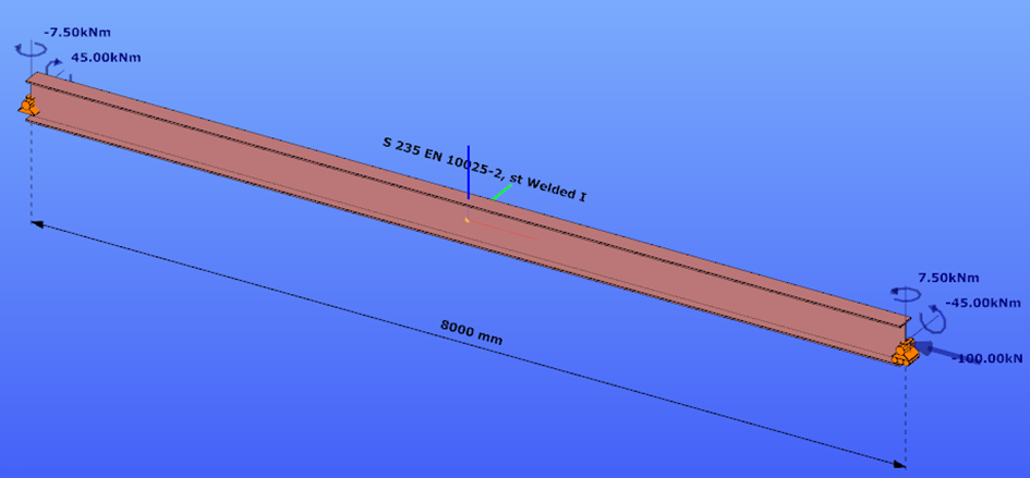
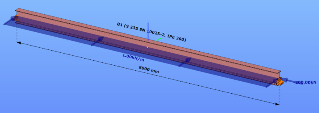
This verification example studies a simple fork supported beam member with welded section equivalent to IPE360 (flanges: 170-12,7; web: 347-8) subjected to biaxial bending due to concentrated end moments and compression due to axial force. Second order deformations of the middle cross-section of the member are calculated by hand and by the ConSteel software using both 7DOF beam and shell finite elements and Superbeam function. In addition to the verification, the difference between modelling with 6DOF and 7DOF elements is demonstrated.
Geometry
Calculation by hand
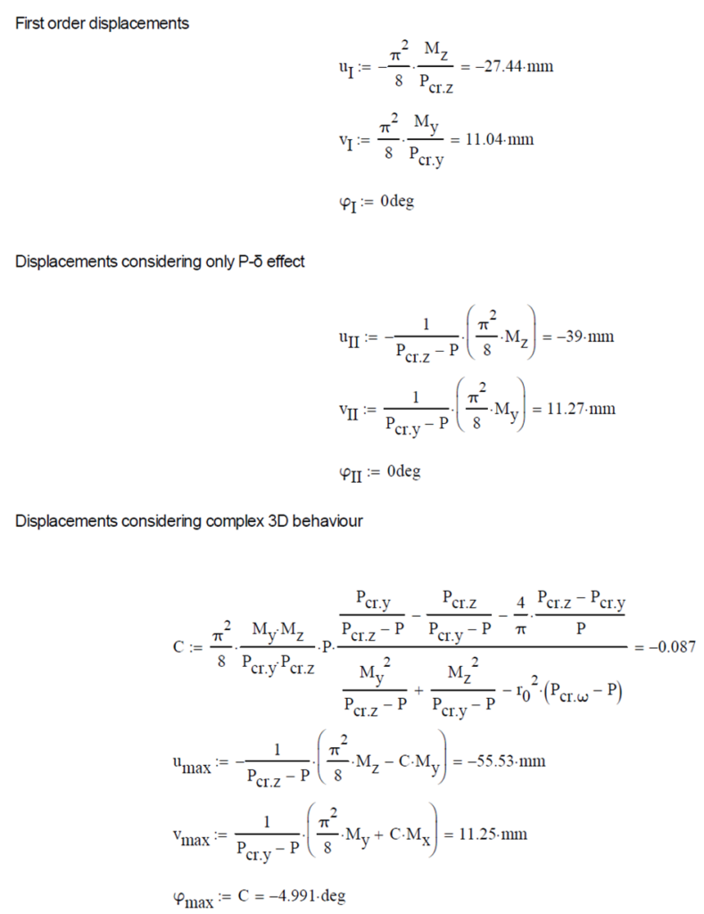
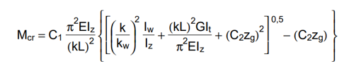
The first order and the simple amplified (P-δ) deformations can be analitically calculated by the well known formulas. The calculation of the second order deformations considering true, three-dimensional behaviour of the beam is however so complicated that there are only approximate analitical formulas available for hand calculation. The formula below can be found in Chen, W. and Atsuta, T.: Theory of Beam-Columns, Vol. 2: Space behavior and design, McGRAW-HILL 1977, p. 192

Computation by Consteel
Version nr: Consteel 15 build 1722
First order
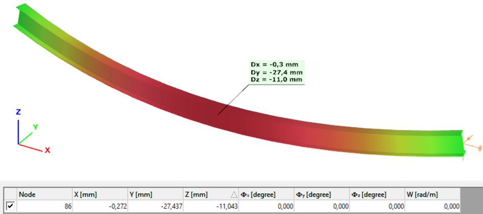
Second order – 6DOF beam element
The second order deformation of the member which was computed by the ConSteel software. It is visible that there is no torsion, only increments of the lateral displacements due to P-δ effect:
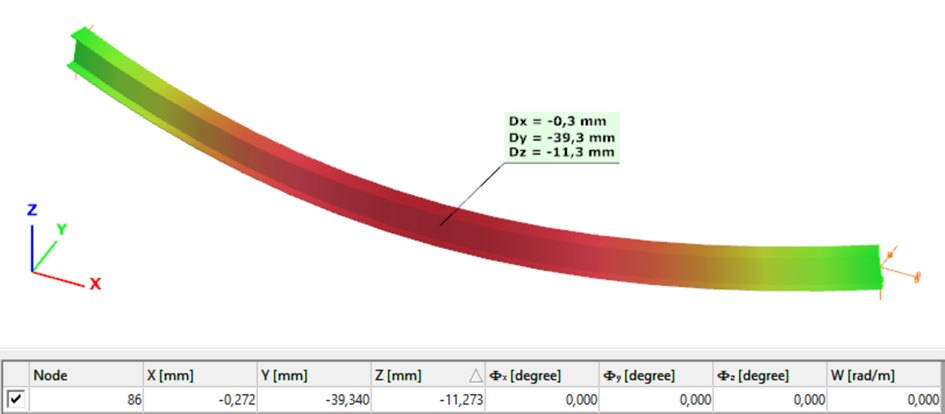
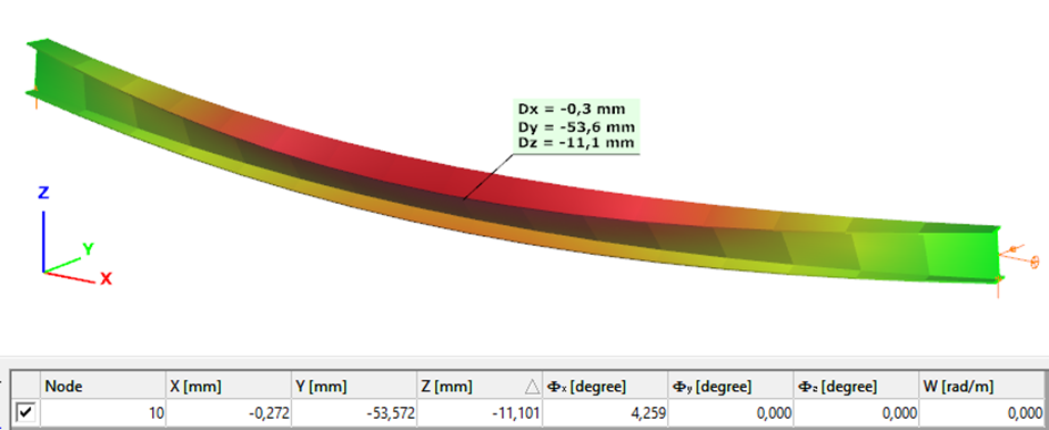
Second order – 7DOF beam element
The second order deformation of the member which was computed by the ConSteel software using the 7DOF beam finite element model (n=16). It is visible that there is torsion and further increment in the lateral displacement (Dy):
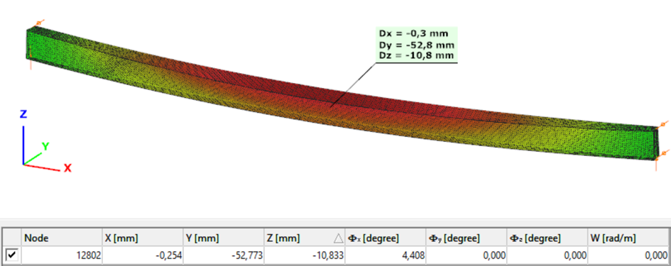
Second order – Shell finite element
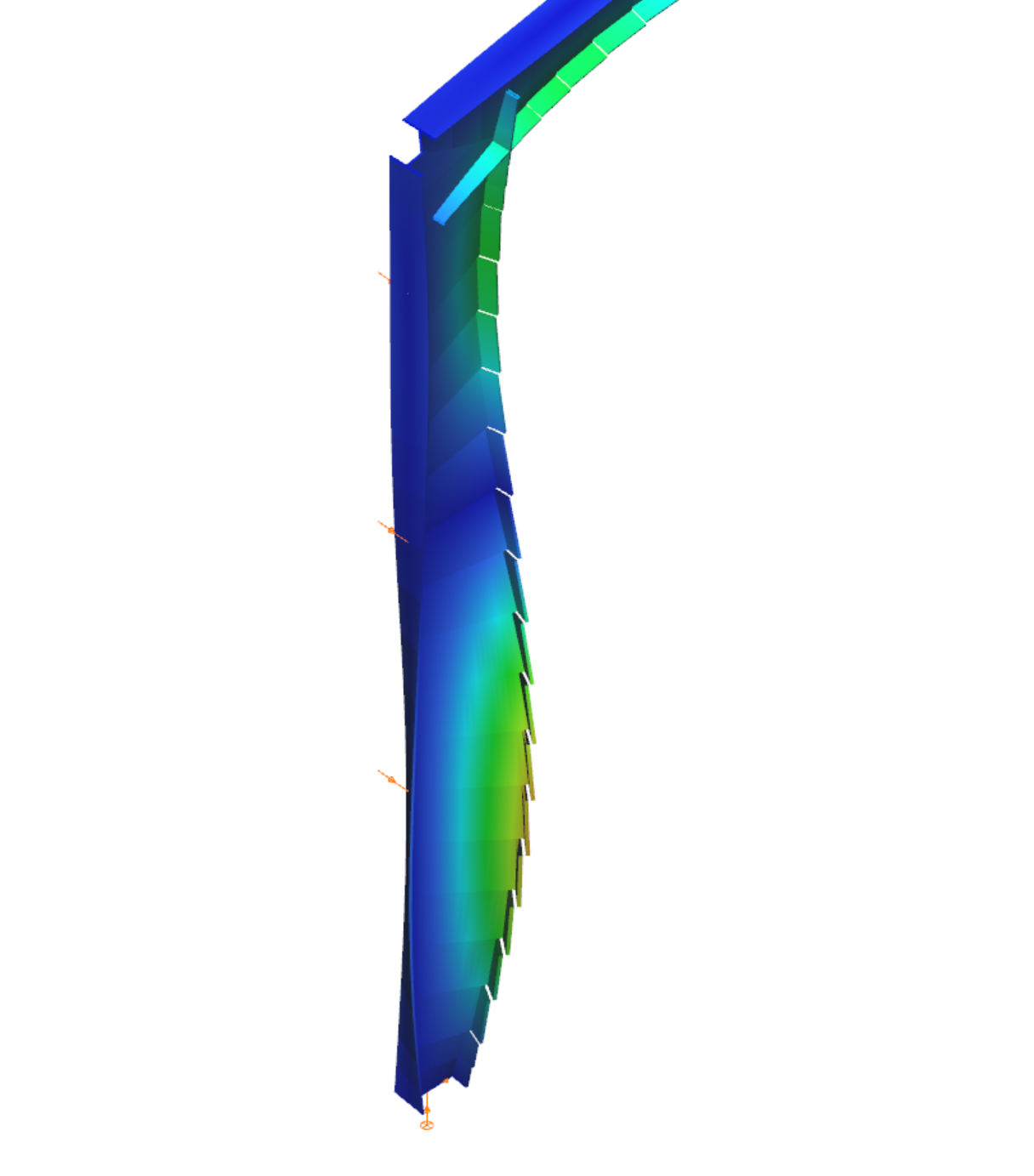
The second order deformation of the member which was computed by the ConSteel software using the shell finite element model (δ=25mm):
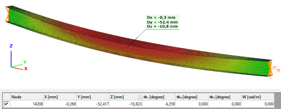
Second order – Superbeam
The second order deformation of the member which was computed by the ConSteel software using the Superbeam model (δ=25mm):
Introduction
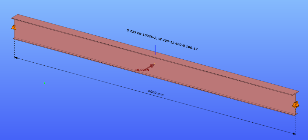
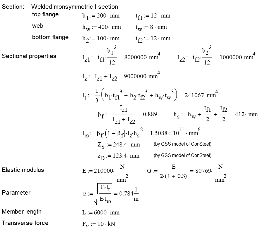
This verification example studies a simple fork supported beam member with IPE 360 section subjected to axial force and bending about the minor axis due to lateral, distributed force. The second order bending moment and the maximum axial compressive stress of the member is calculated by hand and by the Consteel software using the 7DOF beam finite elements.
Geometry
Calculation by hand

Computation by Consteel
Version nr: Consteel 15 build 1488
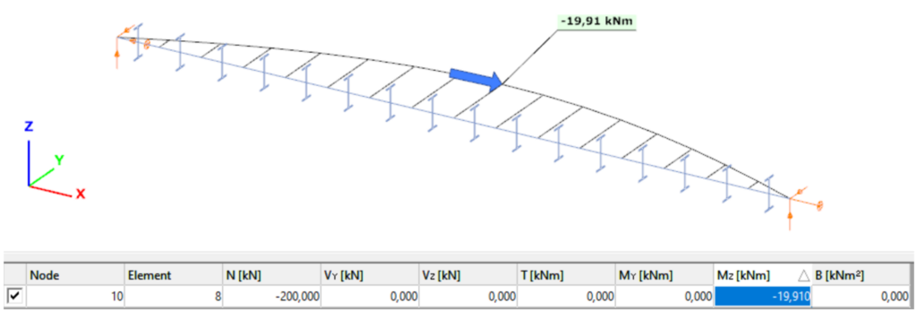
7DOF beam element The second order bending moment diagram of the member which was computed by the Consteel software using the 7DOF beam finite element model:
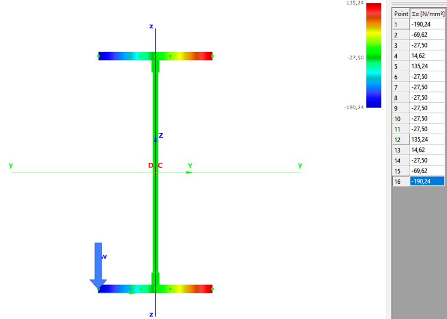
Normal stress in the middle cross-section:
Introduction
Our verification examples are created to be able to compare hand calculation results with Consteel anaysis results with using either 7DOF beam or shell finite elements. This example is a member of mono-symmetric I- section loaded with transverse concentrated load.
Geometry
Calculation by hand
Computation by Consteel
Version nr: Consteel 15 build 1488
- 7DOF beam element
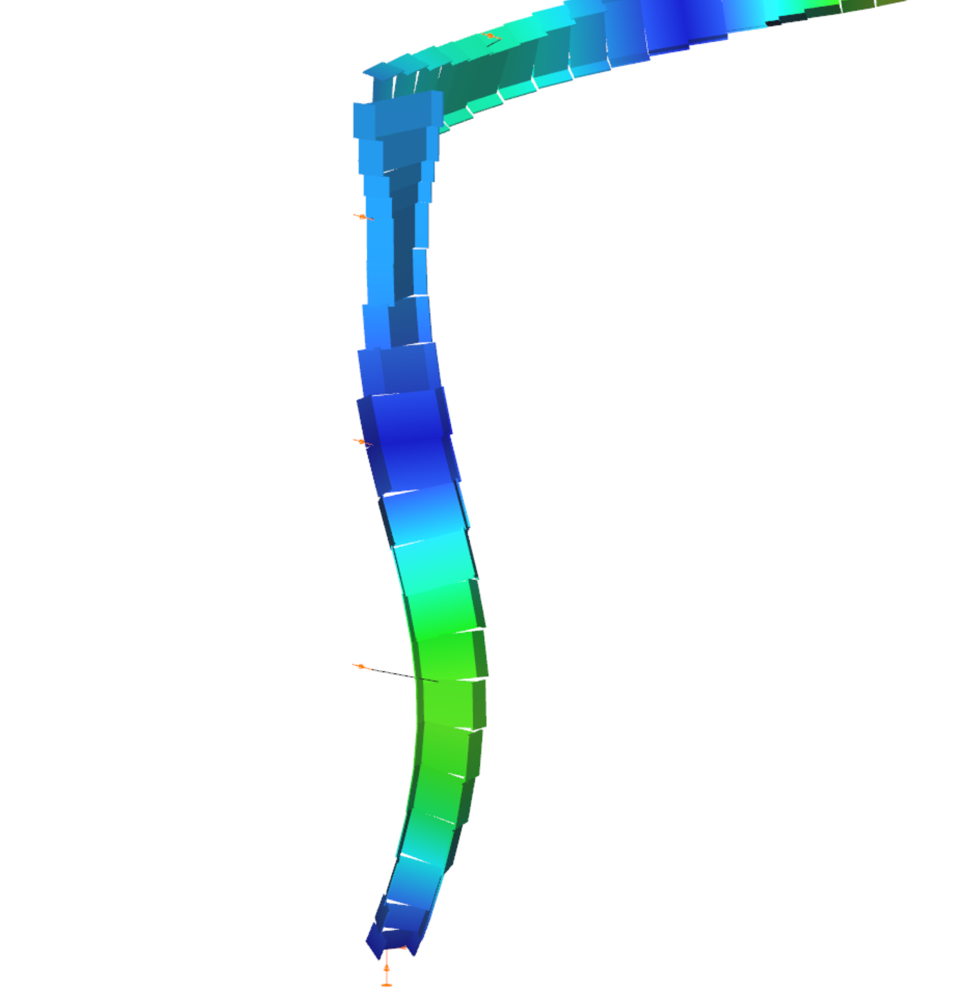
Deformation of the member with the numerical value of the maximum rotation (self-weight is neglected):
Introduction
Our verification examples are created to be able to compare hand calculation results with Consteel anaysis results with using either 7DOF beam or shell finite elements including Superbeam function. This example is a member in torsion loaded with concentrated torque.
Geometry
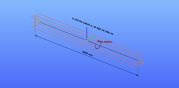
Calculation by hand


Computation by Consteel
Version nr: Consteel 15 build 1488
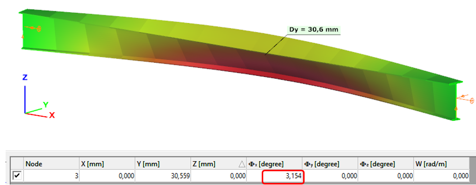
- 7DOF beam element
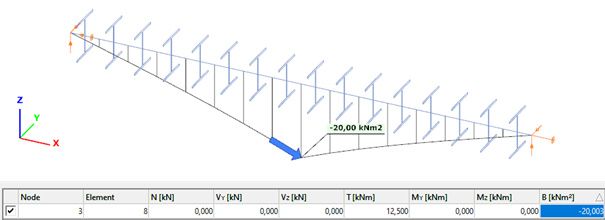
Deformation of the member due to concentrated twist moment:
Bimoment of the member due to concentrated twist moment:
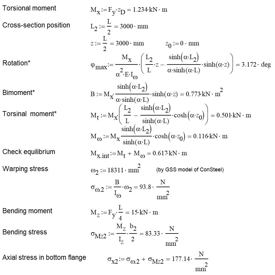
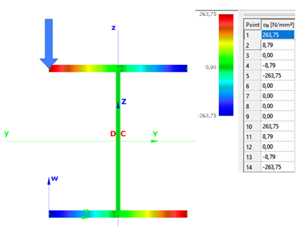
Warping normal stress in the middle cross-section:
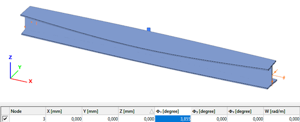
- Shell FE model
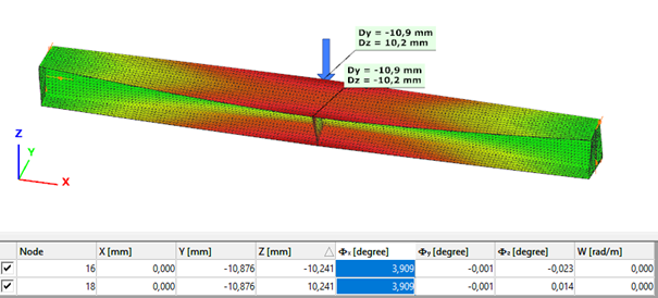
Maximum deformation of the middle cross-section:
Introduction
As it is important to have a clear overview of the structural model, the visualization of the analysis results is also essential when it comes to effective design process. From Consteel 15 we use an advanced method for deformation representation which makes it smooth and realistic.
Description
Civil engineering software in general use the traditional beam-type deformation representation where the section is shown on the deformation of the reference line. There are some consequences of this representation mode that can be disturbing for the users. The best example is an eccentric support, where the deformed shape is visualized as if the supported point would’ve moved. The reference line indeed moved but the supported point not – the representation can not show that.
With Consteel’s advanced deformation representation not only the position of the reference line points are calculated and the section is only shown automatically, but the positions of all the decorated points of the section are calculated during a post-process and so it is possible to represent the real deformations. As a consequence it is also visible that the supported points stay in position.
Introduction
During the lifetime of a steel structure changes often happen. These changes usually result an increase of loads acting on some of its elements which therefore may need to be strengthened.
Strengthening is usually done by welding additional steel plates to the existing members. In the case of I sections, usually, the flanges are reinforced to increase the bending moment capacity or the web is stiffened to avoid local buckling or crippling at support regions.
This paper will focus on the increase of bending moment capacity.
Lateral-torsional buckling resistance
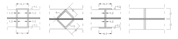
The usual practice is to either increase the compression flange thickness by adding additional plates to it, or by widening it with the help of angles, as can be seen in the pictures below.
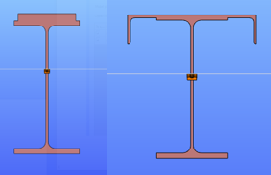
Although these can be very efficient ways to increase the bending moment capacity of a beam, welding on site is a complex process and might require the temporary removal of structural or non-structural elements connected to the flange of the beam. Welding especially “above the head” is difficult, the quality of weld seam needs to be properly checked.
Bending moment capacity of a beam might be limited by lateral-torsional buckling. If the section is not sufficiently restrained laterally against torsion, its actual load-bearing capacity will be lower than the value which depends purely on its section resistance.
In such cases, if the LTB behaviour could be directly improved, there would be no need to strengthen its cross-section along its full length. Here comes the Superbeam as a possible help.
Additional lateral restraining elements are often difficult to be added, therefore this is often not an option.
If we look at what LTB resistance of an I section depends on, we can see, that if we don’t want to change its cross section along its full length, it depends on the value of the reduction factor responsible to consider lateral-torsional buckling χLT.
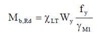
This reduction factor is calculated from the slenderness value of the beam, which needs to be improved (reduced) to result a lower, more favourable reduction factor.
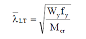
Without changing the cross section, the only way to do this is by improving the critical moment value. Increasing this value can be made not only by changing the cross-section but also by changing the boundary conditions.
The value of parameters ‘k’ and ‘kw’ depend on the boundary conditions, where ‘k’ means a factor which depends on how the section is fixed against weak axis bending at its ends and ‘kw’ means a factor which depends on how the section is fixed against warping. Warping is the phenomenon when the upper and lower flange of an I section twist in opposite directions.
To change the end conditions is typically difficult, but a certain limitation of the twist of flanges relative to each other ie. preventing or limiting warping might be possible. Limitation of this twist can be obtained by connecting the flanges by an additional element which has non-zero torsional stiffness. This torsional stiffness will prevent the counter-rotation of the flanges and therefore the warping and allowing to consider a ‘kw’ value different than 1.0 in this formula.
Consteel supports several such strengthening profiles and can determine the torsional stiffness to be considered in preventing or limiting warping.
Analysis with Consteel Superbeam
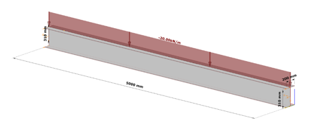
Let’s take the following case. We have a simple supported 5 m long beam loaded by a uniform load of 20 kN/m acting at the top flange, on top of its self weight, without any intermediate lateral support. Its section is a welded I profile, made of S235, 10 mm thick plates, flange width of 200 mm and total section depth of 320 mm.
As we can expect, in the case of such a large unbraced length, the bending moment resistance would be strongly limited by lateral-torsional buckling, and therefore we can expect that strengthening by the proposed method is viable.
The critical moment of this beam is obtained in Consteel using linear buckling analysis with 7DOF beam elements option of the Superbeam, which has found the critical multiplier of 2.88.
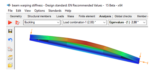
This results Mcr = 2.88*64.18=184,84 kNm and a slenderness λ of 1,036 and reduction factor of 0,519.
The final bending moment resistance is 103 kNm.
Let’s further assume that this resistance needs to be increased by 30% due to new requirements. Let’s see whether a successful strengthening without modifications of the cross-section would be possible.
gatePerfect the understanding of your structure with advanced buckling sensitivity results illustrated on proper mode shape and colored internal force diagrams.
gateCivil engineering software in general use the traditional beam-type deformation representation where the section is shown on the deformation of the reference line. In Consteel 15 we use an advanced method for deformation representation which makes it smooth and realistic. The analysis results are the same, but with the improved visualisation the real 3D behavior of the structure can be better seen.
gateHave you ever tried to visualize the stress distribution of a cross-section from the colored representation? To make it easier for you, we are now introducing Stress diagrams. Watch the video below to learn how to use this feature.
gateGood model and result visualization leads to better understanding and correct interpretation of any data model compared to texts or tables. With the help of Coloring by section feature, you will be able to switch to a new model view where the members get colours from their cross-section type. Watch the feature preview below and learn how to use the Coloring to make your model more perscpicuous.
gate