Part 2 – Imperfection factors
The Eurocode EN 1993-1-1 offers basically two methods for the buckling verification of members:
(1) based on buckling reduction factors (buckling curves) and
(2) based on equivalent geometrical imperfections.
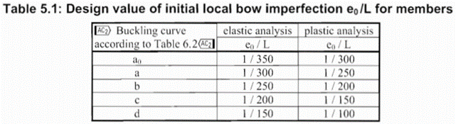
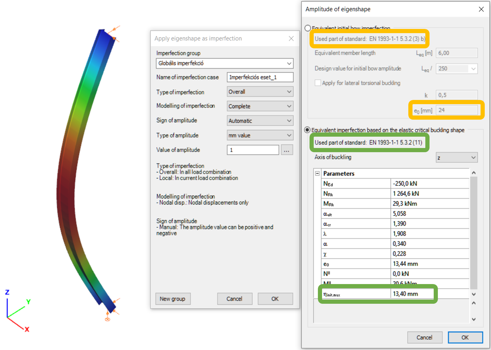
In the first part of this article, we reviewed the utilization difference and showed the relationship between the two methods. It was concluded that the method of chapters 6.3.1 (reduction factor) and 5.3.2 (11) (buckling mode based equivalent imperfection) are consistent at the load level equal to the buckling resistance of the member, so when the member utilization is 100%. The basic result of the procedure in 5.3.2 (11) is the amplitude (largest deflection value) of the equivalent geometrical imperfection. However, the Eurocode gives another simpler alternative for the calculation of this amplitude for compressed members in section 5.3.2(3) b) in Table 5.1, where the amplitude of an initial bow is defined as a portion of the member length for each buckling curves (Fig. 1.). We use the first column (“elastic analysis”) including smaller amplitude values.
It is an obvious expectation that these two standard procedures should yield at least similar results for the same problem. However, this is by far not the case in general.
In order to show the significance of the imperfection amplitudes this part is dealing with these two calculation methods, the variation of their values and the effect on the buckling utilization.
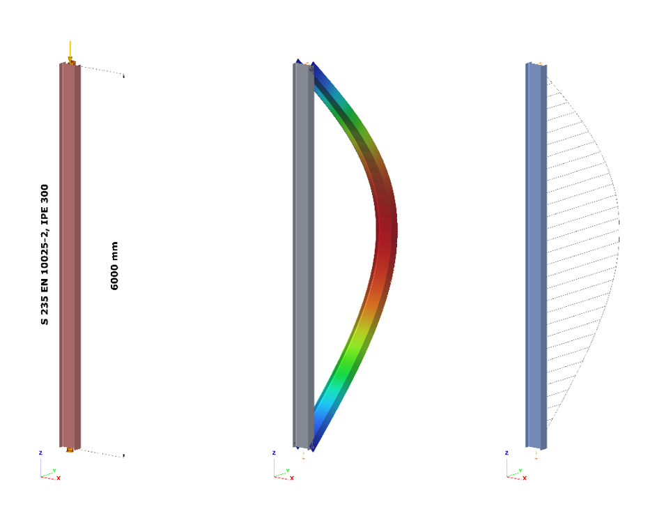
Let’s see again the simple example of Part 1: a simply supported, compressed column with a Class 2 cross-section (plastic resistance calculation allowed). The column is 6 meters high and has an IPE300 cross-section made of S235 steel. The two methods are implemented into Consteel and on Figure 2. it can be seen, that the two values for the amplitude of the geometrical imperfection is very different – e0 = 24 mm by the 5.3.2(3) b) Table 5.1 (L/250) and e0 = 13,4 mm by the 5.3.2 (11) (same as in Part 1).
Introduction
There are different ways to evaluate the stability of a structure. It is important to know the differences between those methods and the limits of applicability but it is also important to recognize the equalities in pure cases.
Methods of stability design
In Eurocode 1993-1-1, and so in Consteel, there are 3 methods to verify the stability of a model:
- Imperfection approach (described in Section 5.2 and 5.3)
The structural model is subjected to appropriate geometrical imperfections and after completing a second order analysis, only the cross section resistances need to be checked
- Isolated member approach ( described in section 6.3.1, 6.3.2 and 6.3.3)
The method is based on two essential simplifications:
- Structural member isolation: The relevant member is isolated from the global structural model by applying special boundary conditions (supports, restraints or loads) at the connection points which are taken into account in the calculation of the buckling resistance
- Buckling mode separation: The buckling of the member is calculated separately for the pure modes: flexural buckling for pure compression and lateral-torsional buckling for pure bending. The two effects are connected by applying special interaction factors.
- General method (described in section 6.3.4)
The basic idea behind the general method is that it no longer isolates members and separates the pure buckling modes, but considers the complex system of forces in the member and evaluates the appropriate compound buckling modes. The method offers the possibility to provide solutions where the isolated member approach is not entirely appropriate:
-The general method is applicable not only for single, isolated members, but also for sub frames or complete structural models where the governing buckling mode involves the complete frame.
-The general method can examine irregular structural members such as tapered members, haunched members, and built up members.
-The general method is applicable for any irregular load and support system where separation into the pure buckling modes is not possible.
Implementation of different approaches in Consteel
Isolated member approach is basically the reduction factor method and it can be performed in Member checks function in Consteel where it is possible to define the design parameters (e.g. effective length) by hand.
In Global checksfunction, cross-section and global buckling checks can be executed automatically according to the General method which does not require the direct introduction of effective lengths and other parameters depending on the distribution and combination of stresses along the member.
However, in pure cases (pure compression, or pure bending), buckling length calculated from general method can be equated with isolated member approach. In the following, a “how to” example will be shown on a pure compression column:
How can I get the buckling length of a certain member?
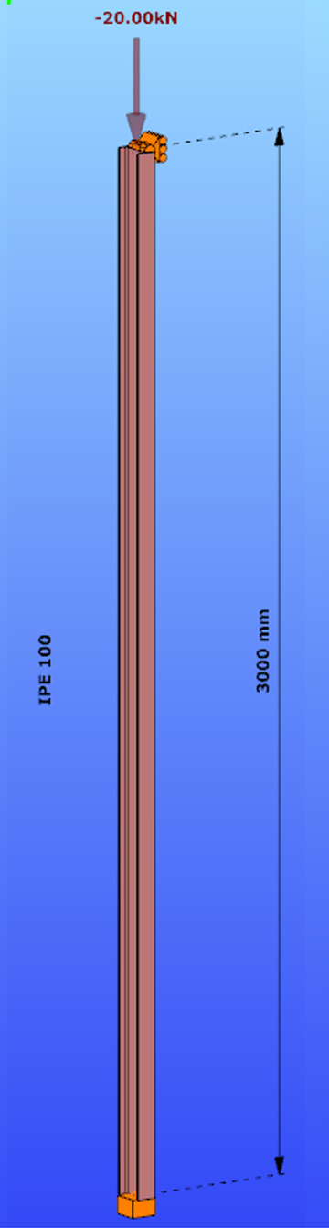
Parameters:
- Section: IPE100
- Material: S235
Main inertia around axes:
- Iy = 1708644 mm4
- Iz = 158056 mm4
Supports:
- x,y,zz on the top
- fixed on the bottom
Load: NED = 20 kN
Both the Isolated member approach and the General method require to calculate the slenderness value of the member. In case of the first method this is done through the use of buckling lengths. By using the General Method, the slenderness is calculated as the ratio of two amplifiying factors.
For the calculation of the equivalent buckling length we will need the first amplifier only, called critical elastic factor or alpha critical factor, obtained through a numerical analysis called linear buckling analysis.
Determination of alpha critical factor with buckling analysis:
Alpha critical factor: Minimum amplifier for the design loads to reach the elastic critical resistance of the structural component with regards to lateral buckling.
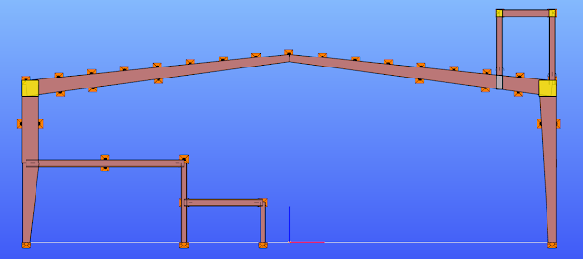
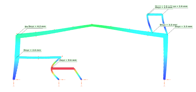
gateIn everyday practice frames of pre-engineered metal buildings are often designed as 2D structures. Industrial buildings often have partial mezzanine floors, attached to one of the main columns, to suit the technology. Additionally, such buildings often have above the roof platforms for machineries.
When it comes to seismic design, as long as seismicity is not deemed to be a strongly controlling factor for final design, the mezzanines are just attached to the same type of frames as used at other non-seismic locations and are locally strengthened, if necessary. Only the horizontal component of the seismic effect is considered in most of the cases.
The following picture shows a typical intermediate frame of a longer industrial hall, with built-in partial mezzanine floor and with a platform placed above the roof.
Equivalent Lateral Force method
The most straightforward design approach is the Equivalent Lateral Force (ELF) method (EN 1998-1 4.3.2.2). There are certain conditions for the application of this method.
- (1)P. this method may be applied to buildings whose response is not significantly affected by contributions from modes of vibration higher than the fundamental mode in each principal direction
- (2) the requirement in (1)P is deemed to be satisfied in buildings which fulfill both of the following conditions
o they have a fundamental period of vibration smaller than the followings
4*Tc or 2.0 sec
o they meet the criteria for regularity in elevation given in 4.2.3.3
When a dynamic analysis is performed on this 2D frame, the following vibration modes are obtained:

The first condition is met, but the criteria for the regularity in elevation is difficult to be judged. The first condition of 4.2.3.3(2) is met, but 4.2.3.3(3) is not really, as the mass is not decreasing gradually from foundation to the top, because of the heavily loaded above the roof platform.
Let us disregard for a moment this second criteria and accept the ELF method.
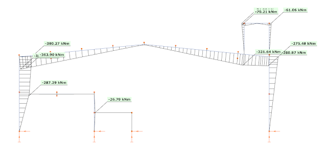
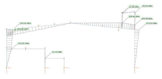
When the ELF method is applied, only the first (fundamental) mode is used, with the total seismic mass of the building carried by this frame. As the seismic effect is described with one single fundamental vibration mode only, the representation of the seismic effect is a simple equivalent load case, called as dominant load. Using this regular load case all the common first and second-order analysis can be performed, as also the linear buckling analysis. For example, the bending moment diagram calculated from the dominant mode (from left to right) is the following:
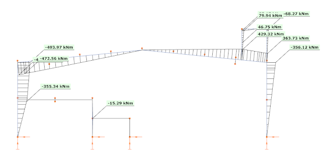
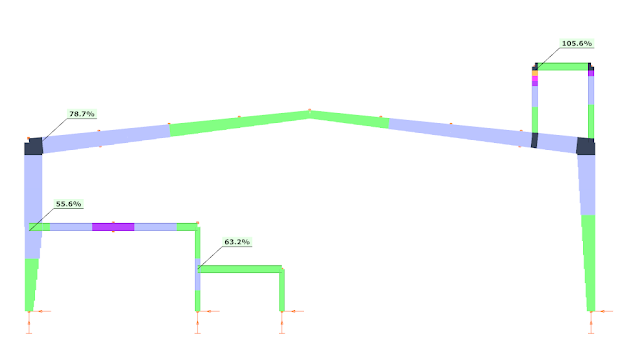
This way Consteel can perform an automatic strength and stability verification for the seismic combinations. The results are visible here, respectively:
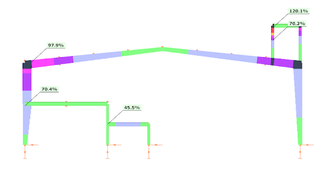
As it can be seen the structure is generally OK for strength, but there are some local overstresses at the platform and the utilization ratio is very high at the left corner. Regarding stability verifications the section seem to be weak. So – as expected – it is a key importance to be able to perform the stability verifications.
Of course, the platform column could be strengthened and close this exercise. But somebody can still have some doubts about the applicability of this ELF method, due to the criteria of vertical regularity.
Modal Response Spectrum Analysis
How could this structure be more precisely calculated? The general approach proposed by EN 1998 is the Modal Response Spectrum Analysis (MRSA) (EN 1998-1 4.3.3.3). This method is applicable in all cases, where the fundamental mode of vibration alone does not describe adequately the dynamic response of the structure. MRSA will take into account all the calculated vibration modes, not only the fundamental and therefore the precise seismic effect can be worked out on the structure. But the main problem is that this will result an envelope of the maximum values of internal forces and displacements, without any guarantee that these correspond to the same time frame of the seismic action. Plus, the internal forces produced at ends of members connected to a given node are not even in static equilibrium…. And even the sign of the internal forces or deformations is only positive due to the use of modal combinations SRSS or CQC. And even worse, as the seismic action calculated this way cannot be described by a single load case or by a linear combination of multiple load cases, no linear buckling analysis can be performed and therefore the automatic buckling feature of CosSteel cannot be used.
Let us see what MRSA with a CQC combination would give.
The first 7 vibration modes with the corresponding seismic mass participation values can be seen in the next table. The first column shows the frequencies in Hz and the second column shows the mass contribution factors in the horizontal direction. The other columns mean the mass participation in the other directions (out-of-plane and vertical), but these are not important for our example.
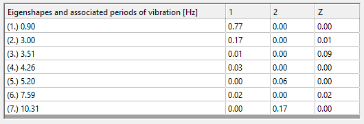
EN 1998 requires to consider enough vibration modes in each direction to reach a minimum of 90% of the seismic mass.
With Consteel the first 7 vibration modes have been calcualated and the results are shown in the table. Direction ‘1′ means horizontal in-plane direction while ‘2’ means horizontal out-of-plane direction and ‘z’ means the vertical direction. We are concentrating now on the vibrations which happen in the plane of this frame.
As visible, the fundamental mode has high contribution (77%) but does not reach the required level. The difference may justify the initial doubts about only using this single mode and disregard all the others. To fulfill the 90% minimum criteria, the second mode (17%) must be also considered, but visible even the 4th and the 6th have non-zero (although less then 5%) contributions in this direction.
As said before Consteel can perform only strength verifications but no stability verifications based on results obtained from an MRSA combined with CQC modal combination rule.
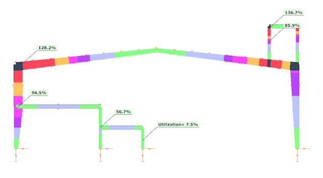
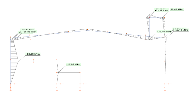
The bending moment diagram with the maximum possible values looks as shown below (all the bending moment values from the multimodal result are without a sign, they must be assumed as positive and negative values as well):
The results of the strength verification are the following:
As visible the platform leg is still weak, it must be strengthened without a question. On other hand the utilization ratio (without stability verification!!) at the left corner is lower, therefore there is a chance the the ELF-based 97.9% strength verification result could be still acceptable as safe, but the stability must be checked somehow.
But it is also visible, that generally the bending moments obtained by MRSA CQC are much lower than those obtained with the ELF method. Why is this? And how can a stability verification be performed?
Consteel approach
Seismic modal analysis with “selected modes”
Luckily Consteel provides a very flexible approach, called as „selected modes” method. This allows the user to pick the vibration modes and create linear combinations from them by specifying appropriate weighting factors. As a result, a linear combination of the modal loads calculated from vibration modes is obtained, instead of the quadratic SRSS or CQC combinations, which can be considered already as a single equivalent load case and all the necessary first- and second-order static and linear buckling analysis can be performed, as in the case of ELF calculation.
The definition of the „selected modes” and the specification of weighting factor is not an automated process in Consteel, it must be driven by the user. To be successful, it is important to understand how the structure works.
Although the first 2 vibration modes together already fulfill the minimum 90% mass contribution requirement, let us see the additionally also the 4th mode:
1st mode f=0.90 Hz, T=1.109 sec
2nd mode f=3.00 Hz, T=0.334 sec
4th mode f=4.265 Hz, T=0.234 sec
The colors suggest that the fundamental mode describes globally the structure, but the second seems to affect additionally the platform region and the 2nd or 4th is dominant for the mezzanine structure.
The corresponding bending moment diagrams are, respectively:
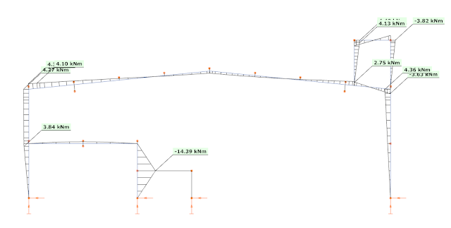
These bending moments also justify the assumption made based on the colors, the 2nd mode creates significant bending moments additionally to the first mode and the 4th mode creates significant bending moments additionally to the 1st mode. But it seems that also the 2nd mode created significant bending moments at this region.
It is interesting to note, that the bending moment diagram from the 1st mode (picture 9) almost perfectly fits to the CQC summarized bending moment (of course by assigning signs to the values based on the fundamental vibration mode) (see picture 4), except in the regions of the platform and the mezzanine. This means that in general the fundamental vibration modes describes quite well the dynamic response of this frame. And because of this, the bending moments could be calculated with the mass contribution factor corresponding to this mode (77%). And this is the reason, why the ELF method gives higher bending moment values, as there the same vibration mode was considered, but instead of the corresponding mass (77%), with 100% of the seismic mass.
As we discovered, the 2nd mode should be used together with the 1st mode to correctly describe the platform region, as this region is not fully dominated by the 1st mode only, the 2nd has a significant contribution.
Similarly to the mezzanine region, additionally to the 1st mode, here the 4th mode must be used to better approach the correct result.
gatePart 1: Buckling utilization differences
The Eurocode EN 1993-1-1 offers basically two methods for the buckling verification of members:
(1) based on buckling reduction factors (buckling curves) and
(2) based on equivalent geometrical imperfections.
This article reviews how these two methods relate to each other in terms of the final member utilization. For the sake of simplicity, we consider only members subjected to pure compression, undergoing flexural-buckling. For case (1) the chapter 6.3.1 is used while for case (2) the imperfections are considered to take the shape of a buckling mode and the corresponding chapter is the 5.3.2 (11).
It is an obvious expectation that these two standard procedures should yield the same utilization for the same problem. However, this is by far not the case in general.
Let’s see the following simple example of a simply supported, compressed column with a Class 2 cross-section (plastic resistance calculation allowed). The column is 6 meters high and has an IPE300 cross-section made of S235 steel. The standard amplitude for the buckling mode based imperfection is calculated by Eq. 5.9-5.11, that is equal to v0 = 13.4 mm. The next figure shows the model, the buckling mode shape – which is a classic flexural buckling about the weak axis – and the second order weak axis bending moment distribution.
- Important to note that the verification based on equivalent geometrical imperfection should be calculated from the results of a second order analysis using the linear cross section check defined by Eq. 6.2 (or Eq. 6.1 for elastic cases).
The most utilized cross-section will be the middle one, where the second order bending moment value depends naturally on the level of compressive force according to the well-known amplification relationship:
$$M_{zII}=N_{c,Ed}*v_0*\frac1{1-\frac{N_{cr}}{N_{c,Ed}}}$$
where is the applied compressive force, Nc,Ed is the amplitude of the equivalent geometrical imperfection and 1/(1-(Ncr/Nc,Ed)) is the amplification factor depending on the elastic critical load Ncr = 347,6 kN (Euler load). The utilization of this critical cross-section can be calculated according to Eq. (6.2):
$$U^{IMP}_{max}=\frac{N_{c,Ed}}{N_{Rd}} +\frac{M_{z,II}}{M_{z,Rd}} =N_{c,Ed} \Bigg[\frac{1}{N_{Rd}} +\frac{1}{M_{z,Rd}} *v_0*\frac1{1-\frac{N_{cr}}{N_{c,Ed}}}\Bigg]$$
Figure 2. shows the relationship between the applied compressive force and the second order bending moment and utilization of the middle cross-section where NRd = 1264,6 kN and Mz,Rd = 29,28 kNm. It can be clearly seen that the utilization is nonlinearly depends on the compressive force level due to the nonlinearity of the second order bending moment. The utilization corresponding to the 100% value gives the buckling resistance of the column:
GateThe main objective of the research paper is to present the technical and economical results obtained for standardized structures with small and medium spans. The obtained results can represent a starting point for designers as well as for investors, who intend to build single storey steel structures. According to the research, there have been identified a series of interrelated factors which may represent sources of savings in the optimization process. The authors highlight the work strategy in creating standardized structural systems that will improve product performances. The paper analyzes three standardized configurations including the following structural solutions: frame structures made of hot rolled beams and columns, thin-walled frame structures and structures using trusses and rectangular hollow sections columns. All configurations have been analyzed using Consteel 7.0 design software, for Bucharest region, loads evaluation being performed according to the current standards. Free height of the building varies between 4.00m and 6.00m, bay between
4.00m and 5.00m, and the span between 8.00m and 12.00m. The article presents the principle of the structural configurations and gives reference charts in order to estimate the steel consumption per square meter, aiming structural performance in what concerns price per square meter and execution time.
Click the button bellow to download and read the full article. (ROU)
gateThe authors will describe in the following pages the reasons why the project of the Multi-functional Sports Hall from Cluj Napoca is attractive. The main lines of the building are: a hall with a capacity of 7000 seats, a structure dominated by precast concrete elements, a long span roof and an advanced analysis of the connections, all well-kept into the limited funds. The roof solution consists in using steel space trusses made out of square hollow sections (SHS). The truss has a clear span of 63.90m, a total length of 76,10m, a maximum height of 4,00m that is reduced on the length of the structural
element, and a triangular cross section being 3,60m wide. Global stability checks and specific local stability problems were performed and are exposed in the following paper. For the fabrication of the space truss, welded joints between the SHS profiles were designed. As a result of the fact that for characteristic failure checks of the welded TT and KK joints analytical methods are based only on a semi-empirical formulae, developed for Φ=90 degrees (the angle between the diagonal planes), for the design of joints finite element modelling was used. Good agreement between the results of the developed finite element joint model and the analytical method for TT and KK joints has been found, even though the semi-empirical formulae are applied for the analysed truss which had Φ=50 degrees.
Click the button bellow to download and read the full article
gateThe construction of Kopitnari International Airport was one of the most important Georgian brownfield investments in 2011-2012. The 5000 m2 steel terminal building with timber interior, a spectacular member of the complex, had been designed by the Dutch architect office UNStudio; under the egis of MTM Ltd. the super-structural design had been executed by CEOS Ltd. The whole project had to follow a tight time schedule: the design process started in autumn 2011; the Airport opened its gates on the 15th September, 2012. The structural design was performed by using Hungarian FEM software for analyses and the integrated BIM system, TEKLA for 3D modelling. The fabrication of the 500 tons steel structure was done by Hungarian Rutin Ltd. Every element was road-transported to the 3000 km far Kutaisi. The terminal’s structure arrived in 4 parts according to the layout-quarters. The erection process had been done by Rutin Ltd. as well, 10 workers spent 5 weeks in Georgia while finishing the complete structure. Design, BIM, fabrication and site work together led to the final result: The supporting structure was erected in time, no site corrections were needed. After finishing a Georgian member of the team made the statement: “Hungarian engineering and construction in Georgia guarantee the success!”
Click the button bellow to download and read the article.
gateHaving as a starting point the idea of creating a structure with an iconic design, the current article presents all the technical solutions and steps followed in the process of creating this special structure. The structure, having the destination of a showroom for an auto dealer, is presented with an unconventional design of the roof: a roof structure having a double curvature. Starting from a relatively simple structural system, the evolution steps are presented together with the main setbacks, challenges, and the final solution: a completely redesigned structural system, with high-performance elements, both in strength and material consumption. The article also presents some stages of the structural analysis, with provisional results that shaped and determined the final design of some of the structural elements.
Click the button bellow to download and read the full article.
gateNowe trendy w normach: EUROKOD 3 – efektywne globalne projektowanie konstrukcji.
Kliknij przycisk poniżej, aby pobrać i przeczytać cały artykuł.
gateThe case study exposes a practical evaluation of fire resistance of an old structure of a Spanish industrial building composed of steel built-up members; the truss members are angles connected through packing plates and the columns are battened chords. A simple calculation model was used element by element. First, heat is transferred to individual steel elements by convection and radiation in thermal study. The contributions of these two modes of heat transfer were treated by a practical approach. In mechanical study, the second order analysis was used with global imperfections. Finally, the fire resistance was evaluated R15 after some proposals.
Click the button bellow to download and read the full article.
gate