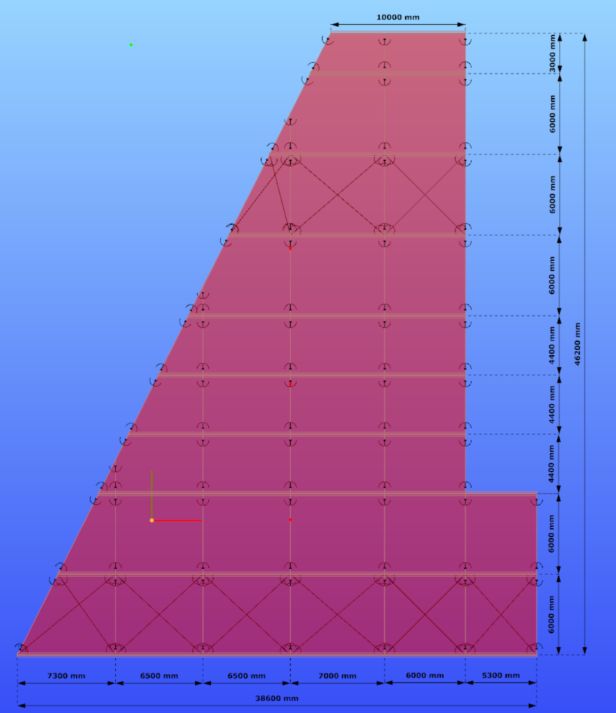
Example hall model for trying the smart link feautre in Consteel

Watch our user guide about How to use the smart link feature to learn more.
gateExample model for trying the smart link feature in Consteel
Watch our user guide about How to use the smart link feature to learn more.
gateSmart link feature in Consteel
The smart link is a different version of the already existing link element, that was introduced into Consteel with version 14. In case of the smart link, we developed a different definition method for easier application. The smart link is also capable of updating its geometry based on changes made to other elements that it connects. This way it provides a more versatile modelling tool.
Check out the video for more info and practical examples!
gateGeometry definition
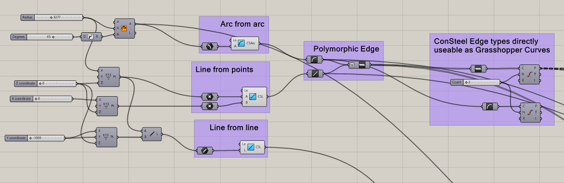
Geometry in Pangolin can be described by lines or circular arcs and polygons made up of the former two. The relevant components are the simplest ones, acting as converters from the native Grasshopper geometry types, with the possibility of specifying a Consteel Layer.
Section definition
The geometry definition of the sections is more refined since Consteel uses detailed section models composed of solid representation for analysis and thin-walled representation for standard design checks. There are two options to create sections in Pangolin: use a predefined section from the section bank or create custom sections by predefined parametric macros.
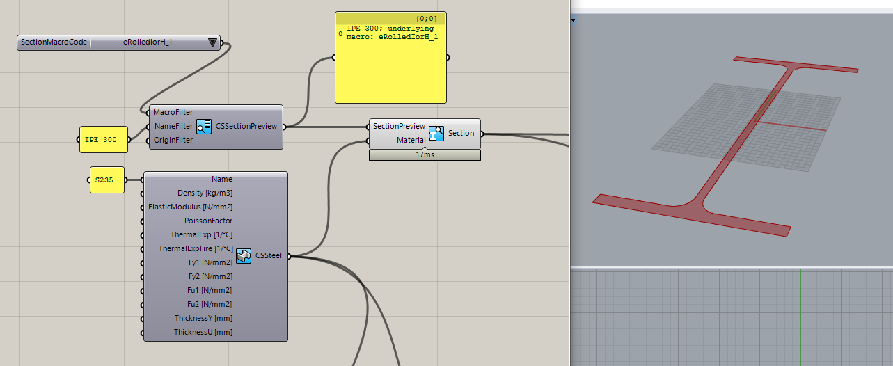
Predefined sections from section bank
7000+ different profiles can be defined from the section bank (hot-rolled, cold-fromedetc.). This workflow contains two steps: 1. Getting the section preview from the bank. 2. Getting the actual section from the preview. (The reason for this is the performance, as in Pangolin sections are real objects, loading all the 7000+ sections from our bank would take minutes even on a powerful pc.) The section bank component provides various filtering options, to help select the section. After the desired section preview is selected, you can create a real section from it along with a material, and check the cross-section surface in Rhino.
Custom sections based on predefined macros
This workflow consists of placing a section macro component, selecting a base macro, and defining the macro parameters.
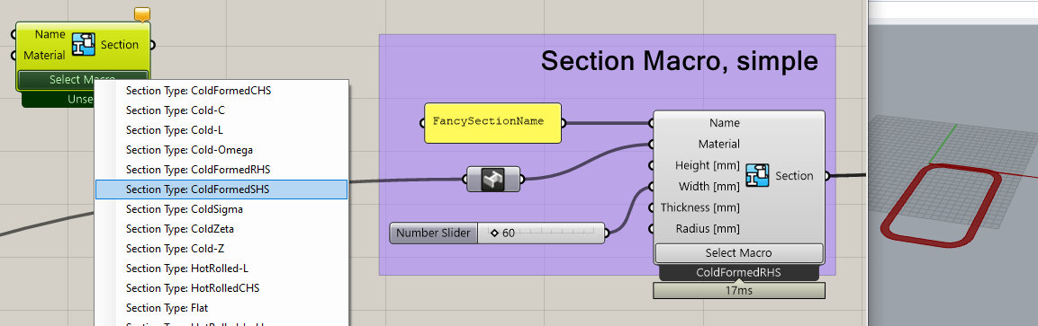
One of the most important unique features of Consteel is its advanced analysis and design calculations for members with cold-formed sections having various stiffeners. Correspondingly Pangolin makes it possible to create custom cold-formed sections, with custom stiffeners parametrically:
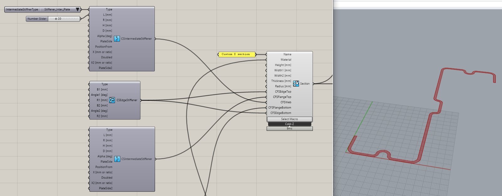
As you can see, the components help in building complex sections with available default values providing a wide range of parameters to be customized.
Structural member definition
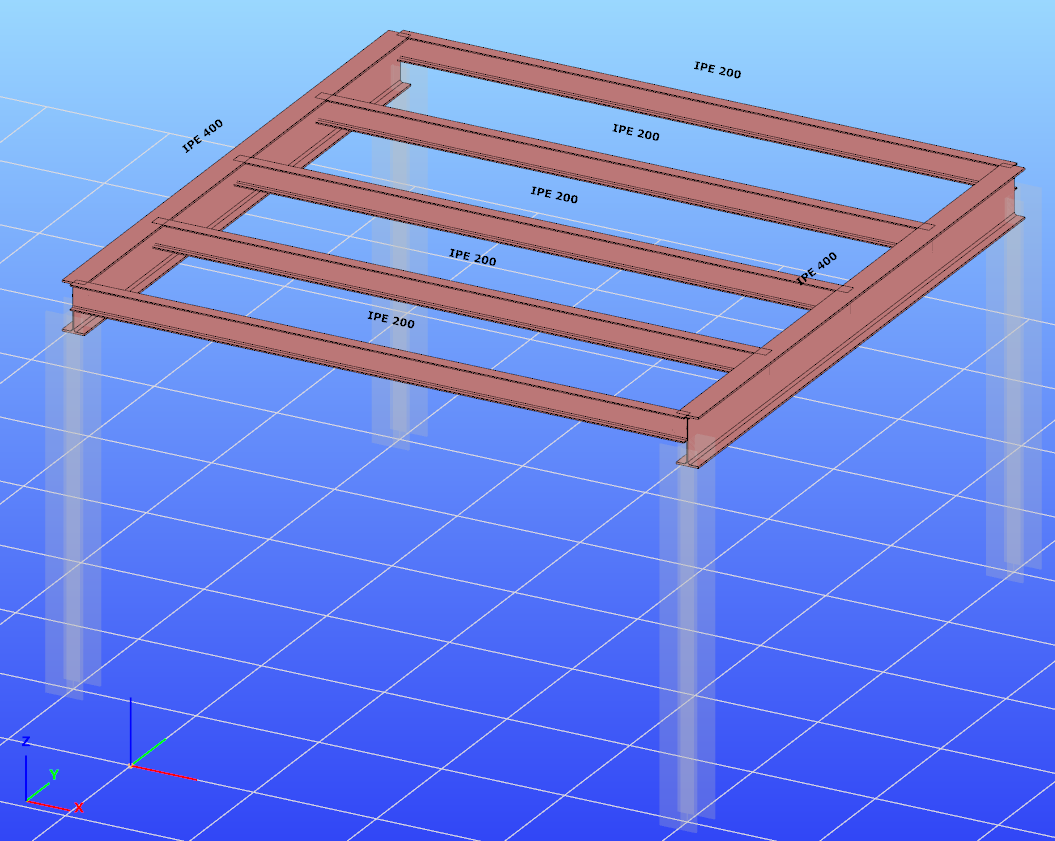
Defining beams is as easy as pulling the reference edges and the beam section into the Beam component:
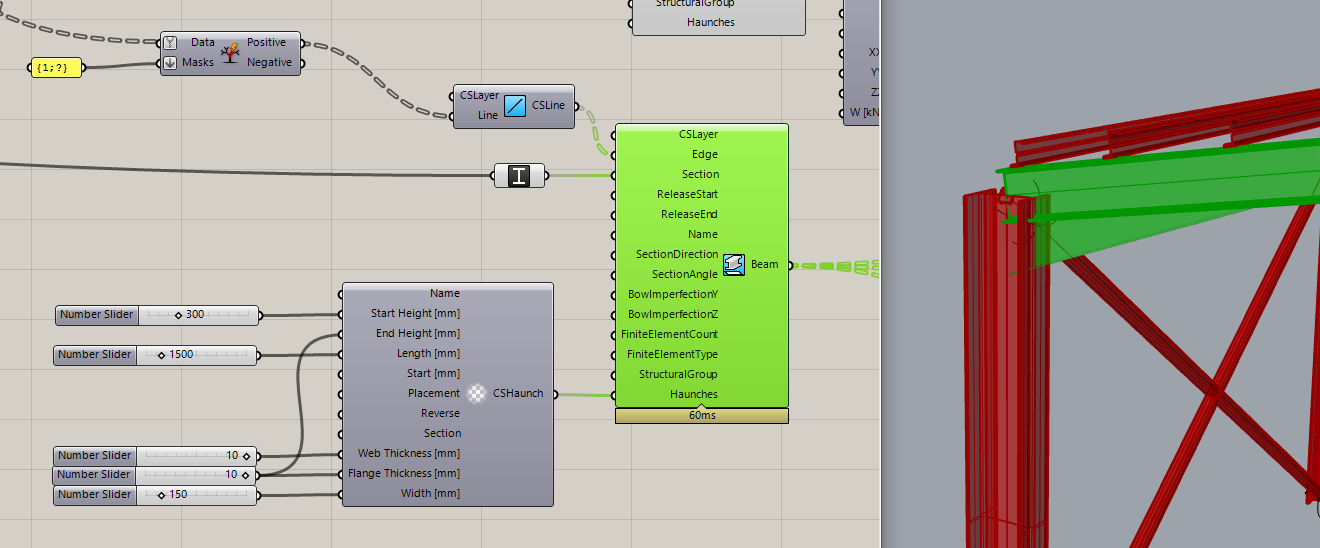
In the example above we also defined a haunch on the beam ends, another unique feature of Consteel, which will be taken accurately into account during analysis and design.
To make modelling easier, Pangolin also provides several useful implicit data conversions, like in the picture above: at the start, we have the IPE 300 beams, and just connecting them into a Grasshopper Plane parameter, the beams get converted to their local coordinate systems. This plane can be directly connected with the Z purlins section direction parameter to correctly lay them upon the main beams.
Structural details
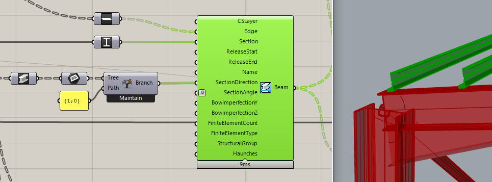
Let us stop at the purlins for a moment! Pangolin also provides a detailed linking of structural objects through Consteel’s link elements which can be rather important in order to consider accurately the lateral restraint effect on the beam provided by the purlins.

The definition of link elements includes setting the interface position, the direction, and the stiffness attributes of the connection. Defining supports for the model is also helped by automatic conversions, where you can directly ask a beam’s endpoint, and place the support there, instead of manipulating with indexes through a complex definition.
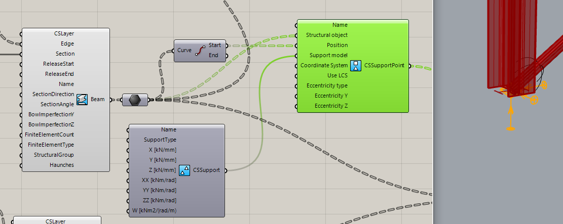
Pangolin also provides the possibility to define edge and plate supports.
Load definition
gateConsteel is a powerful analysis and design software for structural engineers. Watch our video how to get started with Consteel.
Contents
- Define load groups and load cases
- Generate load combinations
- Define line loads globally
- Define partial line loads locally
Consteel is a powerful analysis and design software for structural engineers. Watch our video how to get started with Consteel.
Contents
- Load sections
- Creating beams and columns
- Place supports
- Haunch definition
- Frame corner definition
Read our tips and tricks about Surface wind load on custom shape roof for more information.
Version: CS14.1000
gate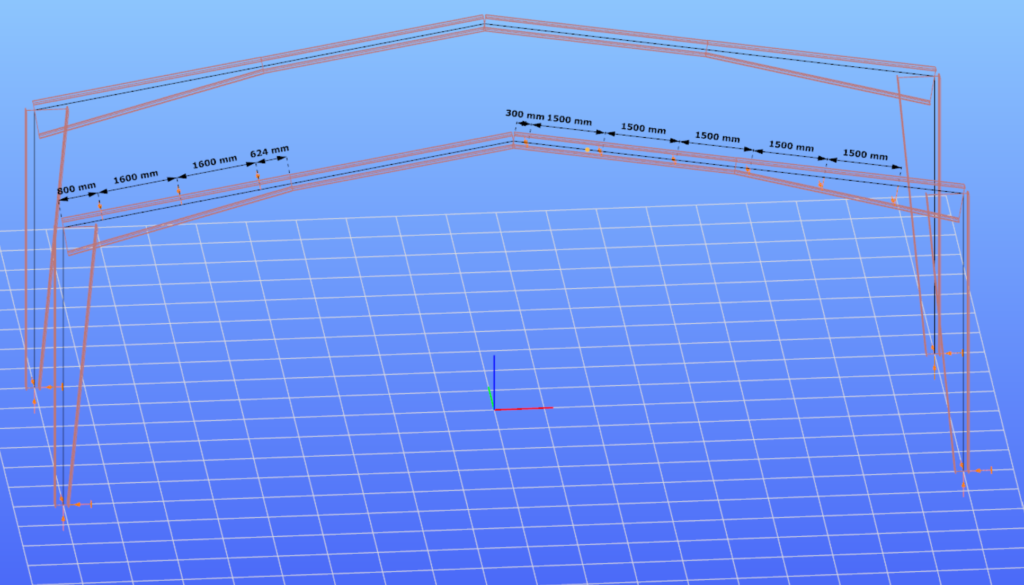
Read our tips and tricks about Placing of multiple point supports for more information.
Version: CS14.1000
Click the button below to download the example model.
gateIntroduction
In Consteel there is a possibility to perform a model check on the structure to reveal modelling errors. This model check or diagnostics can be separated to First and Second level model diagnostics.
How it works
The First level diagnostics runs automatically before starting the analysis. It contains two types of checks. First a quick check is running which verfies the minimum conditions of creating the finite element mesh. The second one is a geometrical check performed on the generated finite element mesh verifing for example if the loads and supports are actually on the structure or if there are overlaps between bar or surface elements.
The Second level diagnostics can be initiated manually at any time during the modelling stage to examine the current state. The function can be launched by clicking onView/Diagnostics…button. It starts also with the same quick check as the first level. Then a basic check is running examining e.g. too small distances between members or unproperly supported model parts.
It is recommended to perform second level diagnostics after the modelling of the structure to reveal errors coming from inaccuracies of the modelling. After these errors had been fixed, it is OK to proceed to the analysis, which will automatically trigger the first level diagnostics. If it still reveals model errors, it is easier to handle them if all of the problems from second level diagnostics had been fixed.
Diagnostic messages
There are two kinds of diagnostic messages:
ERRORS: They make the calculations impossible or meaningless to execute so the detected errors stop further calculations.
POSSIBLE ERRORS: The warnings allow the calculation to run but they can influence the results.
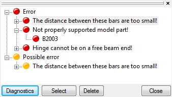
By clicking on any of the object name in the tree structure and pressing the SELECT button, the selected object will be highlighted in the model graphical surface. The selected object can be erased by pressing DELETE button, or it can be modified with the regular geometric operations.
Tutorial video
To see the use of the diagnostic tool, please watch one of our earlier tutorial video below:
gateIntroduction
In the last years, freeform architecture became more and more popular. A variety of complex geometric shapes are used for the facades of buildings, which brought the demand of new, innovative tools and solutions for modelling of these structures too. In Consteel we have developed such functions to make the engineers’ work easier.
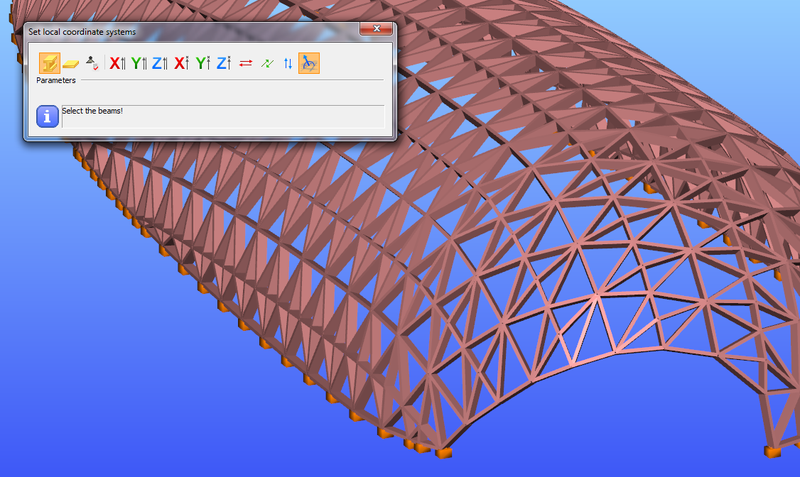
Section orientation
Orientation of the sections is always a problem. We have implemented a tool, with which the rotation of the sections can be done automatically. Sections can be rotated perpendicularly to the surface of the freeform shape of the structure. Z axis will be perpendicular to the surface formed by the connecting beams.
Load transfer surfaces
Covering a freeform structure with load transfer surfaces -like in the picture below-manually, would take a lot of time and effort. Our tool for multiple load transfer surface placement gives you a quick, easy and effective solution for covering your freeforms.
gate