- Zawartość
- Part 1: Buckling utilization differences
Buckling resistance of members: imperfection or reduction factor? - 1.
Part 1: Buckling utilization differences
The Eurocode EN 1993-1-1 offers basically two methods for the buckling verification of members:
(1) based on buckling reduction factors (buckling curves) and
(2) based on equivalent geometrical imperfections.
This article reviews how these two methods relate to each other in terms of the final member utilization. For the sake of simplicity, we consider only members subjected to pure compression, undergoing flexural-buckling. For case (1) the chapter 6.3.1 is used while for case (2) the imperfections are considered to take the shape of a buckling mode and the corresponding chapter is the 5.3.2 (11).
It is an obvious expectation that these two standard procedures should yield the same utilization for the same problem. However, this is by far not the case in general.
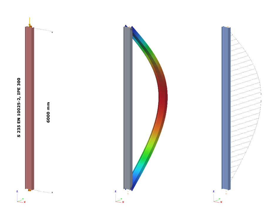
Let’s see the following simple example of a simply supported, compressed column with a Class 2 cross-section (plastic resistance calculation allowed). The column is 6 meters high and has an IPE300 cross-section made of S235 steel. The standard amplitude for the buckling mode based imperfection is calculated by Eq. 5.9-5.11, that is equal to v0 = 13.4 mm. The next figure shows the model, the buckling mode shape – which is a classic flexural buckling about the weak axis – and the second order weak axis bending moment distribution.
- Important to note that the verification based on equivalent geometrical imperfection should be calculated from the results of a second order analysis using the linear cross section check defined by Eq. 6.2 (or Eq. 6.1 for elastic cases).
The most utilized cross-section will be the middle one, where the second order bending moment value depends naturally on the level of compressive force according to the well-known amplification relationship:
$$M_{zII}=N_{c,Ed}*v_0*\frac1{1-\frac{N_{cr}}{N_{c,Ed}}}$$
where is the applied compressive force, Nc,Ed is the amplitude of the equivalent geometrical imperfection and 1/(1-(Ncr/Nc,Ed)) is the amplification factor depending on the elastic critical load Ncr = 347,6 kN (Euler load). The utilization of this critical cross-section can be calculated according to Eq. (6.2):
$$U^{IMP}_{max}=\frac{N_{c,Ed}}{N_{Rd}} +\frac{M_{z,II}}{M_{z,Rd}} =N_{c,Ed} \Bigg[\frac{1}{N_{Rd}} +\frac{1}{M_{z,Rd}} *v_0*\frac1{1-\frac{N_{cr}}{N_{c,Ed}}}\Bigg]$$
Figure 2. shows the relationship between the applied compressive force and the second order bending moment and utilization of the middle cross-section where NRd = 1264,6 kN and Mz,Rd = 29,28 kNm. It can be clearly seen that the utilization is nonlinearly depends on the compressive force level due to the nonlinearity of the second order bending moment. The utilization corresponding to the 100% value gives the buckling resistance of the column:

Log in to view this content
Online service access and support options are based on subscription plans. Log in to view this content or contact our sales department to upgrade your subscription. If you haven’t tried Consteel yet, try for free and get Pro access to our learning materials for 30 days!