Did you know that you can use Consteel to design simple supported, continuous and over-lapped purlins systems in Consteel, considering shear and rotational stiffness of attached roof sheeting?
To use the purlin design functions, you first need to place cold formed Z or C purlins in your model, these are the only profile types supported for purlin design. All functions related to purlin lines can be found in the Structural members tab.

With these three main functions you can define the purlin line object, specify the support zones, and set the overlap zones. A detailed explanation of each can be found in the Consteel Manual – Purlins Chapter.
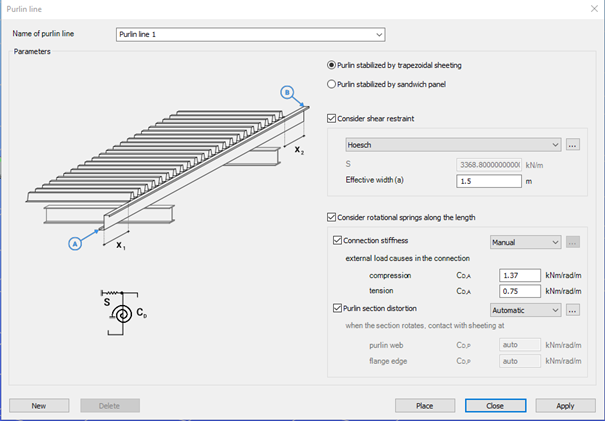
The Place purlin line function allows you to create and configure a purlin line object and place it precisely within your structural model.
You can also control the sheeting eccentricity in the Z direction, either by selecting predefined positions or by entering custom values. A graphical interface supports these settings to ensure intuitive and accurate placement.
An important feature of this function is the ability to simulate the supporting effect of roof sheeting on the purlins. This is done by applying spring stiffnesses that reflect how the sheeting contributes to the overall structural behavior. Two types of springs are considered:
- Translational (shear) spring, representing the shear stiffness of the roof covering.
- Rotational spring, accounting for both the connection stiffness and profile distortion.
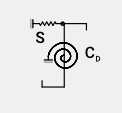
Depending on the selected sheeting type (trapezoidal sheeting or sandwich panels) the stiffness values can be entered manually or calculated automatically. Automatic calculations follow the guidelines of EN 1993-1-3, providing reliable and standards-based results.
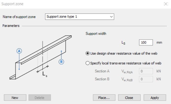
The Support zone function allows you to define the geometrical and mechanical parameters at the points where the purlins are supported. The geometry and bearing capacity can be set by specifying the support width and selecting how the load capacity is defined.
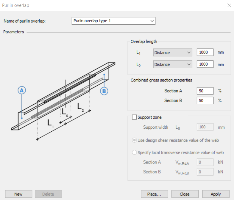
The Purlin overlap function helps define how individual purlins are connected in continuity. The standard (EN 1993-1-3) distinguishes between simple overlap joints and joints with coupling elements. Currently, only overlap joint is available in the program. You can define the length of the overlap either in millimeters or as a percentage of the member length. Additionally, the stiffness distribution between the two overlapping members can be adjusted.
Together, these functions ensure accurate modeling of purlin behavior, support conditions, and connection details, aligning with design standards and practical requirements.
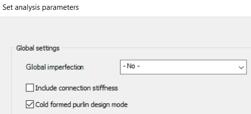
To ensure that all purlin line related objects are properly considered in the analysis, make sure to activate the Cold formed purlin design mode in the analysis settings. When this mode is enabled, both the buckling analysis and the global design are performed on a submodel that includes only those members associated with purlin line objects. This mode is intended exclusively for the design of the roof purlin system.
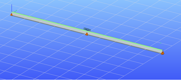
If purlin related objects are present in the model but the cold formed purlin design mode is not active, the structural elements connected to these objects will be excluded from the second-order stiffness matrix. As a result, their influence will not be considered during linear buckling or second-order analysis.
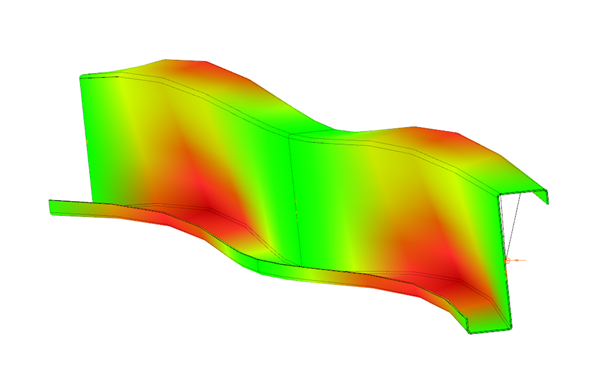
Download the example model and try it!
Download modelIf you haven’t tried Consteel yet, request a trial for free!
Try Consteel for freeDid you know that you could use Consteel to perform local and distortional buckling checks for cold-formed members?
First, sections must be loaded into the model. To load cold-formed sections, you can choose from four options: From library, Macro section, Draw section, or My library.

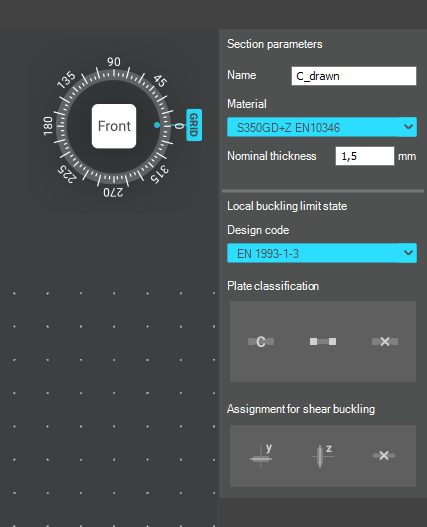
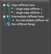
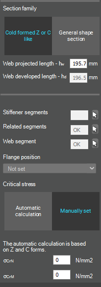
After the first-order and buckling analyses are completed, you can proceed to the Ultimate limit state check settings and enable the steel design cross-section and buckling checks. At the bottom of the steel design section, there is an option to Consider the supplementary rules from EN 1993-1-3 for the design of cold-formed sections. This checkbox must be selected if you want to design cold-formed sections.
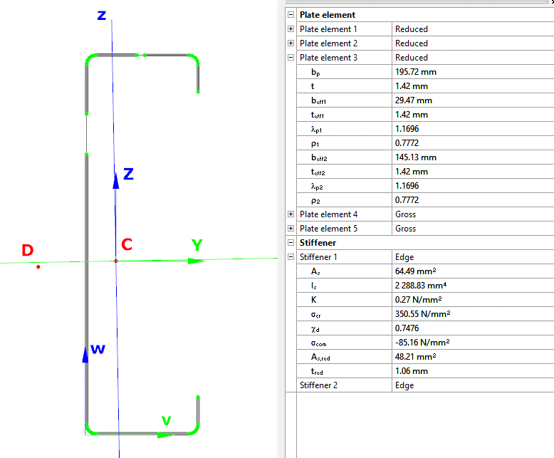
When the calculation is finished, by opening the Section module, we can review all the properties of the Effective section of the elastic plate segment model. By opening each plate element, we can verify the length, effective length, thickness, effective thickness, slenderness, and reduction factor separately. In addition, the properties of the stiffeners can also be verified: area, moment of inertia, lateral spring stiffness, critical stress, reduction factor, compressive stress, reduced effective area, and reduced thickness.
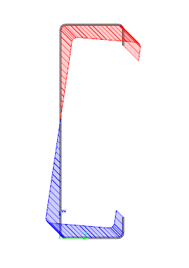
Similarly, the stresses can also be checked from the Properties tab. In the colored figure or diagram view, all the calculated stresses can be seen together with their resultants.
Consteel automatically takes into account the effect of distortional buckling when calculating the effective sections of cold-formed thin-walled sections.
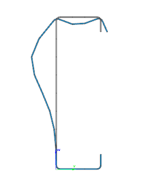
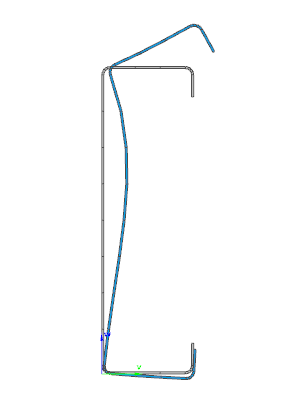
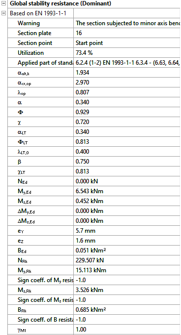
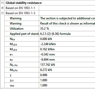
Moving on to the Standard resistance tab in the Section module, all calculated results can be verified, not only the dominant one. By opening the Global stability resistance check, we can see that, since we enabled the option to consider the supplementary rules from EN 1993-1-3 for the design of cold-formed sections, results are available both according to EN 1993-1-1 and according to EN 1993-1-3.
Download the example model and try it!
Download modelIf you haven’t tried Consteel yet, request a trial for free!
Try Consteel for freeDid you know that you could use Consteel to include in your model a wide range of cold-formed macro sections?
For line member modelling, the cross-section must first be loaded into the model. In Consteel, there are four options to do this, either starting from the Section Administrator or directly during beam or column modelling: From Library, Macro Section, Draw Section, or My Library.
Cold-formed sections can be created using any of these four methods. Standard cold-formed cross-sections can simply be selected from the library. However, if a special cold-formed section is needed, it can be created via Macro Sections, including: RHS, CHS, L profile, Z shape, C shape, Sigma section, Zeta section, Hat section with stiffeners, double C section, double Sigma section, and double user-defined sections.
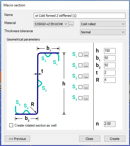
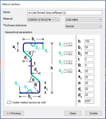
Macro sections are easy to create because the essential geometric characteristics are predefined, and the parameters can be modified intuitively. It is also possible to add profile stiffeners. Flange and web stiffeners can be configured in various forms, including single and double options. These defined stiffeners are included in the structural evaluation of distortional buckling, according to EN 1993-1-3.
The thickness tolerance category must be specified. This determines the design wall thickness for the section. In practice, macros follow the commonly applied tolerance categories used for coated steel sheet products.
If you want to use a double section, make sure to load into the model first the section that you want to duplicate.

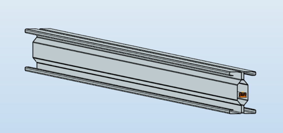
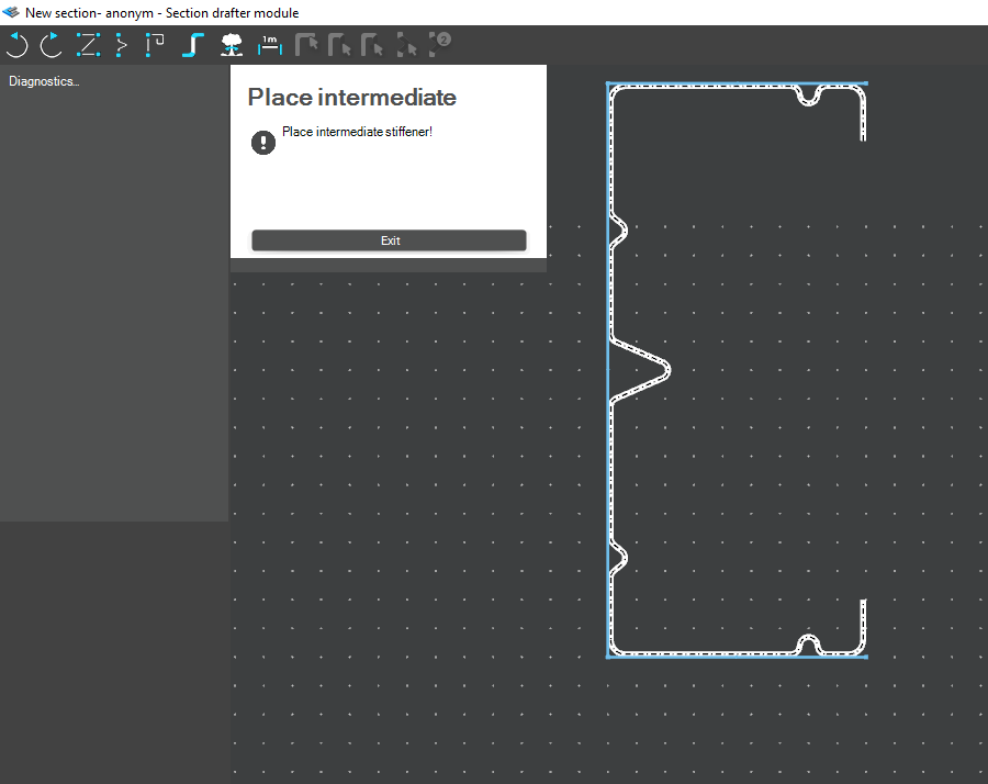
For very special or unique sections, the Draw Section function can be used. This allows users to create fully custom cross-sections when standard or macro shapes are insufficient, by manually sketching the geometry.
Sections can be defined as cold-formed or general thin-walled, which determines how they are analyzed: cold-formed sections have uniform thickness and account for distortional buckling, while general thin-walled sections allow varied thicknesses and closed shapes, typically for welded or fabricated profiles.
This approach is especially useful for modelling unique shapes, prototypes, or as-built sections, giving full control over every segment to accurately capture geometries that standard libraries or macros cannot reproduce.
Download the example model and try it!
Download modelIf you haven’t tried Consteel yet, request a trial for free!
Try Consteel for freeDid you know that you could use Consteel to design simple supported, continuous and over-lapped purlins systems, considering shear and rotational stiffness of attached roof sheeting?
Download the example model and try it!
Download modelIf you haven’t tried Consteel yet, request a trial for free!
Try Consteel for free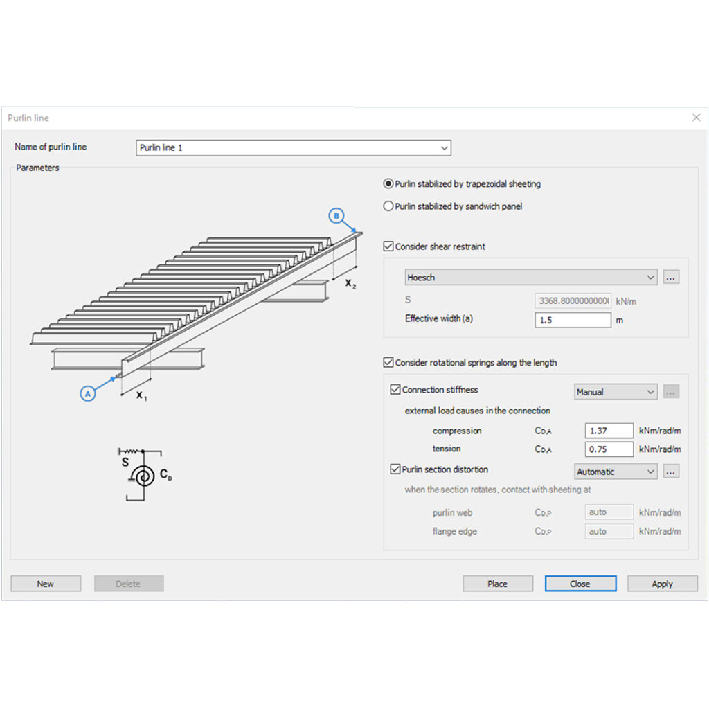
The results of analyzes of frames with a span of 12, 15 and 18 m have been presented. Their minimum mass was assumed as the optimization criterion. The finite element method was used in the calculations. The results of calculations in the form of: structure mass, bar resistance coefficient and checking the SLS condition were presented in the tables.
Click the button bellow to download and read the magazine brochure. (PL)
gateIn our series we have shown in Part 1 and Part 2 how the spring stiffness „K” is determined for and edge and for an intermediate stiffener. In this part we will show how to proceed further.
The goal is to determine how efficiently can this stiffener support the connected compressed plate. To consider local buckling of the compressed plate the effective widths will be calculated. These widths can be either calculated for a plate supported at both ends or for a plate supported at one end only, using Table 4.1 and Table 4.2, respectively.
If a stiffener fulfills the minimum constructive requirements, we will first assume that it is rigid enough the act as a support. Based on this we work out the effective lengths for the connected compressed plates, assuming also that they are fully loaded up to the yield strength. Once we know the effective widths of the plate parts connected to the stiffener, we also know the load this stiffener is supposed to be able to carry without buckling, to justify the first assumption. Therefore, next we calculate the flexural buckling resistance of the stiffener. If we find out that it is lower than what was implicitly assumed previously, we go back to the first step, lower the stress to be compatible with the obtained buckling resistance of the stiffener (distortional buckling). This lower stress level may of course result different effective widths. An iterative procedure is started until the satisfactory result is found. After completion the final stiffener buckling resistance value will be incorporated into an equivalent effective thickness applicable for the stiffener and the connected effective plate parts.
In the above described iterative process the „K” value of the stiffener will be needed to determine the flexural buckling resistance of the stiffener. This resistance will be calculated using the help of a simple beam model, where the stabilization provided the remaining parts of the section is used as a continuous bedding of „K”. The cross section of the beam corresponds to the stiffener and connected plate parts and will be exposed to the actual stress level of the iteration, assumed as a simplification to be constant along the length. The length of the beam in this model is unknown at the moment, it should be equal to the half wavelength of the buckling shape which is expected to be around 1.5-3 times the height of the studied cold-formed section.

Distortional buckling will appear only if the length of the stiffener is much longer than this typical length range. As a further simplification Eurocode assumes infinite length as the possible worst case, because for this condition an analytic solution exists in the literature:
In this formula „K” is the spring value – shown in Part 1 and Part 2 – represents the spring stiffness value what the remaining section can provide to the stiffener. Isand Asare section properties of the corresponding stiffener together with connected effective widths of supported plates, namely area and inertia around an axis perpendicular to the expected direction of buckling of the stiffener. E is the Young modulus of the steel material.
The formula gives the critical stress level where elastic buckling would appear. Once this has been found, reduced slenderness is calculated, and the distortional buckling resistance can be obtained by using a special buckling curve given by (5.12a-c) formulas of EN 1993-1-3.
The validity of formula (5.15) can be easily demonstrated with a simple Consteel model.
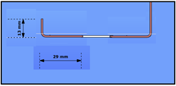
Let’s assume the Z section from our 1st blog exposed to compression force and let’s assume that we have already calculated effective width values. Yield strength of the material is 235 MPa and coating thickness is 0.04 mm. We found that the effective width of the lip and flange are ceff=13 mm and beff=29 mm, respectively.
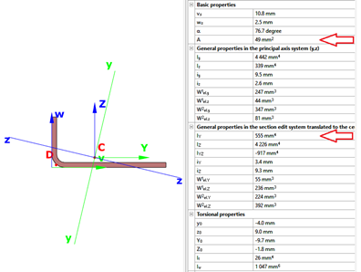
The section properties can be calculated with Consteel
gateDistortional buckling – Further secret formulas of EN 1993-1-3. Check our article for the first secret formula if you hadn’t read it yet.
In our series we continue with the second „secret” formula of EN 1993-1-3.
This formula (5.11) is used when the ability of an intermediate stiffener to stabilize a compressed web plate is studied.
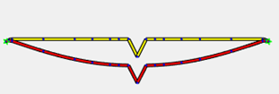
When the intermediate stiffener is rigid enough, it divides efficiently the longer web plate into shorter plates. During buckling a rigid stiffener will not displace and the plate will buckle between the ends (stabilized by flanges) and this stiffener:
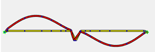
If the stiffener is not rigid enough, already at a much lower stress level the distortional buckling will appear which is characterized by a displacement of the stiffener and by the web plate buckling with a half-wave equal to the plate length:
In such a case Eurocode still accepts that web plate buckling will occur between ends and intermediate stiffener, but reduces the thickness of the intermediate stiffener zone, to compensate for the less than ideal rigidity. This compensation will depend on the buckling resistance of the stiffener when subject to compression.
The simplified model used by Eurocode in the procedure can be seen below. As a simplification it is assumed that the web plate is connected to the rest of the section with hinges. It means that it’s buckling shape is not influenced by the stiffness of connected parts, they do not encaster its ends, its ends can freely rotate. The ends of the plate are supported and there the plate can provide an elastic bedding to the stiffener, which will be considered as a „help” when its buckling resistance will be determined. This bedding is represented by the K spring stiffness:
The spring value which represents in this model the bedding provided by the plate is calculated as the ratio of the displacement obtained from the application of a unit load at the center of gravity of the stiffneer. In this case the unit load is applied perpendicularly to the web plate. Formula (5.11) gives the deflection (δ) from such unit load (u).
gate

